Networking and Communications
This has been a very long week. We had to design, build, and connect wired or wireless node(s) with network or bus addresses.
This is actually a great opportunity to develop my final project. More details in the Project page, but in short:
For now, I want my game to have four moles (or beavers). Therfore, I need to build: 4 station boards (a.k.a. beaver boards), one master board (a.k.a. master beaver), incorporate bluetooth to the system.
Beaver boards
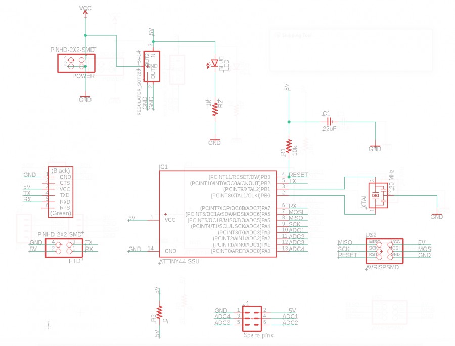
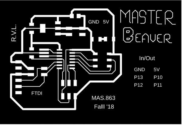
I started by modifying the beaver board that I designed a couple of weeks ago. I changed the 6-pin FTDI connector for a 2x2 header (this way, I can easily connect the boards among them using ribbon wire and the 2x2 header caps). I also changed the sonar- and the servo connections to something more sturdy, and added a port for the unused pin of the ATtiny44. I dont't know if I will use it or not, but just in case ... (a second servo/sonar perhaps?). These were very minor modifications, but what it really took tim was to mill/stuff four new boards... Here the schematic and the traces for the final version:
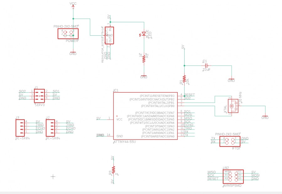
Beaver board schematic
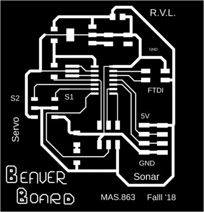
Beaver board traces
Master board
The master board will be the link between the beaver boards and my computer (initially serial-wired, hopefully bluetooth in the future). Also, under the autonomous game version, it will collect sonar data from beaver boards, assess the most suitable location for the beaver to appear, and send the command to the chosen board. The master board has both the classic 6-pin and the 2x2 FTDI connectors.
Since there were four unused pins of the ATtiny44, I added an expansion header in case I may need those... For know I milled a mini-LED board that connects to it, and that I can use during troubleshooting.
Mini-LEDs board (for troubleshooting) with a 2x3 pin header
Here the schematic and traces of the master board:
Master board schematic
Master board traces
Power everything up!
Each board has a 5V-1A power regulator. My original idea is to get an external power supply, and connect all of the boards to it. To get an idea of how much I need I measured the power consuption, which was about 0.5A (@ 5V) for 1 motor. Being coservative I could expect up to 2A because not all the motors were going to move at the same time... These power requirements are too high if I want to use a small batery, but quite standard if I use a high-amperage USB charger (which I happend to have). For this I made a simple connection using the USB traces in the Fab library of Eagle.
Power connection to high-amperage (3.4A) USB charger
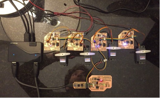
Use master to communicate with beavers (similar to Neil's asynchronous example)
For the actual network I used a serial bus connection. That means that the RX pins of each beaver board will be connected to each other, and to the TX pin of the master beaver. Similarly, the TX pins of the beaver boards will be connected to the RX pin of the master board.
The code (that can be found at the bottom) is quite simple: in order to send a command/request, the master board will send a specific ID address to all the boards, but only the relevant one will wake up. After receiving the call, the slave board will send an "acknowledgement message" back. And only then, the master will send the command/request. Finally, after receiving the command/request (and executting it), the slave board will send a final "acknowledgement message" and then become passive (i.e. it will only listen). Now, a key in serial communication is to tell the beaver (slave) boards when to talk, BUT also when not to. This can be implemented in arduino just by setting the TX pins to INPUT or OUPUT. See details in the INO code below. Also note only the only necessary programming is within the slave boards. In this example the PC (i.e. me) is acting as the master
Here I leave a video explaining the networks and demostarting how it works>
Autonomous game: Master makes the decision
In this case, I will embedded a small program into the maaster beaver board. It will basically reproduce what I did with the console (i.e. waking up the beavers and ask them to move up). The game flow is explained in the figures below:
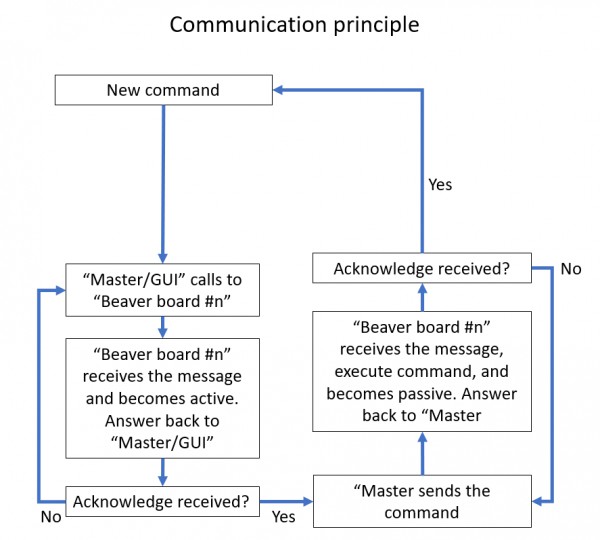
Communication principle
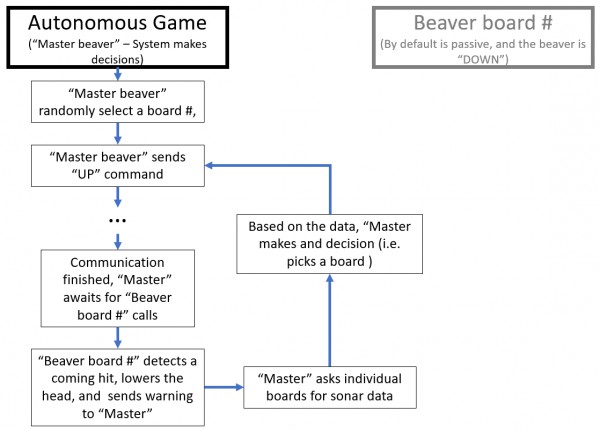
Game flow
And the final video!
Add bluetooth
I tried to add bluetooth (HM-11 module) to the master board using Neil's example. But for some reason the module does not answer back... It only asnswers when I type AT+HELP... but nothing more ... I'll try after the finals week...
Interactive game: user makes the decision
For this, I'll design an APP so I can interactively select which beaver will move up. The same thing I did with the terminal above, but now with an GUI. I'll work on this ater I solve the bluetooth issue...
Files