Output devices
This week we were asked to add an output devive to a microcontroller board that we'd designed, and to program it to do something. Then, as a group, we had to measure the power consumption.
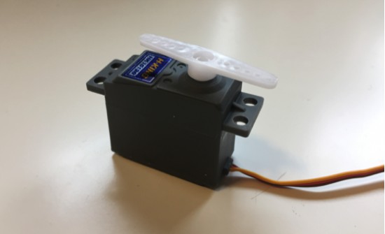
For the individual assignment I chose a servo motor. This week I also spent some time thinking in my final project, and how I am going to drive the beaver heads. Initially, I considered using solenoids: they are simple, and their control (simple on/off) suited my project. However, the ones I found had very small travel distance, and they tend to be pricy (I know... I could also design and make my own...). I did some research, and many real whack-a-mole games uses compressed-air cylinders, which is not an option neither. Finally, I decided to use a servo: it's small, cheap, and precise and simple control.
Starting simple: Neil's example
Since I had to build a board and program it, two things could have gone wrong. And the debugging process could have not been fun. We had Neil's example for both the board and the code, so I started simple and learnt from something I knew it was gonna work.
Neil's board example for servo motors
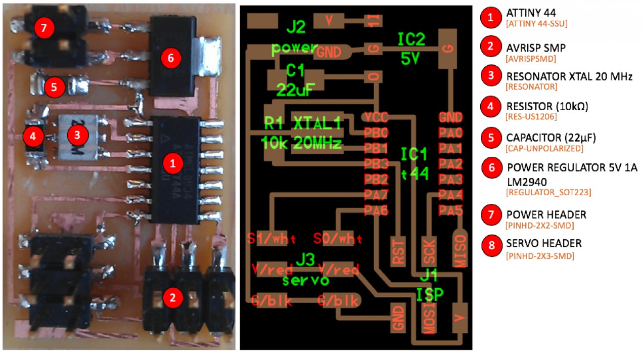
The board is quite simple. Pretty much another version of the hello-world board. But this one also included a power regulator (5V - 1A), a higher capacity capacitor (as requested by the power regulator data sheet), and two additional pin headers: one for the exernal power, and another for the servo. The power regulator was needed because of the servo power consumption (perhaps the USB is not enough anymore...). Also, now we can have an external battery and take our board wherever we want :D
Further inspection of the servo header revealed that servos need three channels: power, ground, and signal. The latter is given by Pulse-Width Modulation (PWM). After I stuffed the board, I flashed Neil's code and voilà!
.Finally, I measured the power consuption using one of the power supplies (PS) in the shop. For this, I basically plug the PS into the board, picked the voltage (5V) and the maximum current (1A), and pressed OUTPUT. Then the PS supplied the power, and showed how much current my device was drawing.
.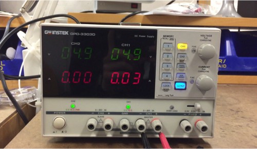
My servo motor worked under 5V, and the PS showed peaks of about 0.5A everytime the motor moves.
Programming the board with Arduino IDE
After I checked the board worked, I tried to program it with Arduino IDE. Initially, I tried to avoid to learn what PWM was. There are (at least) a couple libraries that control servos in Arduino (e.g. SoftwareServo.h, Servo.h). None of them worked for me...
I spent 2-3 days trying different codes, checking what other students did in the past... nothing. I found someone using the function analogWrite() to send the PWM, but since I didn't understand what PWM was, I couldn't make it work neither... My motor was shaking, always going back to the same postion...
Resigned, I started to research about PWM... I looked into Neil's code, and also watched a couple of tutorials about servos and PWM (Paloma recommenedthis one). It's actually really simple... I should have started with this. Anyway, here is my code:
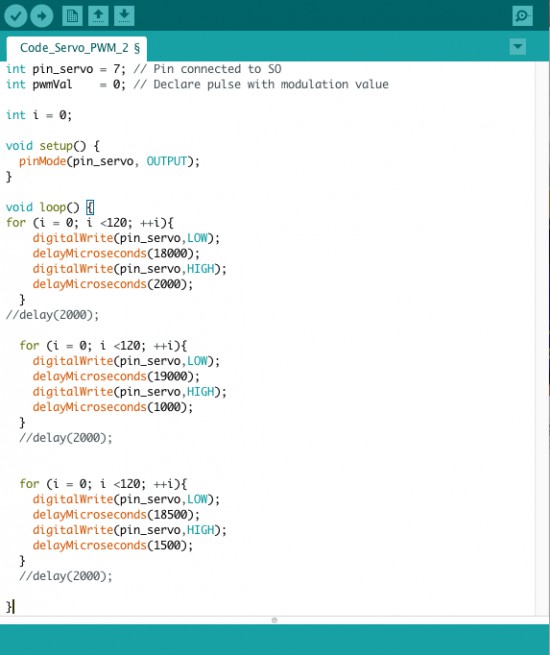
Arduino code for servos (PWM)
Multi-porpuse board: read a sensor + control an output
Once I learnt how to build the servo board and to program it, I designed my own board. For this I wanted to combine the input and output assignments: I'd build a board that reads a sensor (in this case a sonar) and reacts to it by controlling the servo. I also included a FTDI header. For my final project I'm planing to build individual boards for each beaver. Each board will read a proximity sensor (most likely a sonar) and control the beaver head actuator (most likely a servo). Also, all the boards have to communicate among them (hence the FTDI header). Here is my board:
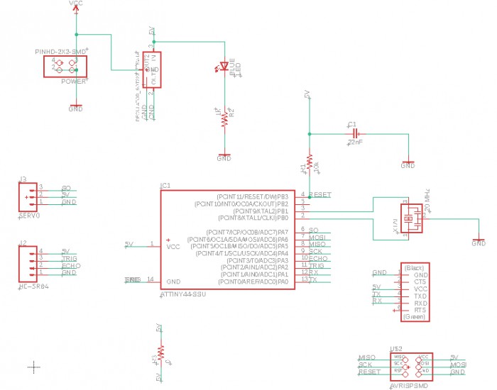
Beaver board - schematic
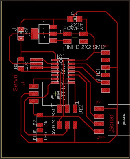
Beaver board - traces
And here a video of the board controlling the servo (with my Arduino code!):
Final project: shy beaver
I run out of time for this, but the plan was to build a platform/structure to test the mechanism that drives the beaver heads. This platform'd also accomodate the sonar. And the idea is to program the ATtiny so the head retracts if the sonar detects something closer than X cm...
I built the structure, but the mechanism is not ready yet... Come back next week!
Files