 Amnahir
For my final project, I am making a dress that lifts the train while the wearer is running/dancing. After they have stopped running/dancing, the dress will lower again. I figured this would allow me to use many of the different weeks new knowledge, while also being something I am excited about. In the end, I used the following weeks assignments to help me in my final project:
| Week | Used | How |
|---|---|---|
| Week 1: Computer-Aided Design | Yes! | 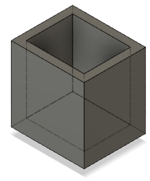 |
| Week 2: Computer-Controlled Cutting | Yes! | 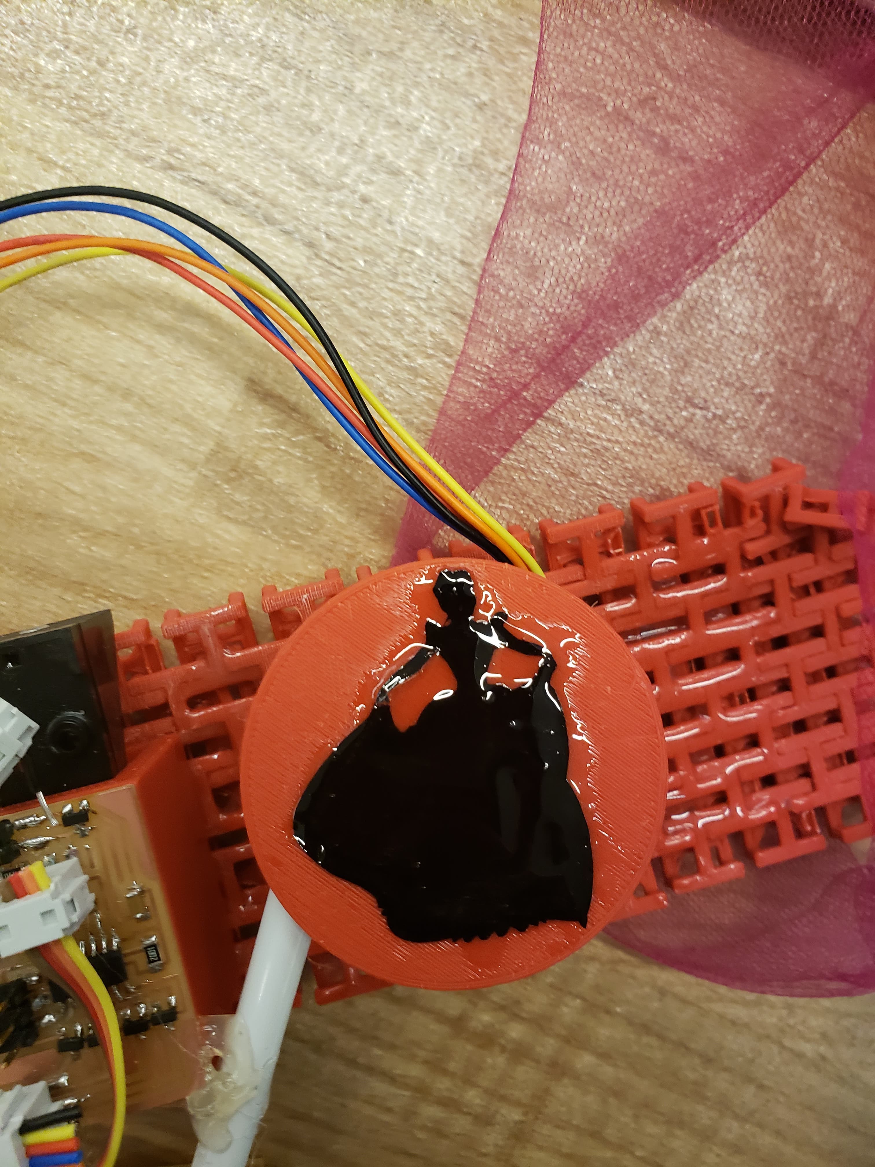 |
| Week 3: Electronics Production | Yes! | 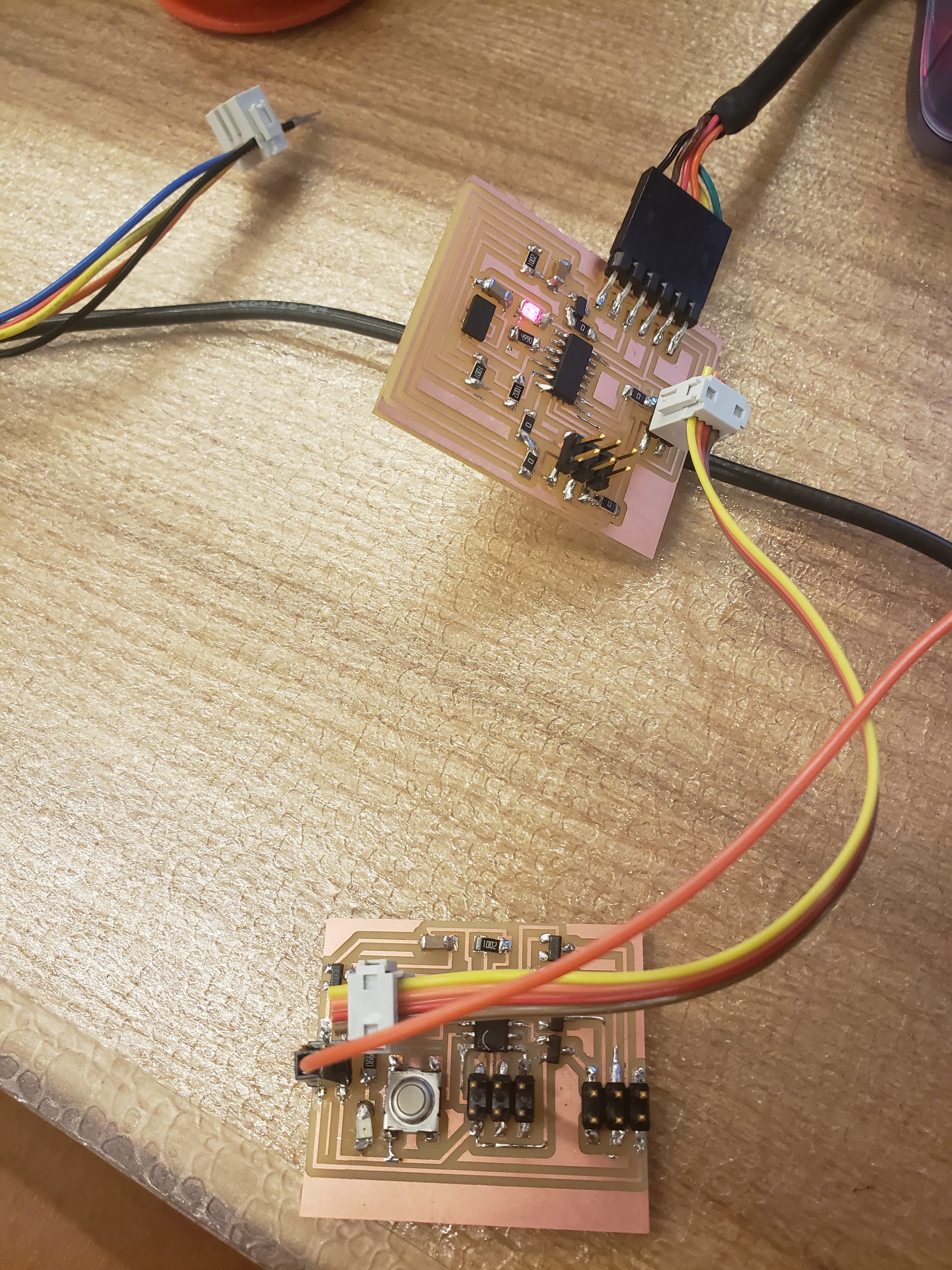 |
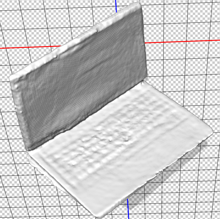
| Week 4: 3D Scanning and Printing | Yes! | 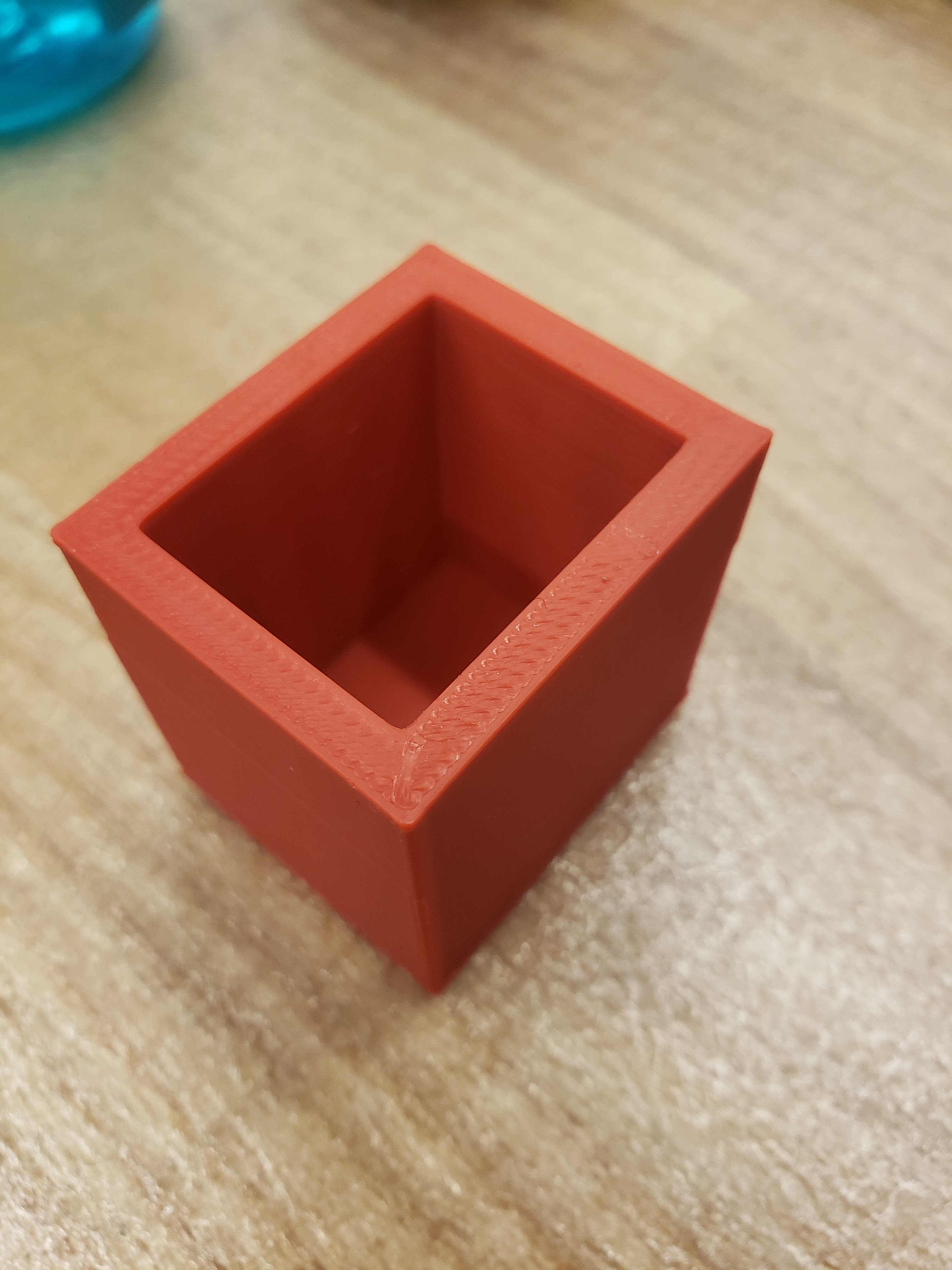 |
| Week 5: Electronics Design | Yes! | 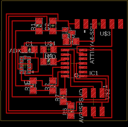 |
| Week 6: Computer-Controlled Machining | No | |
| Week 7: Embedded Programming | Yes! | 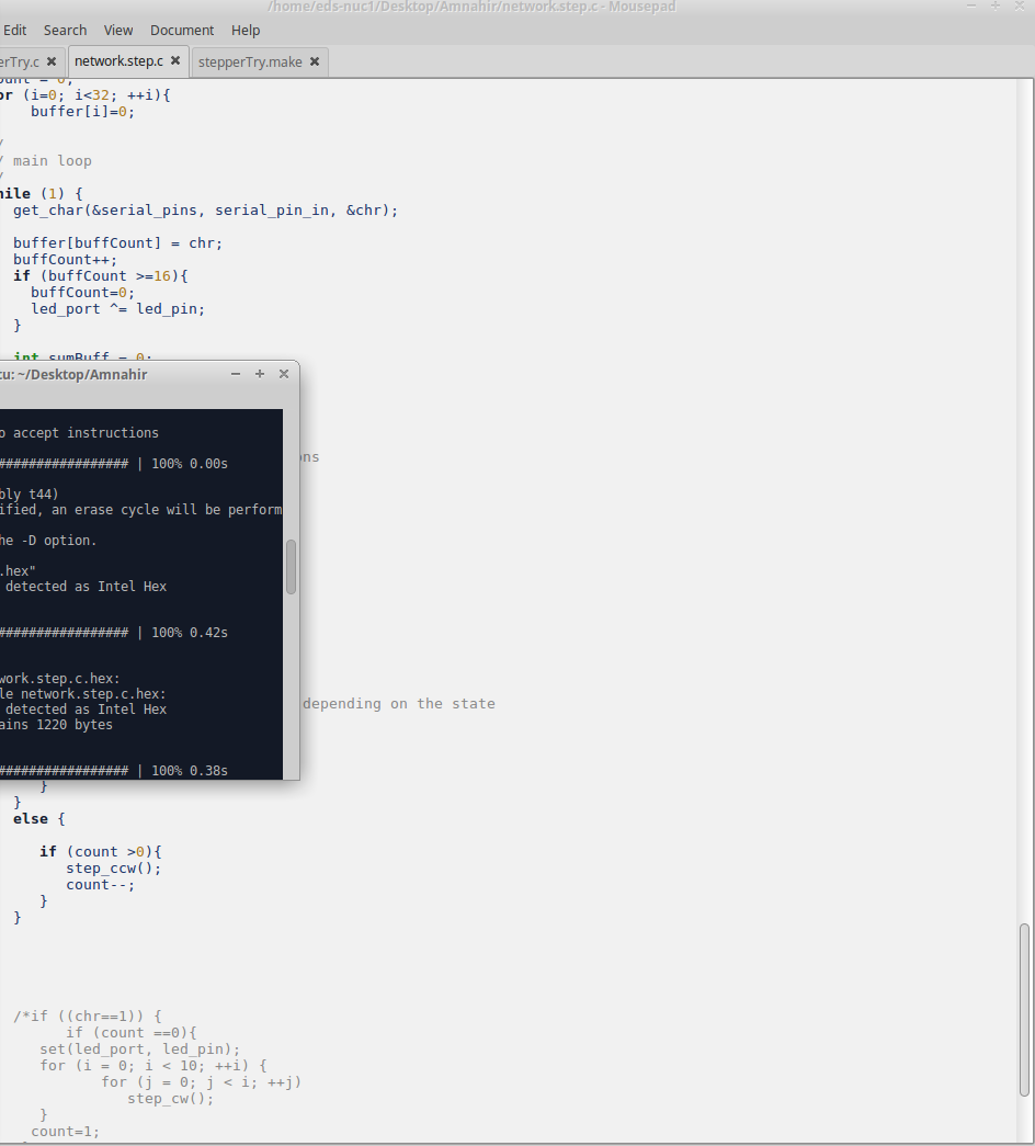 |
| Week 8: Molding and Casting | Yes! | 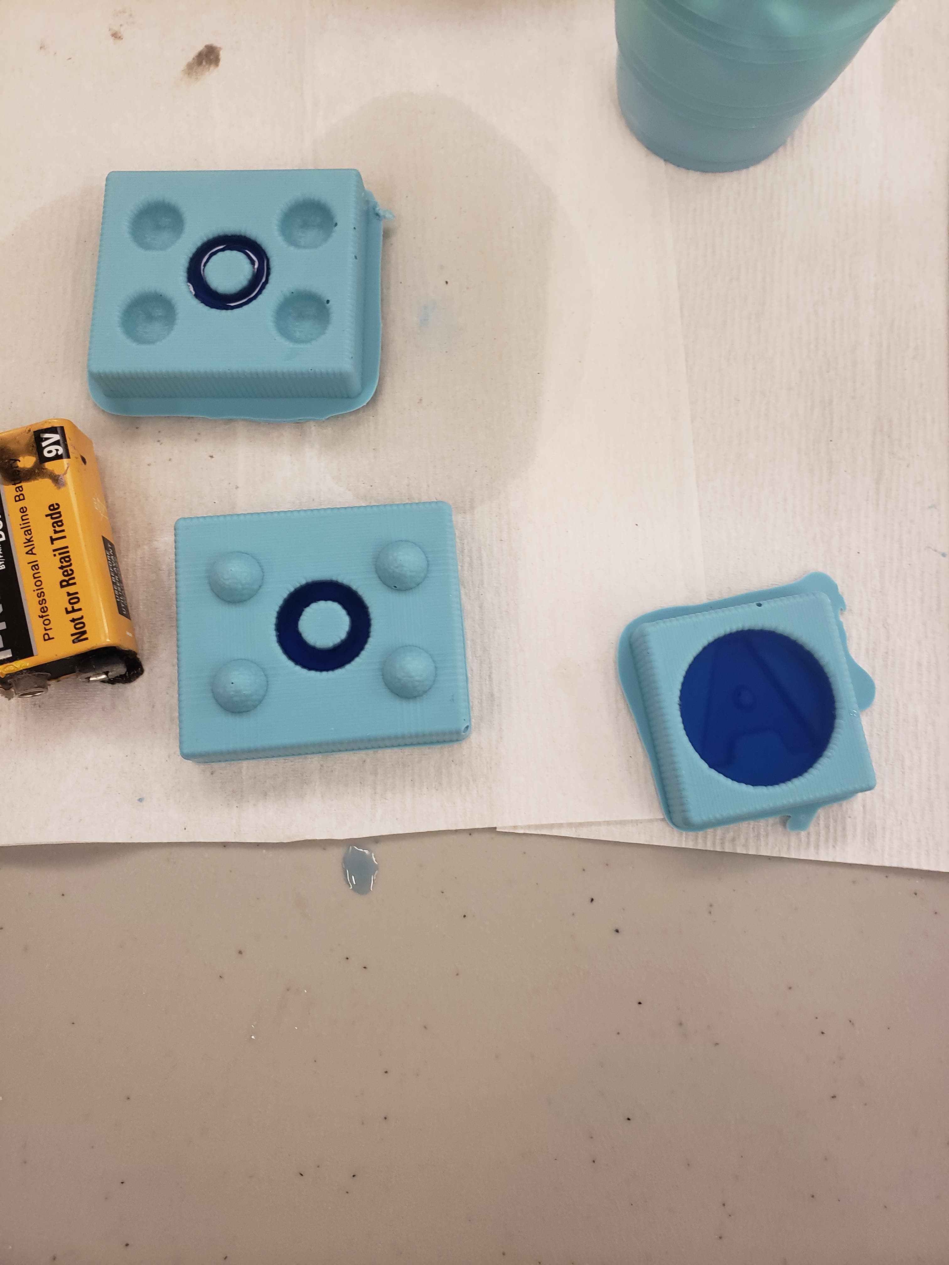 |
| Week 9: Input Devices | Yes! | 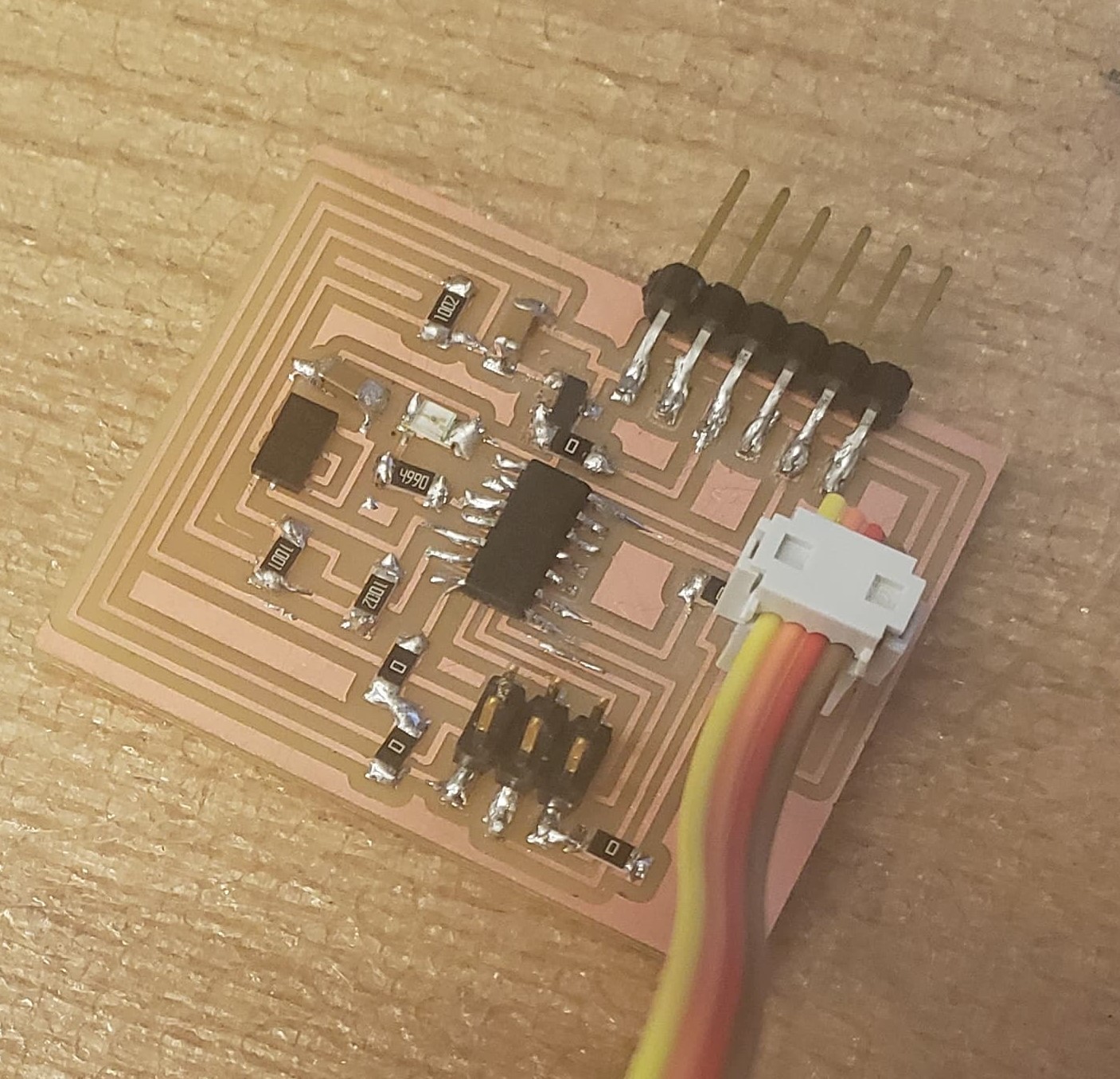 |
| Week 10: Output Devices | Yes! | 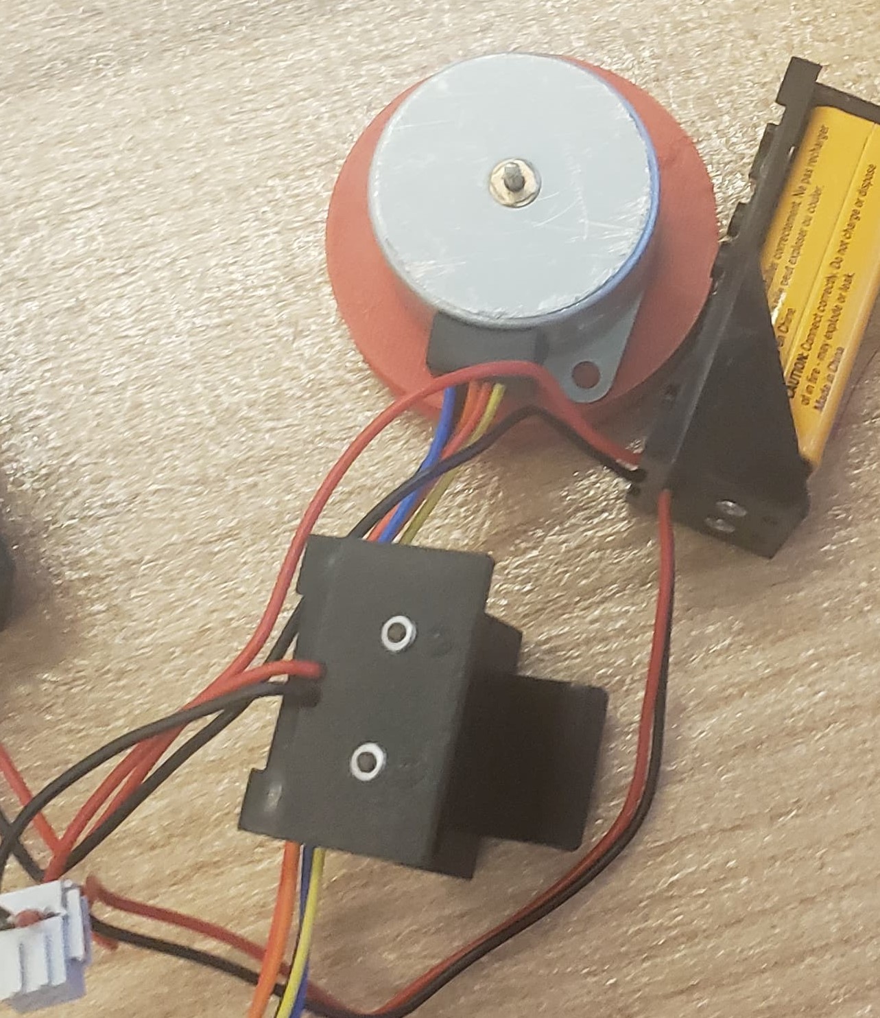 |
| Week 11: Mechanical Machine Design | No | |
| Week 12: Interface and Application Programming | No | |
| Week 13: Networking and Communications | Yes! | |
Now in more detail:
Networking:
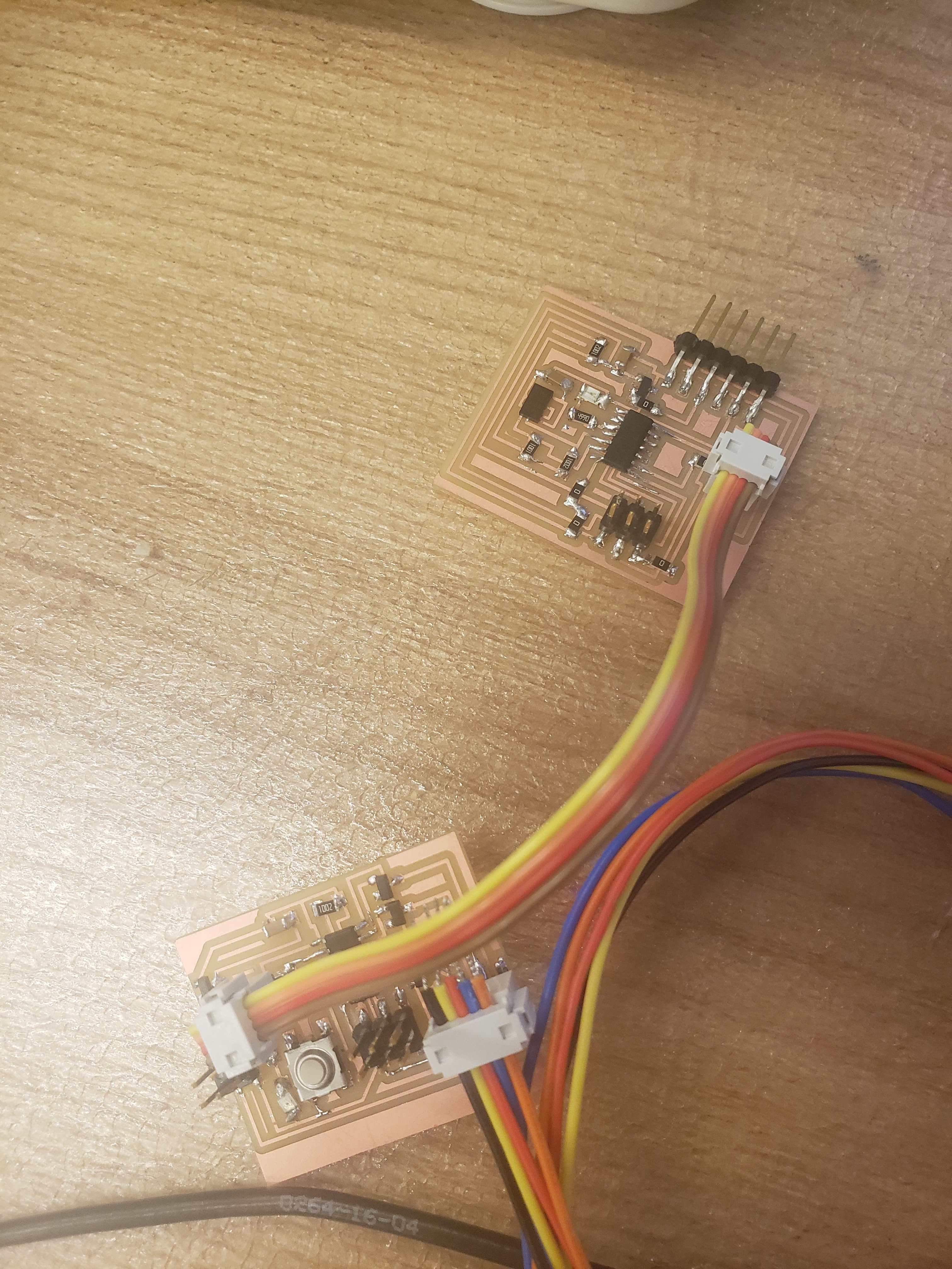
The first step in my final project during the final project week was to finalize the networking code between the accelerometer board and the motor board. During week 13, I was able to get the button controlling the LED on both boards. However, since I wanted the accelerometer to turn the motor on, I had to get this coding right. So that was my first job!
Although I could get the boards working with the button, I couldn't get the accelerometer to turn on the motor. I tried simplifying the problem and just getting the accelerometer to turn on both LEDs. After struggling A LOT(!!!!!!), I gave up and asked Ben. It then turned out that my previous code wasn't working properly... It looked like it did what I wanted, but wasn't using proper communication. Apparently, I just didn't really understand how networking worked. I had been creating one program, which had the everything included. For example, I had the accelerometer, motor, LED 1, LED 2, FTDI, serial_input 1, serial_input 2, etc. all in one code. I figured they were both programmed with the same code and somehow the ATTinys communicated with each other.
So, Ben helped me out a ton explaining that I had to program each board separately. They communicate by sending values through the put_char function and recieve values using the get_char function, which I had previously been using to send info to the computer for python code. But this still wasn't working...
So we took out the oscilliscope! At first, the graph looked really disorganized and random. But in the end, we had switched the polarization of the oscilliscope, zoomed to the proper amount, and re-programmed the code that is used for th python script which allowed us to see that it was sending the data. So, we looked at the stepper board. It seemed to be getting gibberish, so we spent a long time thinking about what the issue could be.
Speaking with Jackie, the Architecture TA, she mentioned that one of the possible problems was that I didn't connect the Tx of one board with the Rx of the other, and vice versa. I mentioned this to Ben and we worked through my wiring to make sure that it was all ok. It turns out that this was part of the issue. I finally understood that the Tx and Rx wording was confusing since sometimes it was in the FTDI point of view and sometimes in the ATTiny point of view. So I figured out that the Tx of the FTDI connects with the ATTiny Tx of the first board (all of this in the point of view of the FTDI), but then I need that to connect with the Tx of the second board (in the point of view of the ATTiny on the second board) or the Rx of the second board (in the point of view of the FTDI). All of that sounds super confusing, but after thinking about it for wayyyyyy too long, I figured it out and got the proper connection.
Using the oscilliscope, we figured out that this still wasn't working. So I went back to my Eagle schematic for the motor board, and noticed that I had inputted the wrong pins for the Tx and Rx. Once I replugged in the accelerometer board to the to the proper pins, the oscilliscope showed that I was getting something from the accelerometer!!!!!! Since I wasn't exactly sure what values were being sent through the original code, I changed it so that it would send a 5 every 500ms. Shockingly, the oscilliscope told us that that is what the stepper board was recieving. I finally had communication between the two boards! Since I had struggled so much, I decided to leave the code running to when the stepper gets a 5 the LED turns on!!!!!!
Working Motor:
In week 10, I was able to get the motor spinning. So I came into the final project thinking that nothing was going to go wrong, once I figured out the accelerometer code for the networking then I would be done. But it turns out that once I made the spindle, I saw that the motor jitters a lot as opposed to moving in a smooth continuous movement. I resoldered everything a billion times, and still couldn't fix the problem. I had no idea what was wrong in this situation... At first, Ben suggested that I wasn't getting enough of a voltage to the motor. However, using a multimeter, I measured that the motor was constantly getting 8.3V from the batteries. I then tried adding 3 9V batteries in parallel hoping that the voltage would remain stable for longer. Sadly, this didn't work. So I tried connecting the boards to a power source. Again, the motor was very shaky at 9V, but it seemed to improve a little at 12V. Sadly, after a couple minutes, the power supply still didn't let me go in both counterclockwise and clockwise one after the other. So, I ruled out the power supply as the problem.
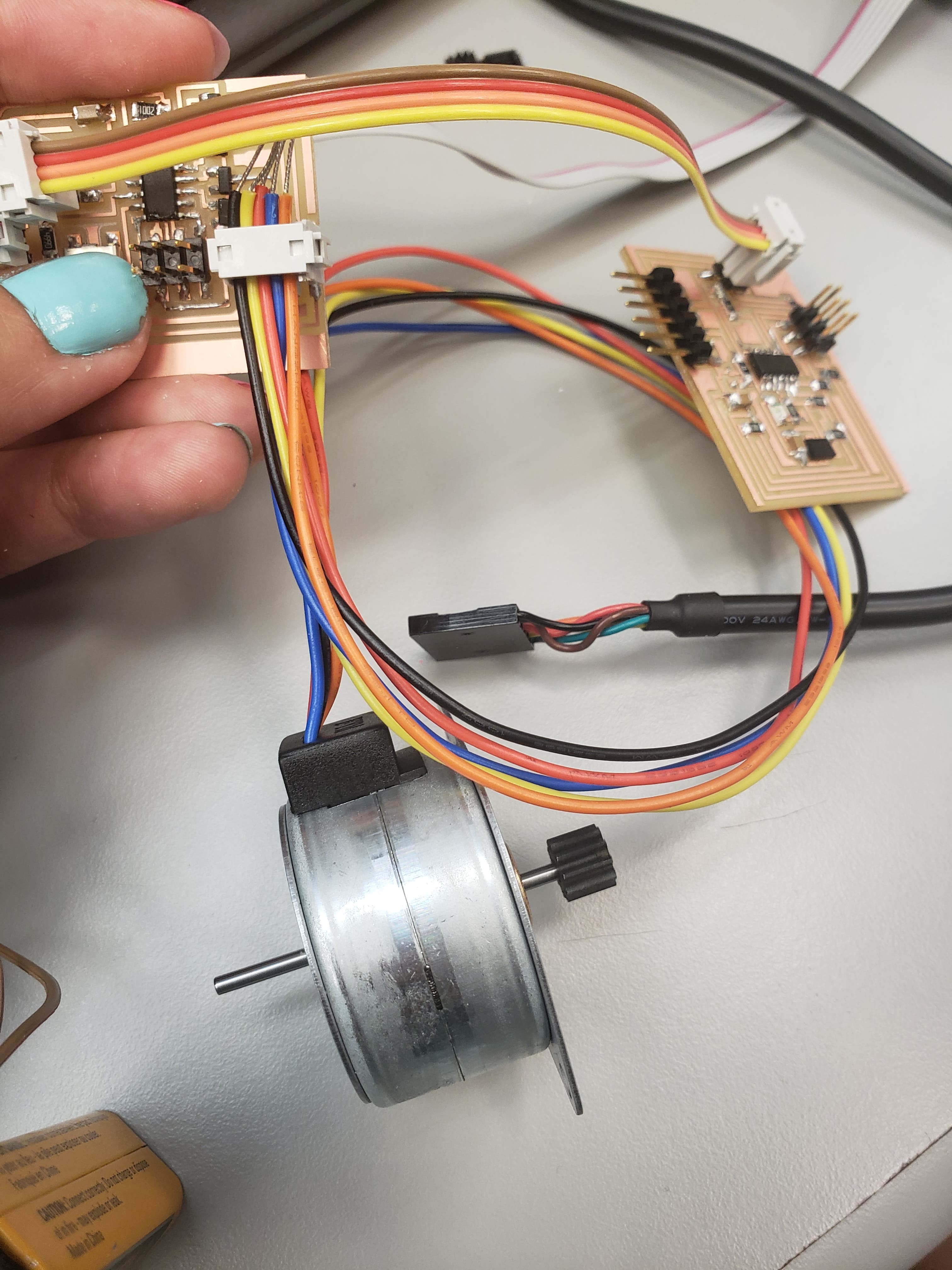
I resoldered everything a million times to make sure that there were no shorts, but I couldn't find anything. I also tried all iterations of the motor turning one way and another through the code. I also added a second of rest before changing directions, so that the motor had time to "reset". But none of that was helping the problem. After that, I decided to recheck all of my pin connections from week 10 and the online resources that I had found. After hours looking at the code and pictures, I realized that I had accidently switched the pins for the "brown" and "black" wires during one of the iterations of changing my code. Once I fixed this the motion became smoother and was working!!!
But then..... I came in the next morning and it didn't work again. 😭 It essentially became super jittery again, and couldn't switch from one direction to another. Although it would change directions if the motor was standing horizontally versus vertically. I had no idea why this might be the case, and was really confused by the problem. Also, I randomly changed the code, this allowed me to get the motor to move clockwise. After some time though, it would only be able to go counterclockwise. The direction that it could move kept changing, so I had no idea what the problem was... So I rechecked the pins I inputed in my code, by switching them back to their initial state, but once I did that the motor went crazy. So I switched it back. I also asked the issue tracker for advice. Based off of that, I added a 1 μ F capacitor to the motor. This sadly didn't make much of a difference but I kept it anyways.
Based off of the other suggestions, I went through the code again to see if I had to switch the order of pulses in the code for counterclockwise and clockwise movement. At this point, it would only be able to go counterclockwise. So I compared my code from that on the online resource I found. In the end, I found no differences. But just in case, I changed the order and reprogrammed the board. However, nothing seemed to be fixing the problem.
Finally, I asked Zach if he had anymore advice, which he recommended checking the board for shorts. It turns out this was the issue the whole time.... During one of my resoldering sessions, I had created a short from one of the MOSFETs connected to the motor. Once I fixed this, the board could go in both directions again!!!! It still isn't the smoothest motion, however, based off of my googling, I learned that stepper motors are never that smooth. For that reason, I decided it was good enough for my final project.
CAD and 3D Printing:
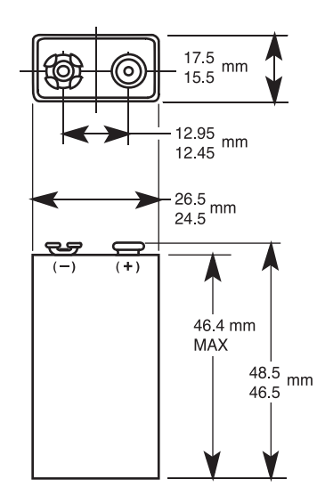
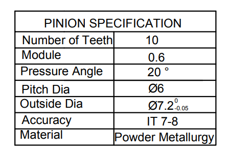
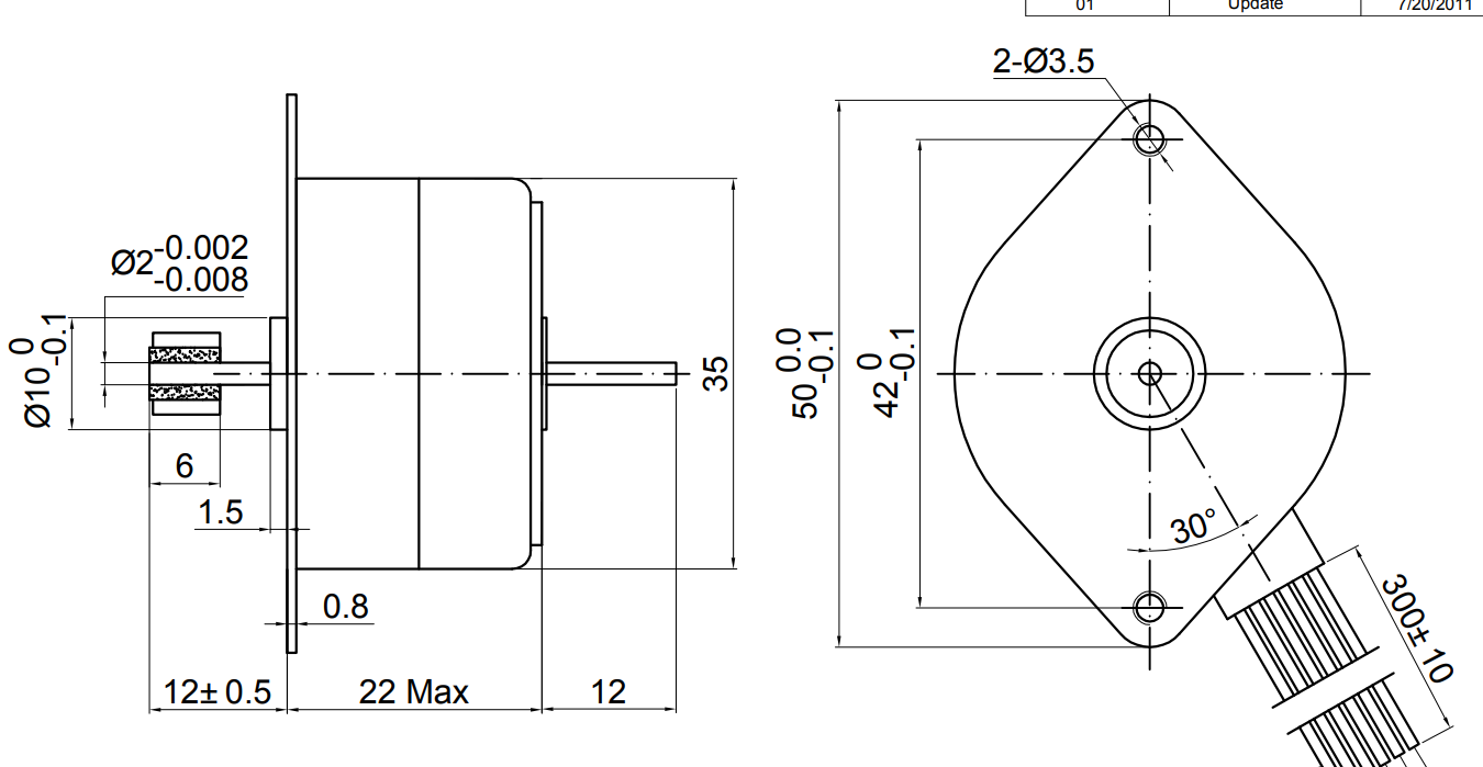
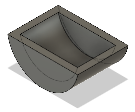
For my project, I needed to be able to hold the motor and the battery in place while wearing the "dress". As such, I chose to make holders for them. I used the dimensions found on the datasheet (shown below) to figure out the size of the holders that I could make. I decided to go simple for the shapes. So only a rectangle for the battery and a semi-circle for the motor.
The final designs are shown below. All of the designs were created in Fusion 360. They were also printed in a Sindoh 3D Wox. On the first print, the battery holder fit perfectly with the battery and its battery holder for connections. On the other hand, the motor was 2mm too long. For this reason, I chose to scale it down to 96% twice in order to get it down 2mm. This thankfully worked out a lot better since I was able to fit the motor almost perfectly.
After creating the holders, I realized that I needed something hard for them to rest on. I decided to try to print the 3D printed fabric that I created in week 3. But, I made it much longer so it would fit across my front waist. The CAD and final product is shown below.
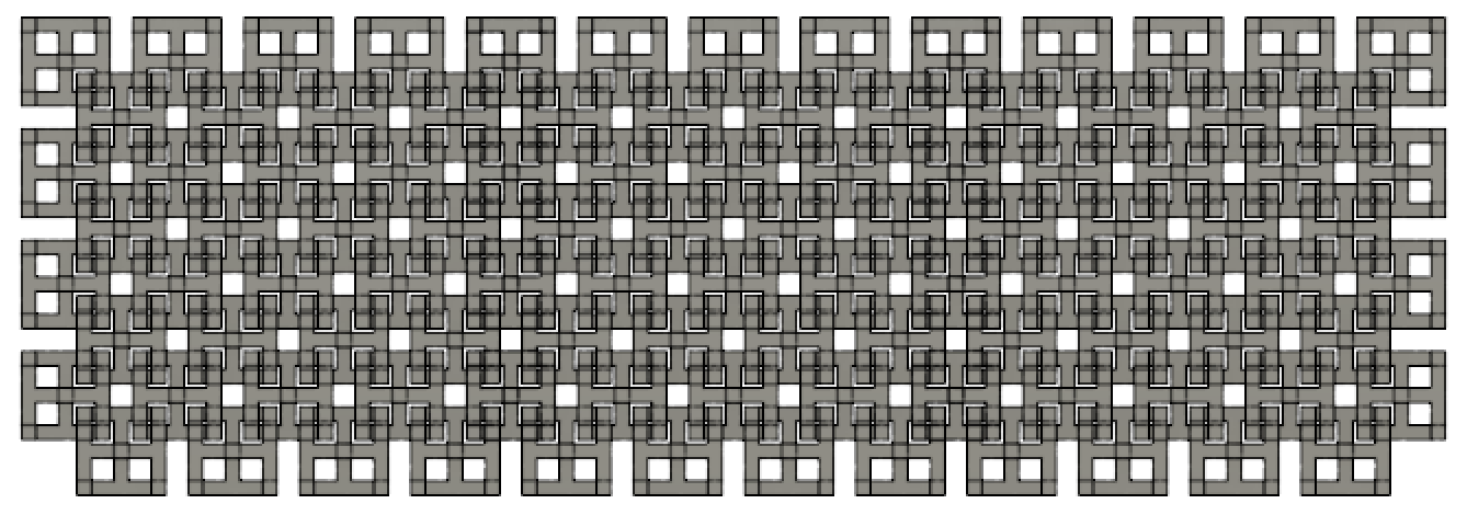
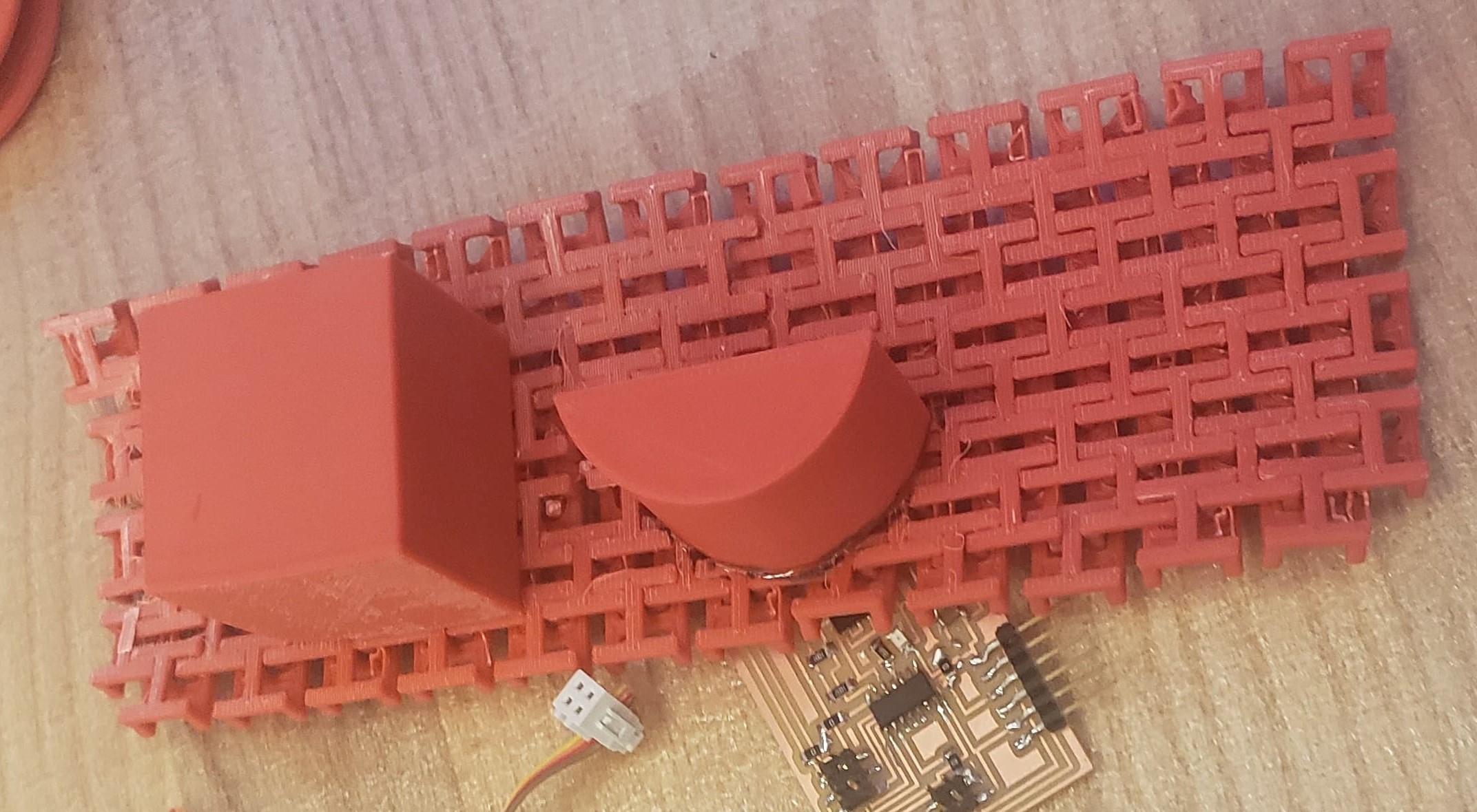
Although all of the pieces fit together well and created a good hold for the electronics, my choice in material was not great. I printed all of the pieces out of ABS. In week 3, I had printed the same "fabric" and it turned out really flexible and strong. This time around, with the exact same model, the product was incredibly weak. Many of the sections of the "fabric" broke while I was trying to bend the material and remove the scaffolding. For this reason, I regretted not printing it out of PLA again. Though I didn't have time to print it again, since the first try took 12 hrs, I used fast curing epoxy to glue together all of the holes. I used the same epoxy to glue the motor and battery holders to the fabric, which worked well to keep everything together. Although it is now less flexible than it should have been, the epoxy is strong enough that the final product can hold all of the electronics well.
Molding and Casting:
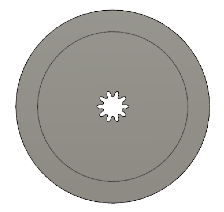
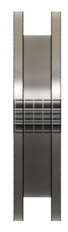
For my project, I wanted to make sure that the threads did not get caught in the fabric or knotted while moving up and down. For this reason, I wanted to create a path for it to follow. An easy way that I thought of was creating cylinders that will be placed a certain intervals along the skirt so that the thread remains inside. This would ensure that the thread does not entangle with the rest of the fabric or upon itself. Since I wanted to use as many of the weekly lessons as possible, I figured a good way to make these cylinders was through molding and casting.
I created the CAD file in Fusion 360, and then was able to mill it on the Roland SRM-20 mill with a 1/8" endmill. The rough cut had an overlap of 25% and the smooth had one of 80%. The computer was able to communicate through fabmodules. I was able to get the tool path quickly, however, the mill kept freezing up. For this reason, it took forever to start milling.
Once I did start milling, I accidentally broke my mold. When trying to move the endmill back to the origin, I forgot to bring it up to the highest z possible. For this reason, it cut a hole through a section of my wax. At the same time, it pushed the wax back before I could stop it. When I re-taped it and started the smooth path, it was off enough that I decided to restart.
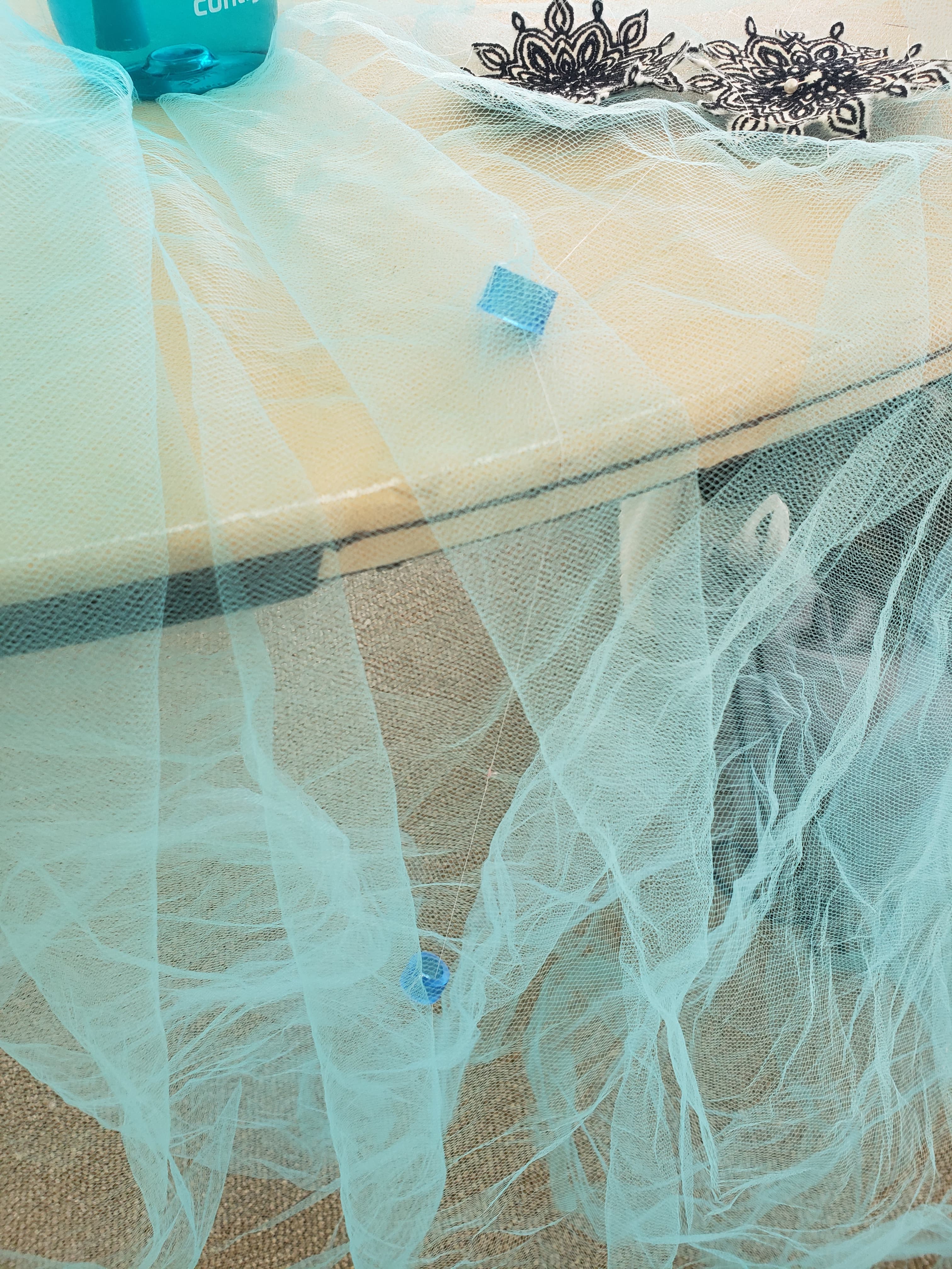
Thankfully, the second time around had no issues. I was then able to fill the wax with oomoo. Since I had problems with the oomoo drying slowly, I made sure to be really careful about weighing out the concentrations. However, it again did not work out, and it took 3 hrs to dry instead of 1.5 hrs. Once it did finally completely cure, since I didn't want to repeat previous mistakes, I was able to cast my final product. I created the cylinders out of clear polyurethane, which I dyed blue with their Smooth On's color cast. Once done, the cylinders were perfect for my dress.
The cylinders were hand sewn on the fabric. I had to knot it in really well, since the first one fell off after an hour or so of testing.
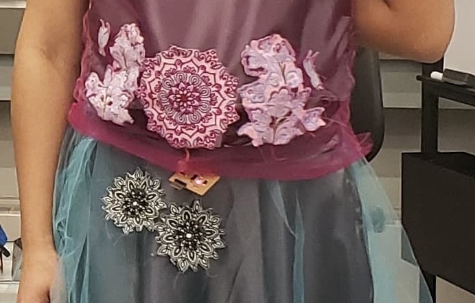
Embroidery:
Once I had made my dress, I wanted to add decorations to try to make the design a little nicer. For this reason, I sewed on all of the different embroideries that I made onto the skirt and the top. I tried to strategically placed the embroideries on the articles of clothing so that they would cover the electronics of the "fanny pack" and the ripped fabric. The final products of the embroideries are shown in week 14. The final sewn embroideries are shown below.
Vinyl Cutting:
For my project, I wanted to throw a shoutout for my inspiration. As everyone keeps telling me my idea is for the modern day cinderella, I decided to add a picture of her on the motor spool. I found an image on google, and using the GM-80 Roland vinyl cutter, I created a mini cinderella. Sadly, the vinyl wouldn't stick to ABS, so I used gorilla glue on top of it to get it to stay.
Turns out this wasn't the best idea, since apparently gorilla glue creates a lot of bubbles.... Since I didn't realize this until it was too late to cleanly remove the glue and vinyl sticker, I decided to just leave it and hope it didn't get too bad (which didn't really happen). So, in the final product, the cinderella isn't as easily seen 😭.

Optimal Fabric Weight:
Once I had sewn together the skirt and fixed all of the elctronic issues I had had, I then realized that the strength of the motor was going to be a problem. I initially wanted a two layer skirt for the dress, one was the light blue fabric and the second was a heavier grey fabric. Sadly, the motor was unable to pick-up the heavier grey fabric at all. The motor would just start to freak out again. So I had to use only the lighter blue fabric.
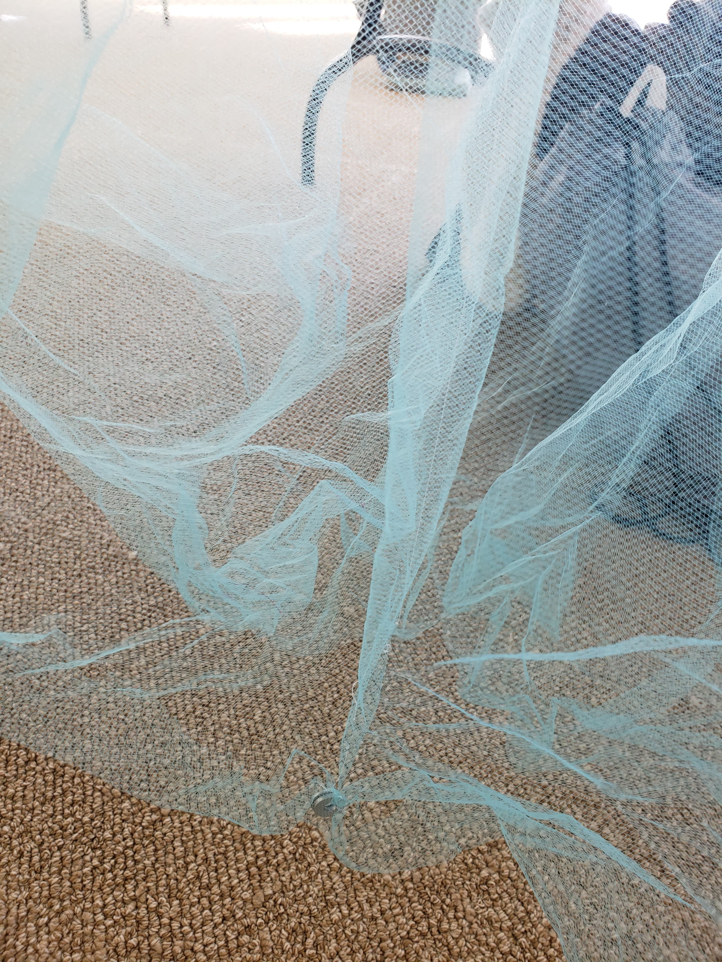
However, the light blue fabric turned out to be too weightless. Once the fabric lifted up, it wouldn't lower enough for the motor. So, the string would get stuck behind the spool or around it, leading to a lot of issues getting everything to work. I then realized I just needed to make sure that the fabric does in fact drop. I initially tried using a gear shaft to weigh it down, but this was too heavy and the bottom would not lift.
In the end I decided to sew on washers since I could easily control the weight. I added 5 washers and this turns out to be too light, so I then added 2 more. This turns out to have worked perfectly and the weight control was no longer a problem.
Fixing the Spool Tension:
While working on the lifting of the dress, I also noticed that the string wouldn't alwyas wrap around the spool. Most of the time it gott stuck behind the spool on the motor shaft. This caused the motor to freak out, and even if it didn't, the skirt would not lift a lot, since no enough strin gwas being grabbed with every turn of the motor. Asking Ben if he had suggestions, he mentioned that I had to fix the tension and ensure that all the string lined up perfectly with the spool.
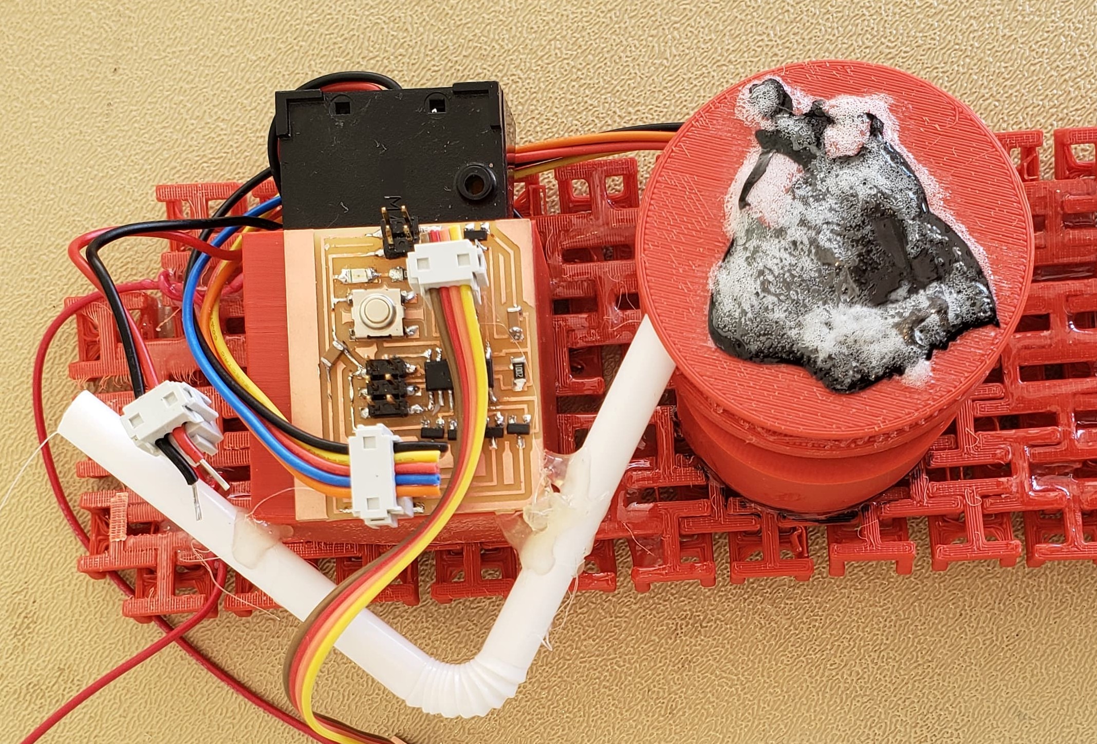
I tried of placing the "fanny pack" in a better location. However, this didn't seem like a possible solution, since the string is right against your skin and the motor won't run if the spool is against your skin. So I thought of adding another cylinder to guide the string to the spool. I was debating doing another molding for this, however, I was just finished with lunch when I noticed that the shop had bendy straws. I figured that this would work well, and would be incredibly light and thing (which isn't possible with the molding/casting). So I decided to glue the straw to my battery holder and position it so that it threads to the spool.
It now works really well, but the ideal case is when the device is worn. This is because if the straw and spool as pushed too close together the straw gets stuck on the hot glue holding the string to the spool. As such the motor is unable to move (which was shocking since I first thought it would just break the straw). Since this is an easy fix just requiring not concave alignment of the 3D printed fabric, I was happy with the straw!