 Amnahir
For the fifth week, we had to design our own circuit boards. We were given an initial board picture, which we were supposed to mimic. We then had to add a LED and a button wherever we wanted on the circuit. Since I had been using Fusion 360 for all of the CAD assignments, I decided to create the circuit board on Eagle. Although it seemed like the program was pretty simple, this took a lot of time as I was struggling to understand how to insert all of the downloads that were uploaded on the class website. At first I didn't think we could download them, and was trying to find each piece separately. Then after spending a couple hours struggling with everything, I managed to download all of the processes and add them to Eagle. So, I finally had access to all of the different components that I needed for the assignment.
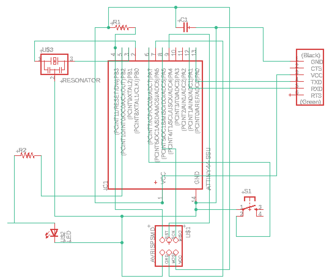
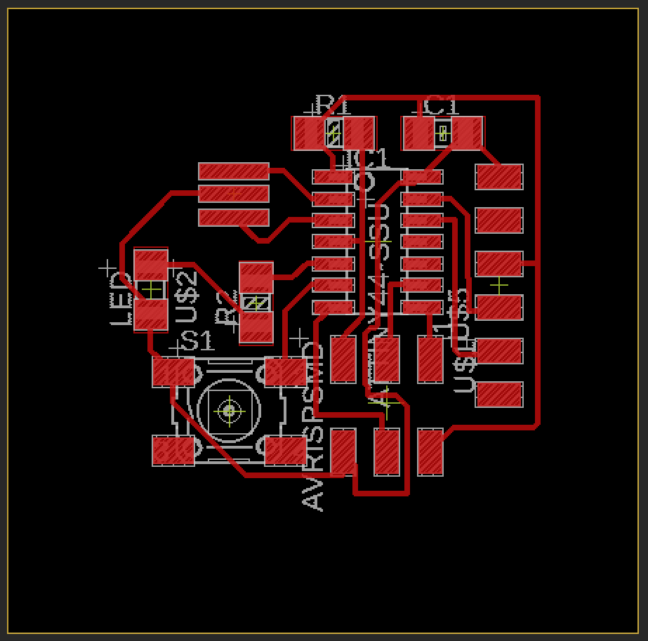
Once I had the components, I was able to pseudo self-figure out how to wire everything up. We had been explained it in class, but I struggled to remember exactly how everything worked. So I combined all of the components, and figured out how to use the class design requirements. So I needed traces of size 12 for the requirements to be fit. At the same time, red marks showed up when traces were too close together, which was super helpful which designing. My schematic and design file are shown below.
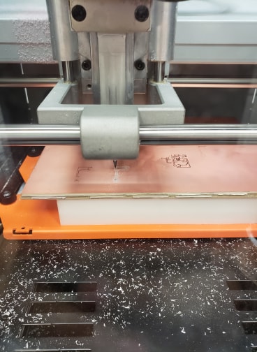
I used the Roland SRM-20 mill and had to reset the images multiple times, as the dpi setting was off. I would export the image from Eagle at 1000 dpi. However, I would have to set the dpi on the mods to 2000 otherwise the board would be twice as large as required. At first I didn't consider this as a problem that I would have, since it had only been mentioned for macs (I have a PC). But it turns out that that was the problem for me too. In then end, I got it milling, which is shown below.
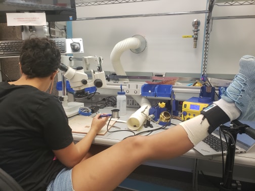
Another problem that I faced was I had only a short amount of time to work on my board. I had to put off working on the board, since I injured my ankle on Thursday. Since I couldn't walk without a knee scooter and couldn't wear a shoe (my foot was too swollen), I thought I wasn't allowed in lab. As I didn't heal in time, I ended up having to work while still injured, once I could wear a shoe. This involved trying to get around the tight spaces in the lab on a knee scooter, while also trying not too hit too many people or things. I also have to elevate my foot while I work, so I was forced to do this while soldering. I ended up getting all of the right components based off of the image above. In order to test the piece, I used a multimeter and measured the resistance between different components and solder joints.
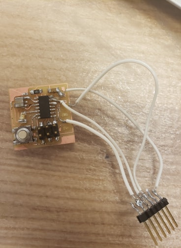
This was an incredibly tiring week, as the first board I made kept failing miserably. Through testing each solder joint separately, I ended up having to re-solder every single aspect. At one point, the FTDI component ripped off of the PCB with all of the copper pieces. Since the line for the mill was so long, I decided to keep working on this mill by using wires to connect the FTDI.
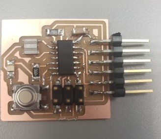
In the end, I was forced to mill another board. I made a couple changes to the board, which involved incorporating a resistor for the LED. I hadn't put one on initially since I wasn't aware that the LED needed a different voltage. But through the help of my other class members, I figured out that I needed the 499 Ω resistor. I also separated some of the traces, so that they would be farther apart and it could mill better. Thankfully this one did not prove too difficult to work with. I was then able to create a good board, which was tested.