 Amnahir
For the 13th week, we had to get two boards talking to each other. I decided to try to get this working for my final project using the boards that I had made in week 9 and 10. For this reason, I just remade my accelerometer board and the motor board with an asynchronous bus pins. This allows for easy communication between the two. I chose to have wired communication, since I wanted to start with an easy one, to see if I could get it working before trying something more complicated. At the same time, in my final project design, wired communication would work well, so I thought it was a good idea for accomplishing this weeks task.
Creating the boards was not difficult, as I only had to add in the other pins. Using the images on the class website, I was able to figure out how to connect everything pretty easily. I created the files in Eagle and was able to place the new pieces in the old boards without too much difficulty. I did have to add a 0 Ω resistor on the accelerometer board to get it to fit.
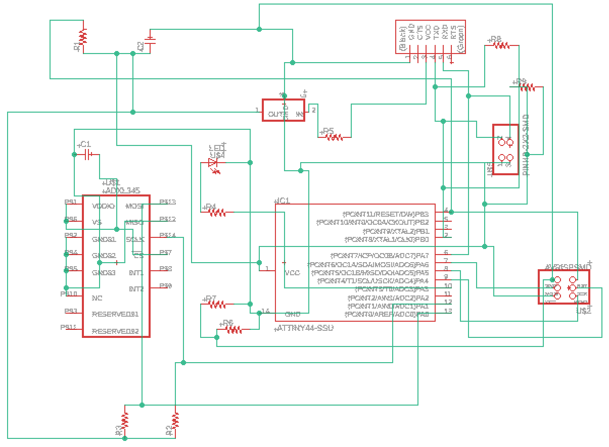
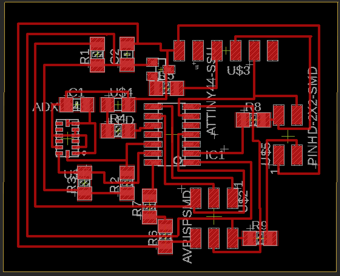
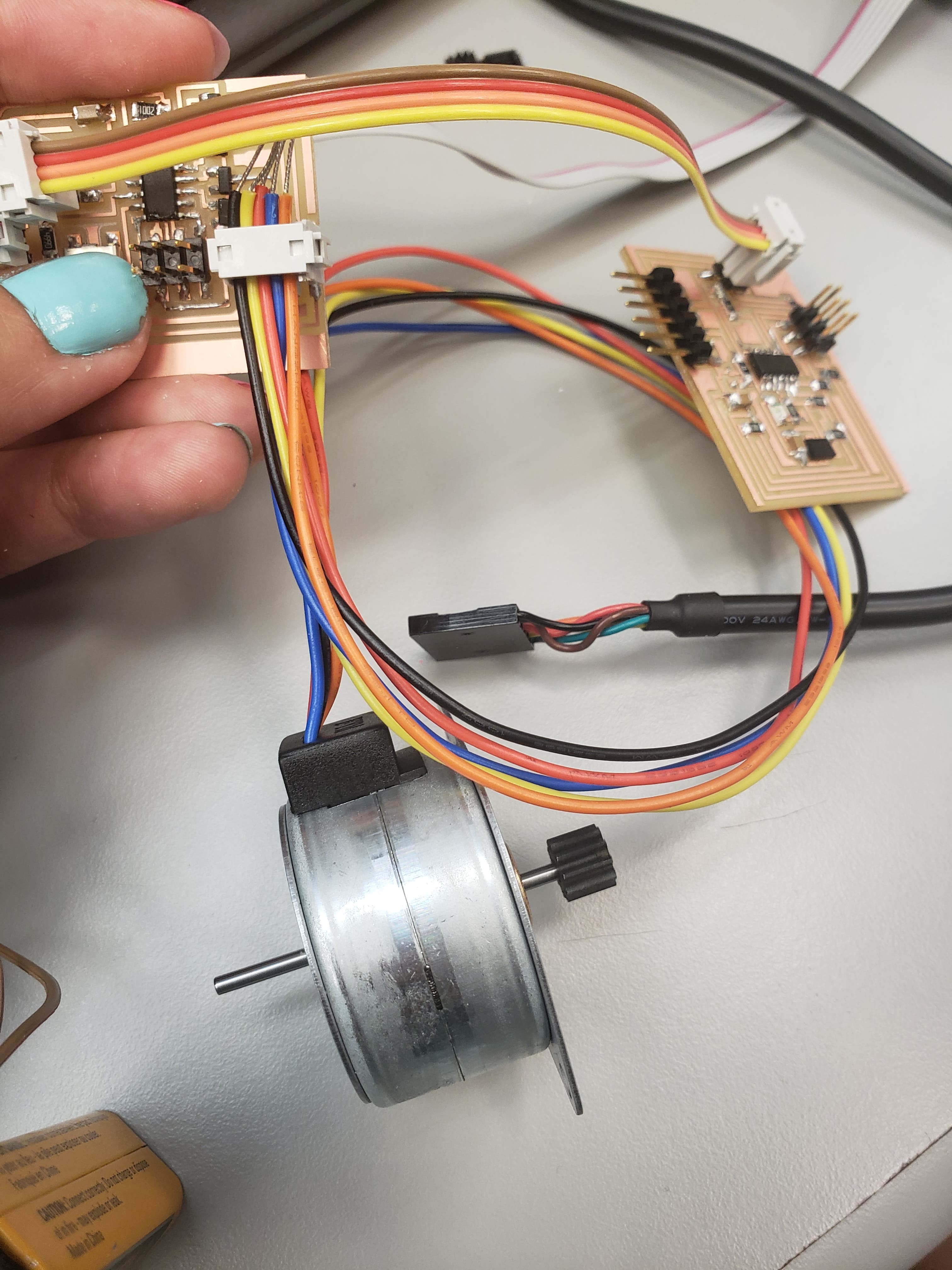
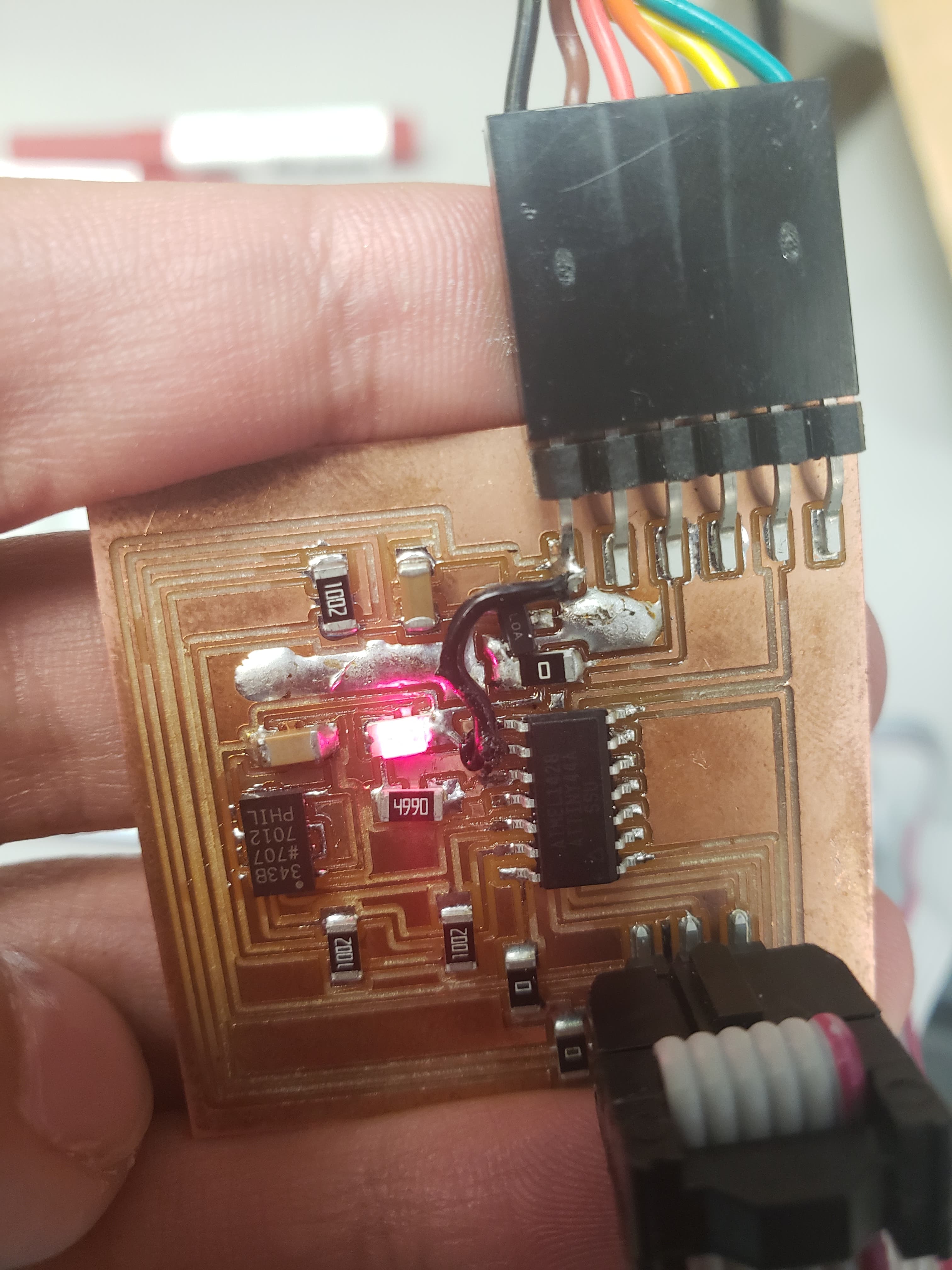
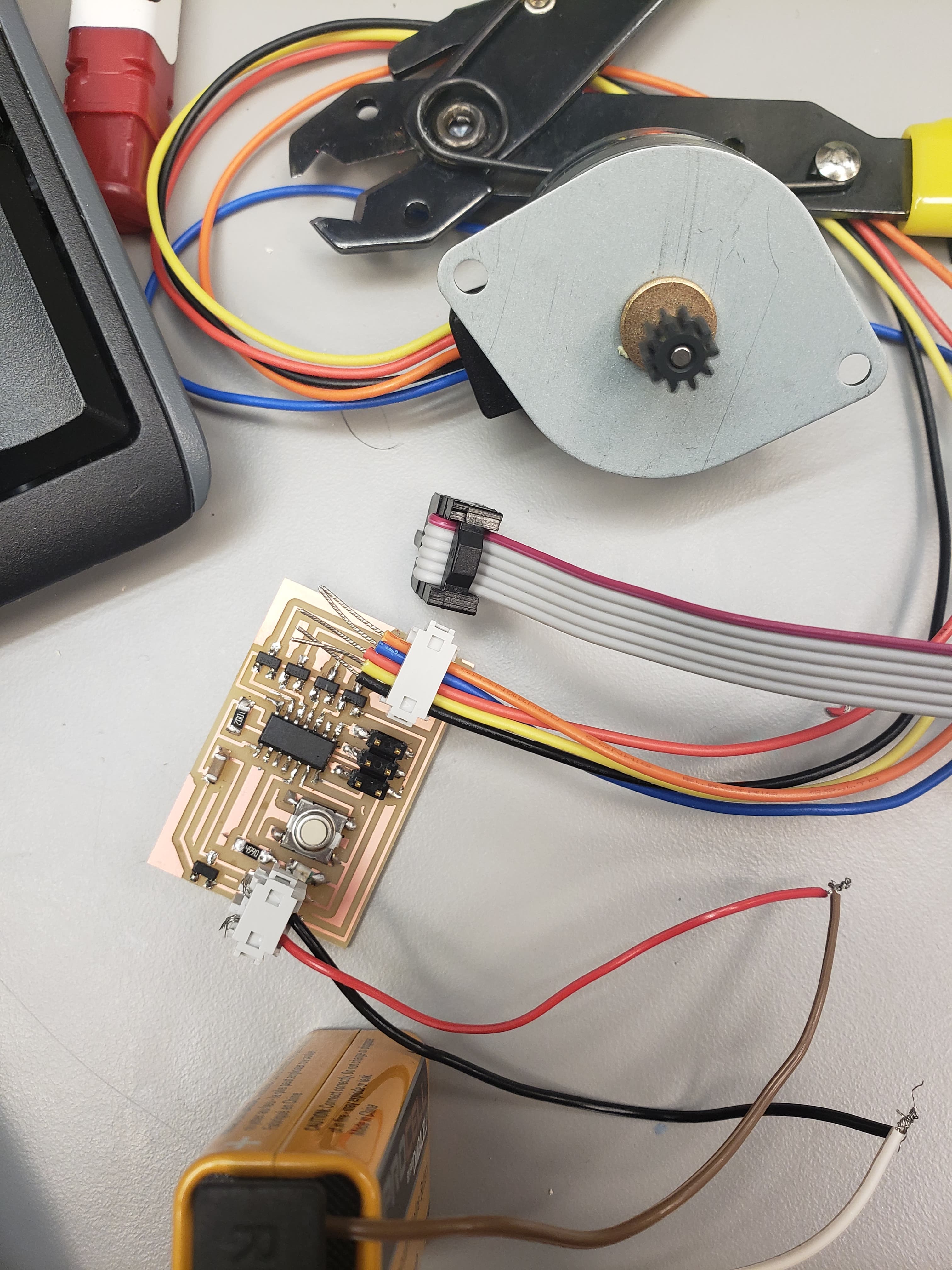
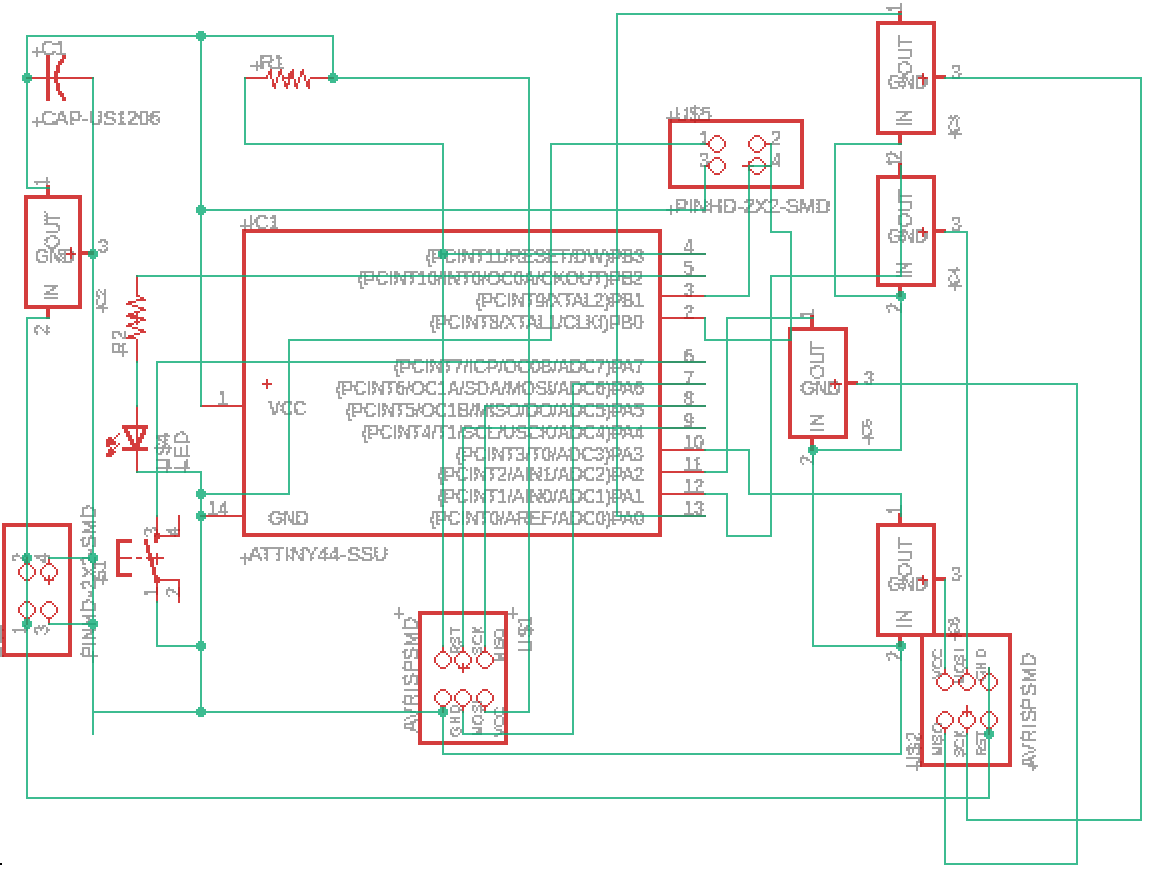
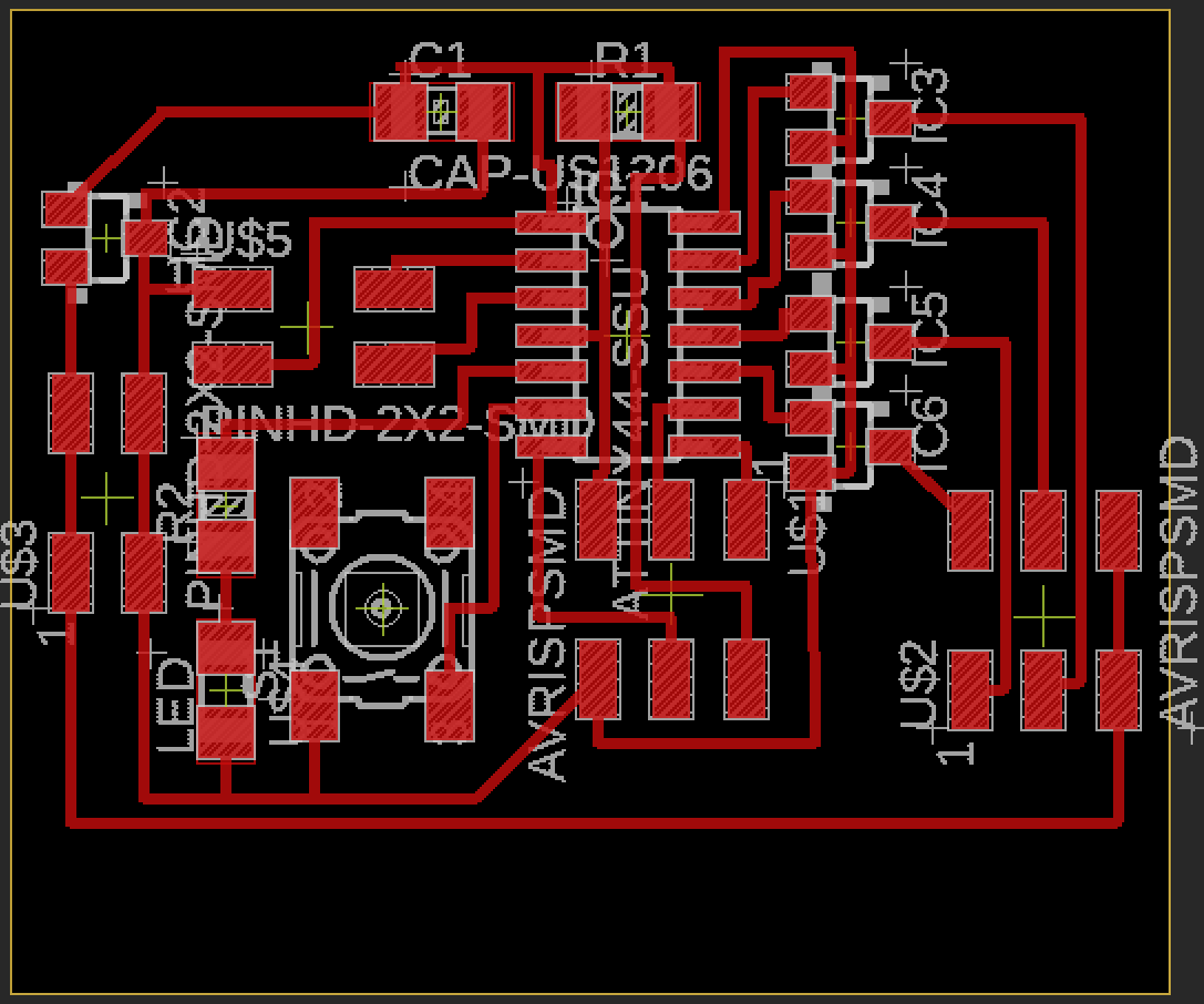
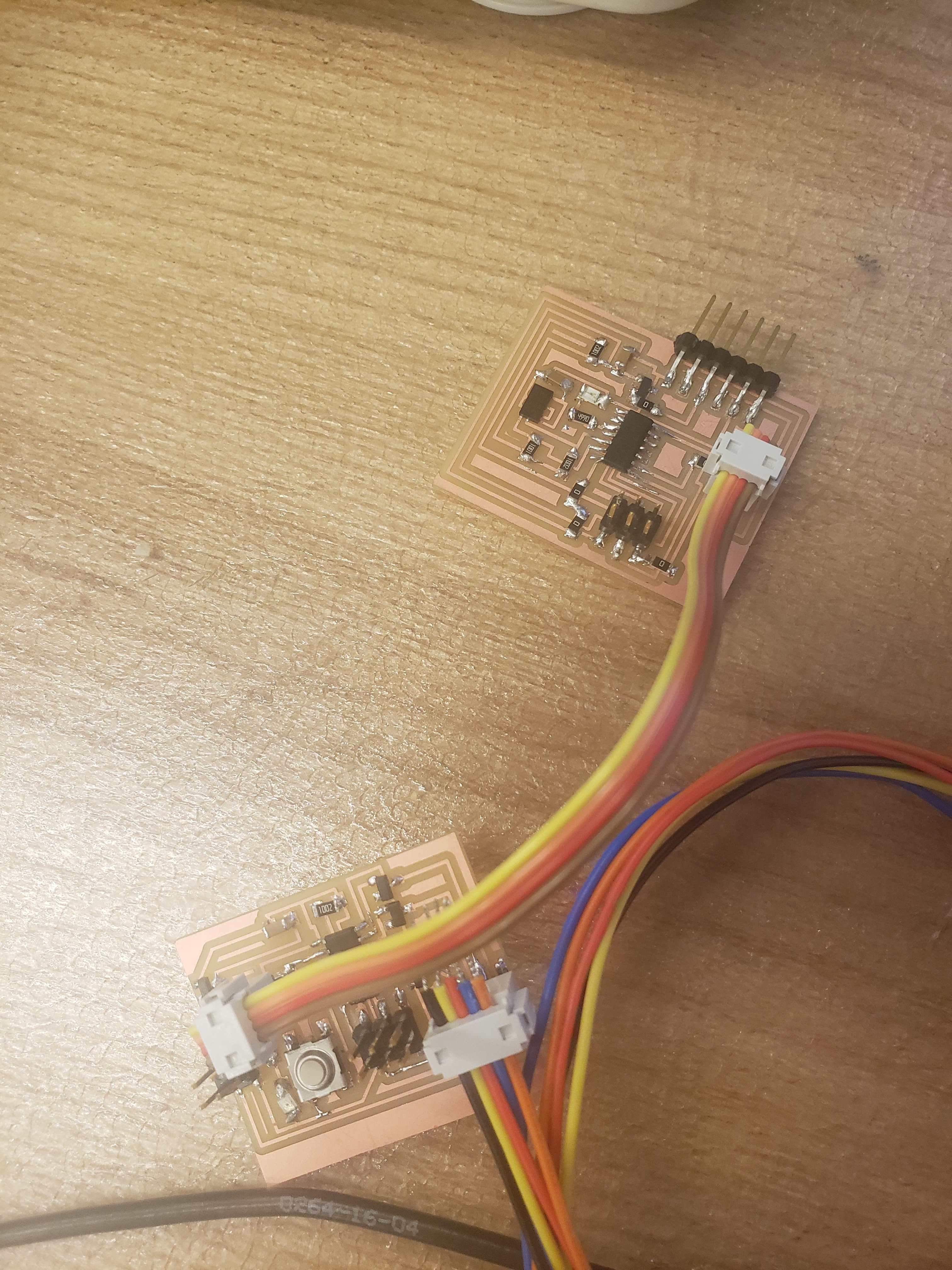
The accelerometer board and schematic are shown above. The unipolar stepper motor board and schematic are shown below.
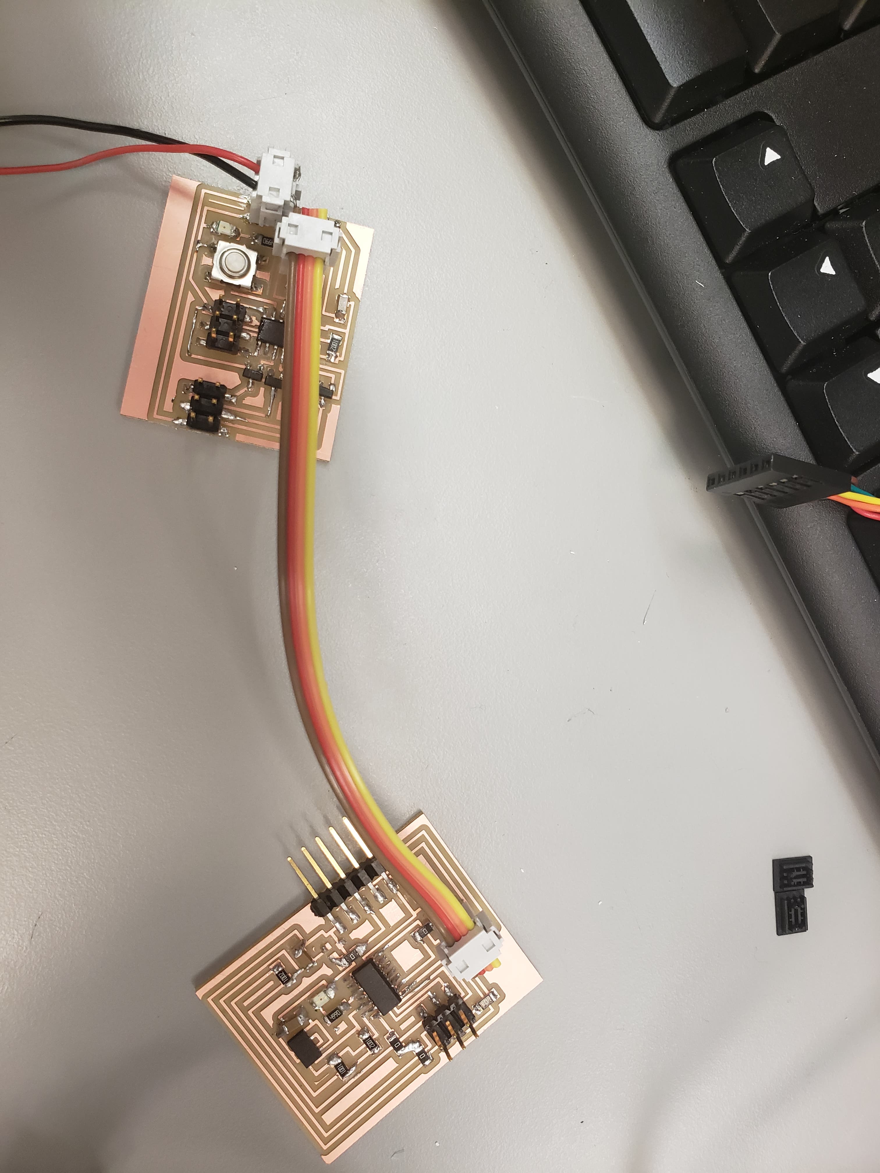
The actual creation of the boards was not bad. At the same time, since I struggled so much making the boards in the past, soldering them this week took no time, and worked on the first try. In order to ensure that the board worked, I tested them alone with previous weeks code. Thankfully, it all worked well!
I came into the coding very hopeful, which turned out to not work out, which isn't shocking given my previous coding abilities. In order to get the boards working with each other, I tried something simple at first of just getting the LEDs on both boards to blink together using the baseline code from the class website. It didn't seem to be working at all.... Again, I couldn't get the python code working (which I never figured out why...) However, it turned out I had mis-aligned the wires when connecting them which was why it didn't work. After fixing that problem, I was able to get my desired code working, where the button controlled the LEDs on both boards and the motor. I struggled to get the LED's shining really brightly, which I think has to do with using 1 battery which cannot provide enough power. For this reason, I'm looking into other methods for powering my final project.
Although I could get the boards working the way I wanted, I figured I'd go ahead and work more to get the accelerometer turning on the motor. After struggling A LOT(!!!!!!), I gave up and asked Ben. It then turned out that my previous code wasn't working properly... It did what I wanted, but wasn't using proper communication. So, Ben helped me out a ton explaining that I had to send values through the put_char function and recieve values using the get_char function. But this still wasn't working... So we took out the oscilliscope! Looking at the voltage coming out of the accelerometer board, we saw that it was in fact sending information. So, we looked at the stepper board. It seemed to be getting gibberish, so we spent a long time thinking about what the issue could be.
Speaking with Jackie, the Architecture TA, she mentioned that one of the problems was that I didn't connect the Tx of one board with the Rx of the other, and vice versa. I mentioned this to Ben and we worked through my wiring to make sure that it was all ok. It turns out that this was part of the issue. I finally understood that the Tx and Rx wording was confusing since sometimes it was in the FTDI point of view and sometimes in the ATTiny point of view. So I figured out that the Tx of the FTDI connects with the ATTiny Tx of the first board (all of this in the point of view of the FTDI), but then I need that to connect with the Tx of the second board (in the point of view of the ATTiny on the second board) or the Rx of the second board (in the point of view of the FTDI). All of that sounds super confusing, but after thinking about it for wayyyyyy too long, I figured it out and got the proper connection.
Using the oscilliscope, we figured out that this still wasn't working. So I went back to my Eagle schematic for the motor board, and noticed that I had inputted the wrong pins for the Tx and Rx. Once I fixed this, the oscilliscope showed that I was getting the value from the accelerometer!!!!!! Since I had struggled so much, I was just sending the number 5 every couple of seconds, and the motor was recieving this and turning on the LED!!!!!!