 Amnahir
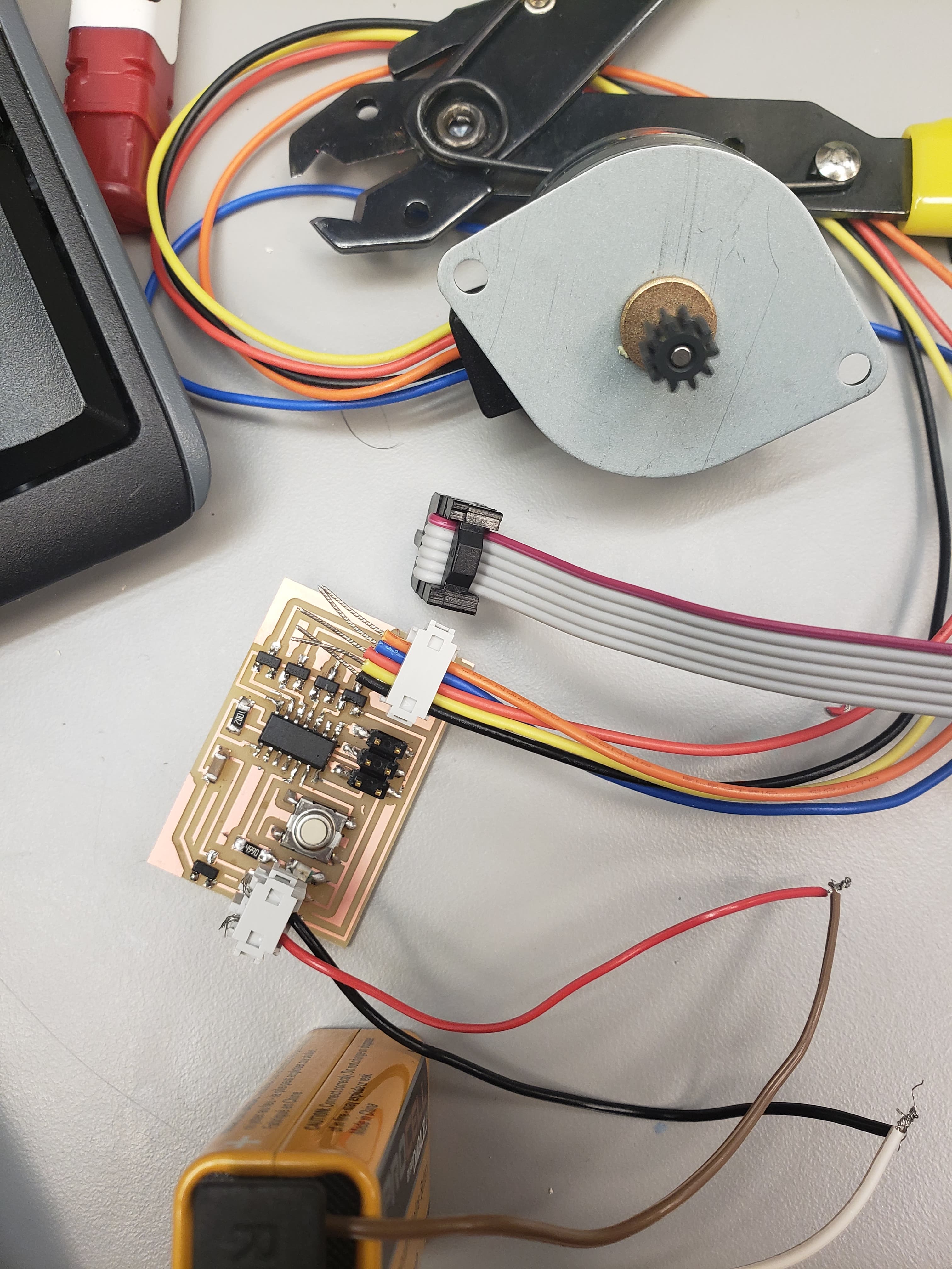
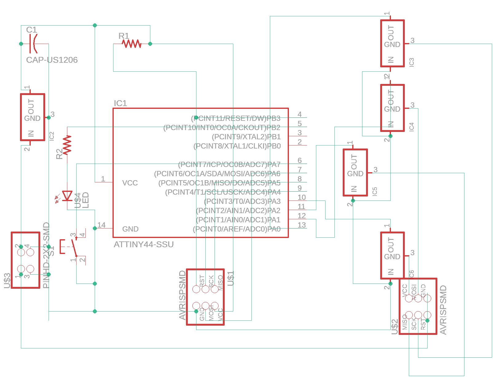
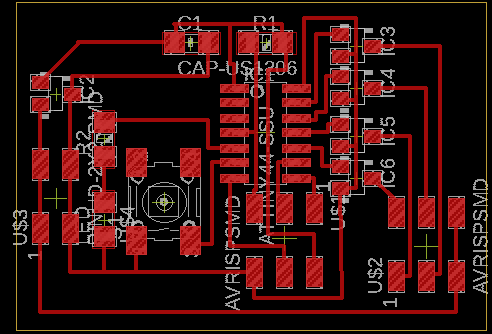
For the 10th week, we had to make a PCB with an output device. I chose a unipolar stepper motor. This is because I was hoping to use this type of motor for my final project. As the motor would be used to lift the bottom of the dress while the user is running. I chose the stepper motor since I thought that it would be stronger than the servo motor, since I had used those in the past. This seemed like it would be a pretty easy week, since I wasn't altering the board on the class website too much. However, it turned out to take sooooooooooo long, sadly. For my first board of the week, I just copied the board on the website. I then altered it by adding a button and LED (the board and schematic shown below). I created all of them on a Roland SRM-20 mill and created the files on Eagle.
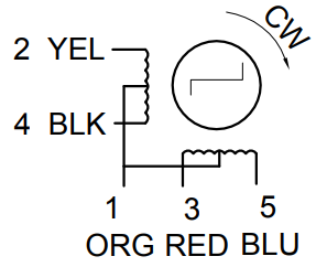
The first board I made was identical to the one made in class (literally identical!!!!). However, it would not work :'(. The motors in lab only had 5 wires coming out of it (black, yellow, red, blue, and orange). This did not match the wires in the video on the class website which had 6 (yellow, orange, brown, black, red, green). So I tried using the data sheet to match which color wire matched which color in the board online. Given the datasheet diagram (shown below), the only thing I was sure of is that the orange wire is VCC, which matches to red and green in the video.
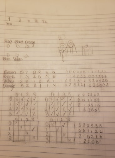
Once I had eliminated orange from an option, I tried using logic to get the final configuration. However, my logic was not working. I then tried changing all of the pin matching in the code. I went through literally every pairing possible (shown below), which took forever to track and go through. But still nothing worked....
So I gave up and found previous students' webpages (click here for the useful one) and got their code and the wire pairings. This allowed me to figure out which pins which wires needed to together, in order to get the right ordering when creating the 6 pin prong. After this, it still didn't work... So I resoldered everything twice and nothing worked.
Finally I came back the next day, and reprinted the board, and did it all again to no avail. Then Zach discovered that the MOSFETs had been mislabeled and I had P-type not N-type. When I finally switched them out, my board worked right away....
Once I finished the first board, the second one worked write away. I quickly combined the code from embedded programming week, and was able to get the button, LED, and motor working correctly!