 Amnahir
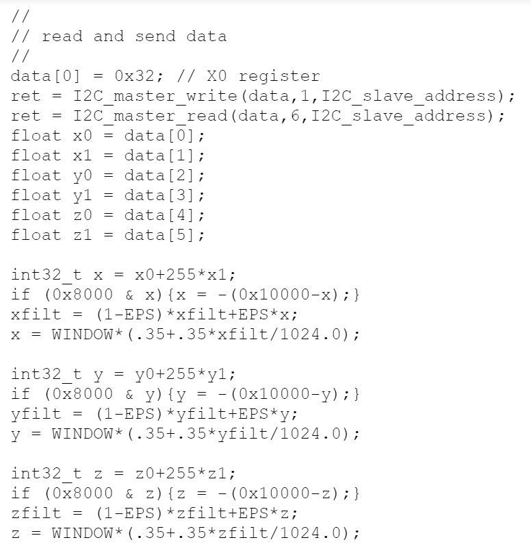
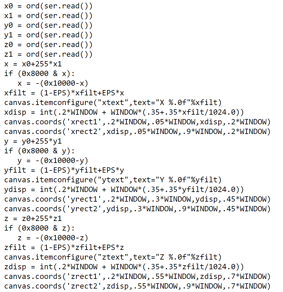
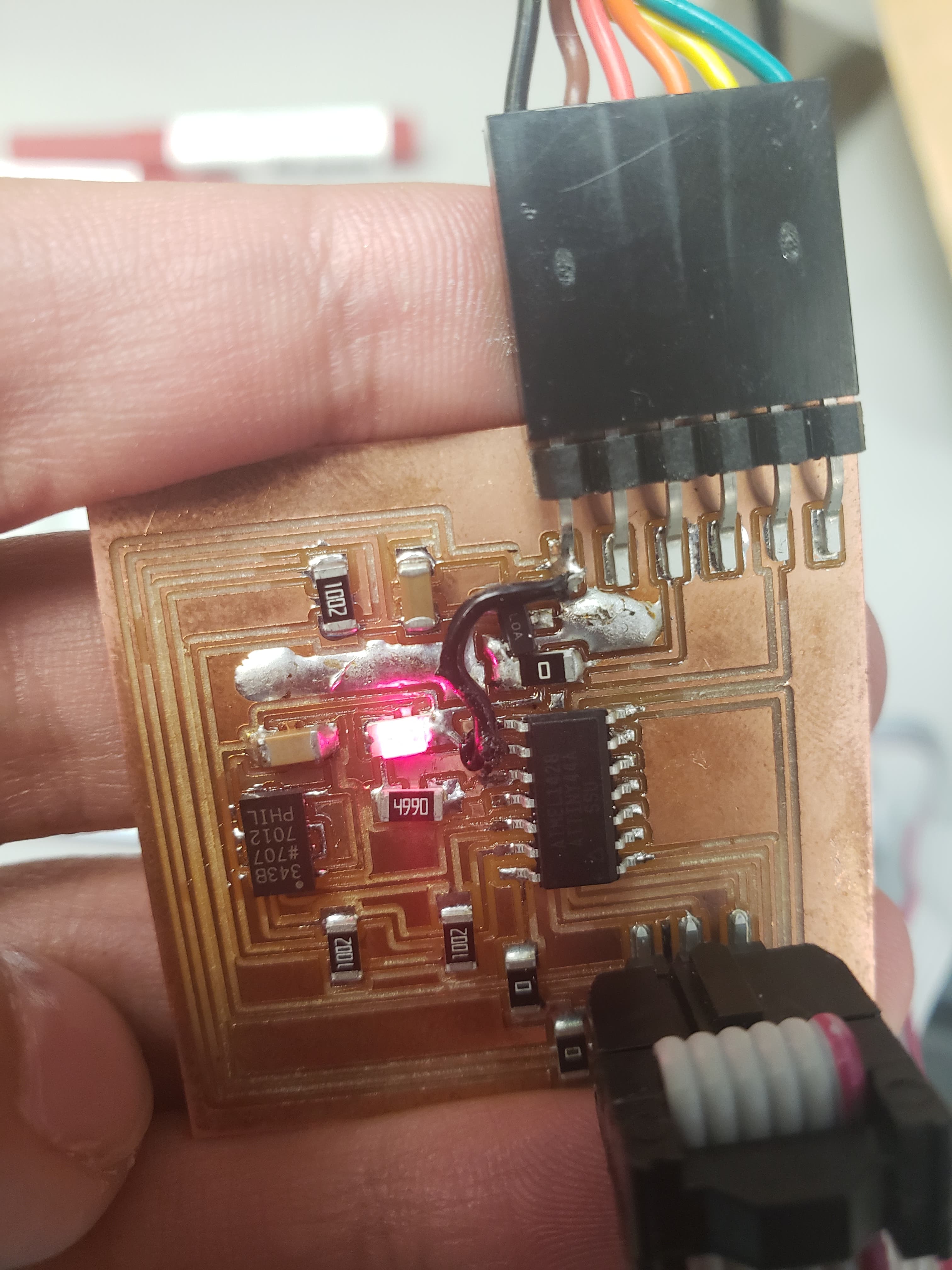
For the ninth week, we had to make a PCB with an input device. I chose the accelerometer, ADXL343. I chose this input component since it was what I was planning on using in my final project, as I want to be able to measure when someone is running versus when they are walking. I had designed the board using Eagle, and was able to mimic the board posted on the class website, but I chose to use an ATTiny 44 instead of a ATTiny 45 (the switch turned out to be super hard). I also added an red LED. The goal was to create a program which would turn on the LED when the acceleration is greater than a threshold.
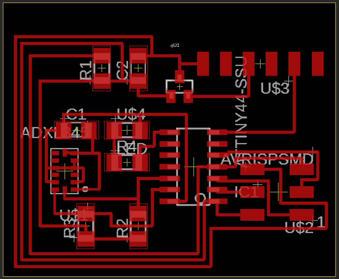
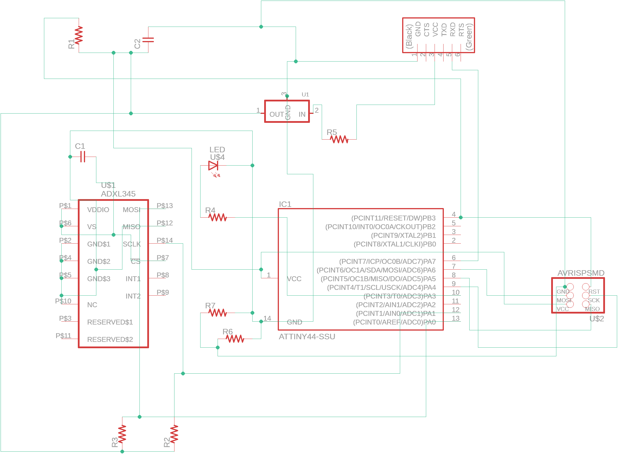
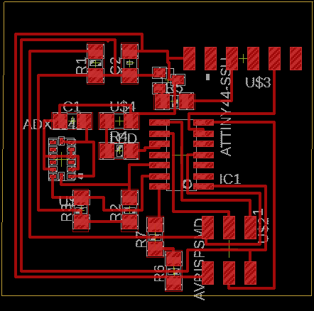
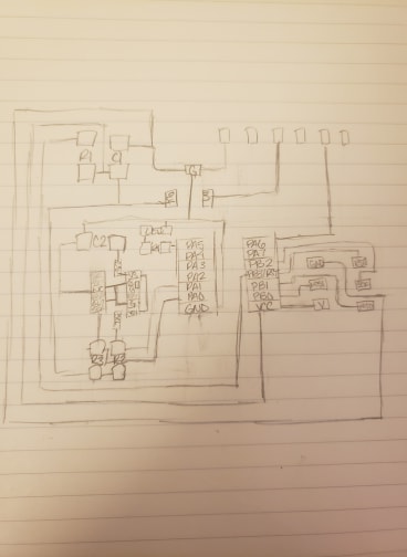
I quickly noticed that I couldn't find the ADXL343 footprint on the fab library that I had downloaded into Ealge. So, I found a footprint online that I downloaded, but it turns out that this was for an ADXL345, which had different names for the pins but the same footprint. Although the layout of the pins matched, the names did not, so I had to do some weird thinking to figure out which pin was which in the schematic. This was done by going back and forth from the board diagram to the schematic to the board on the class website constantly until I figured it out. I also realized very quickly while trying to design the board that it was going to be difficult with all of the different components. This was especially true since the accelerometer had pins going in a variety of directions. After hours and hours of struggling, I decided that I couldn't get the design working on the program. As such, I drew out the diagram and that enabled me to find an efficient way to organize all of the different components.
Once this problem was fixed, I realized that I had to change the footprint of the accelerometer. In addition, the footprint I downloaded had pins of the correct size, but they were too close together for the Roland SRM-20 mill I was going to use. As such, I had to alter them so that they were all smaller. I had to make each pin footprint 32x14 in Eagle so that the mill could separate them. This took a really long time, since I didn't know at the time that you could alter all of the pads at one time, so I did each one separately. I also did this twice, since I wasn't sure it was 32x14 the first time.