 Amnahir
This week we had to make a programmer. Since I wasn't sure what this was, it turns out that the circuit boards we will be making later cannot directly communicate with the computer. So, this programmer will allow us to download code onto the circuit. In order to do this, we had to mill (Using a Roland SRM-20) out the PCB, which is composed of copper and epoxy glass. We used mods to create the cutting path that the mill would follow. After that, we had to solder on all of the different components (I learned that this is called "stuffing" the board). Finally, we had to program the programmer with another programmer.
For the traces in the mill, we used a 1/64" bit endmill. For the outer edges, we used a 1/32" endmill. We were told to be super careful with the 1/64" endmill since they break really easily! We were also told to make sure that the endmill wasn't too far into the holder or too far out, or we would have an unclean cuts on our board.
Directly after learning how to use the mill, 4 of my class mates all decided to stay late and finish milling the boards. It was exciting as we worked together to make sure we followed all of the steps and didn't break anything. Surprisingly, it didn't take that long for us to get the hang of it, and finish milling all 4 of the boards. Afterwards, the soldering was not difficult for me, as I spent all summer soldering mm-scale wearable devices. Although the capacitors in this class are small, this summer it was literally impossible to find a capacitor if it wasn't under the microscope. So I felt well equipped for this step. Although I had used reflowing for the soldering, so using an actual tip pen looking thing turned out to be hard, but in the end I got it.
Sadly the programming was not as easy for me!! :( I was unable to download all of the software I needed (specificall avrdude) because apparently it is super difficult to do on Windows. So after spending a lot of time trying to figure it out, I ended up having to go to the lab computers to program the machine. In the end it worked out, and my board is done!
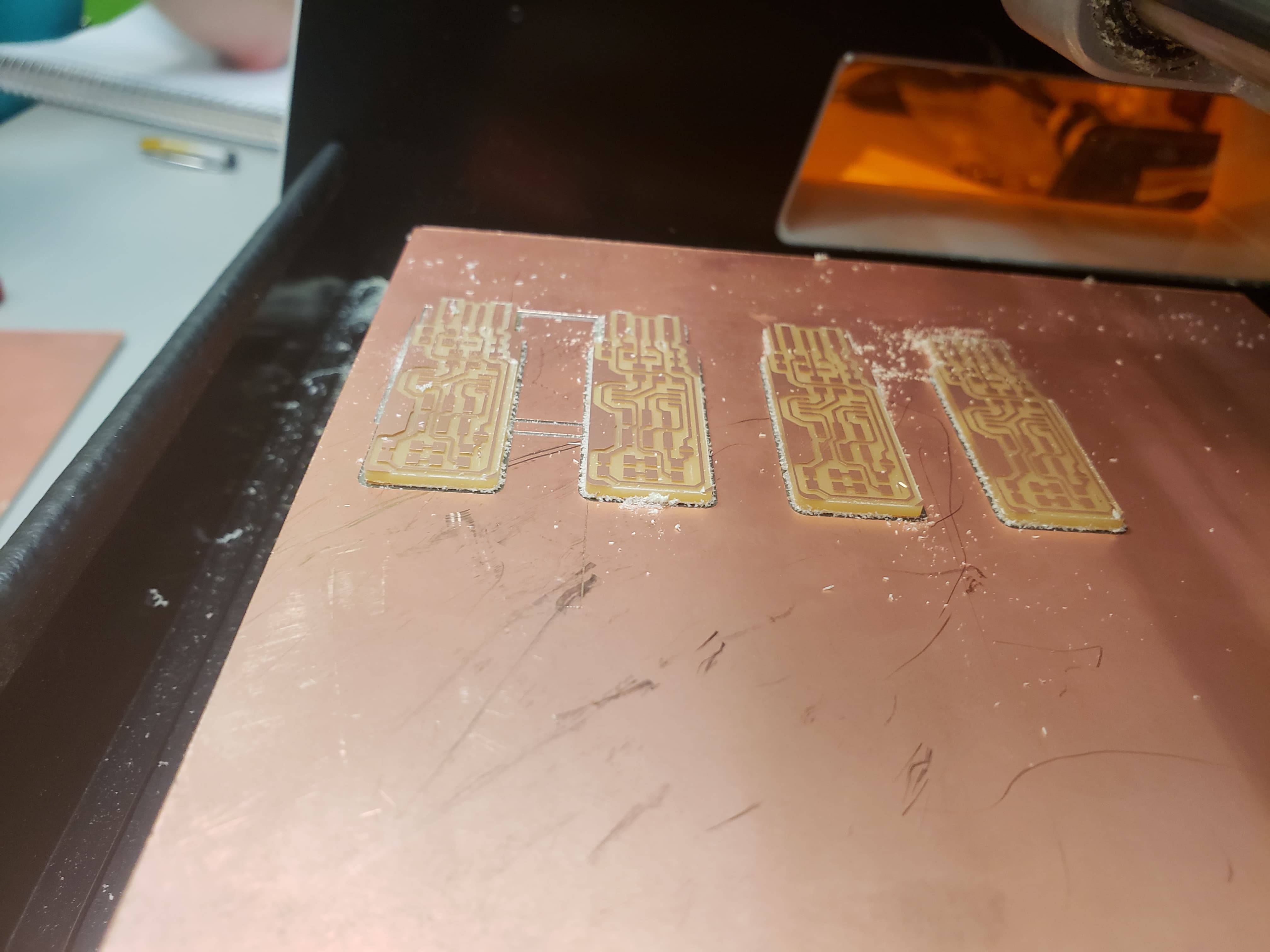
The picture on the left above shows the four boards that we milled and their location, since we did it all from one piece at the same time. We milled them with 25mm in between each space, so that we were sure that they wouldn't interfere with each other. We also vacuumed the board between each piece to ensure that nothing got onto the pick.
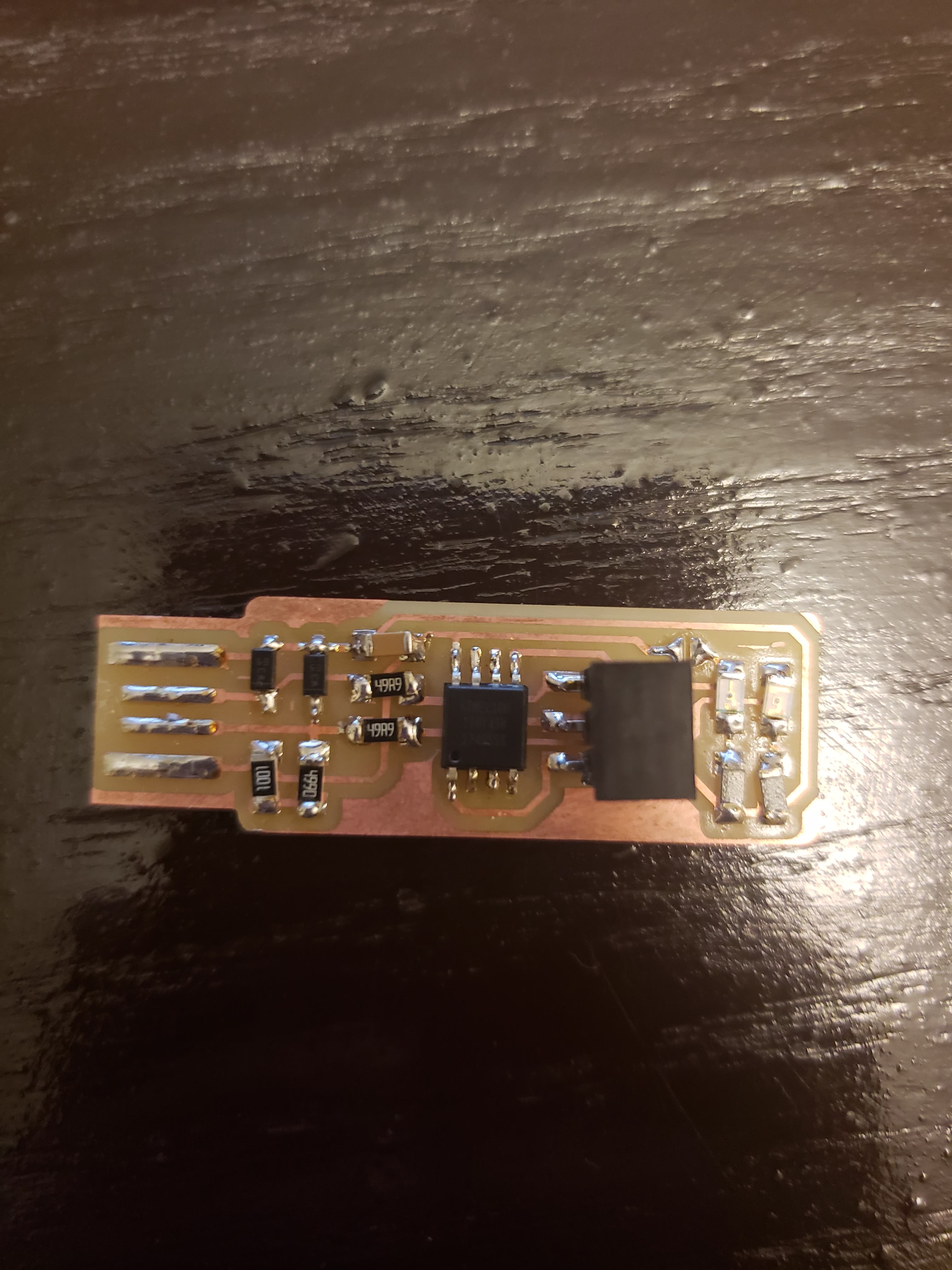
The picture above on the right shows the final board. I still have the cover on the 6 prong connector, to ensure that it does not break while in my backpack. Although the soldering isn't super gorgeous, it works!!