Final Project
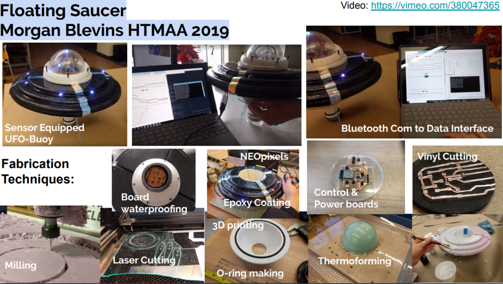
Summary:
I love space! I love the ocean! Space and oceans make a mysterious and exciting combo. More importantly I am interested in my research in creating resilient sensing techniques for investigating extreme environments like these. As an introduction to my work I am intersest in creating a water-tight sensing platform that bridges space and sea. For my final project I built a smart UFO-Buoy, equipt with a waterproof sensor probe, bluetooth communication, and a data streaming interface, while using almost all of the techniques explored in HTMAA.


Project Video:


Addressing the questions about the project:
What does it do?
This buoy collects color and temperature proporties of water and displays the readings of a GUI that the use can toggle a button on to change the color of the Buoy LEDs.

Who's done what beforehand?
Smart buoys have been made my many makers. Here are some examples.
In all my research I haven't found anyone that has made a UFO-shaped buoy! And a buoy + outreach/display device seems to be an uncommon item (at least I couldn't find any.)

What did you design?
  The body (& all 3-d printed components)
  The foam float
  The waterproof sensor board & all electronics
  The clear dome
  Lasercut board mounts and Buoy stand/legs

What materials and components were used?Where did they come from? & How much did they cost?


What parts and systems were made? What processes were used?
The body:
          3D Printing
          Thermoforming
          Milling
          Epoxy Application
          Laser Cutting
Electronis:
          Circuit board Milling
          Vinyl cutting
          LED wiring

What questions were answered?How was it evaluated?
How can I communicate with sensors/buoys remotely? - successful bluetooth communication link!
Can I waterproof sensors and water instruments? - sensors reading underwater!
Can I make an engaging/exciting project to start conversations about alien oceans? - I talked with many people about this at the open house and they seemed excited!

What are the implications?
In my future research I feel enabled to make systems that draw on these techniques. I'll also be able to keep adding fun UI features to this so I can share it at outreach events- both AeroAstro and WHOI based. Additionally I can switch out the sensor puck on the probe for another as long as I make it the same size!
PROCESS
1. Planning
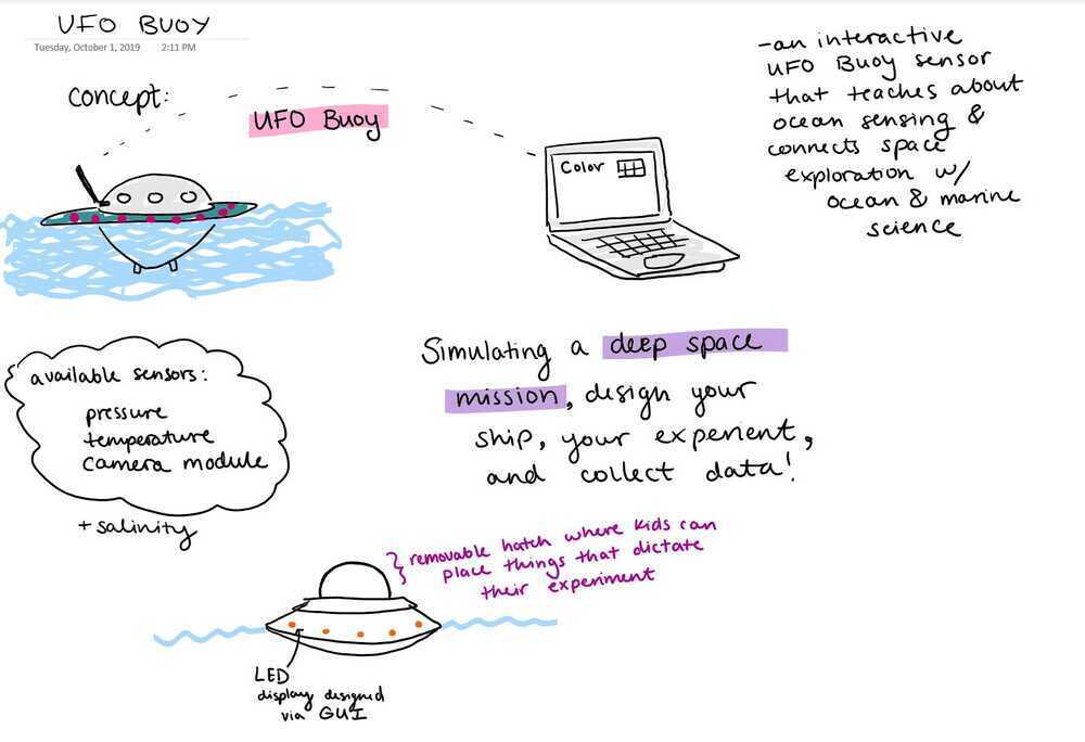
Developing Idea:
I want to make an outreach focused project in which I develop a platform where students can design and conduct alien-ocean themed experiments, centering around the topic of chemical sensing and marine sciene with a space flair.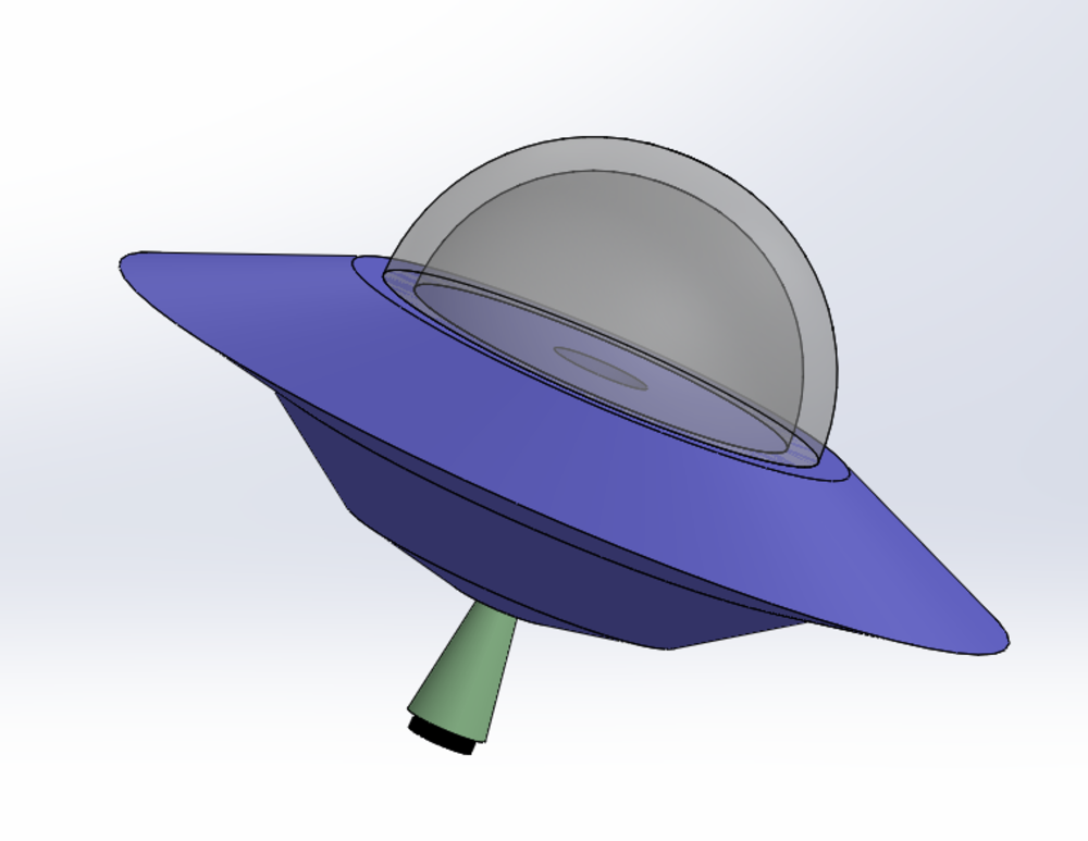
Motivation:
I'm a student in the WHOI-MIT Joint Program. At WHOI I work in the Applied Ocean Physics Engineering department and my research has a heavy focus on instrumentation that can be deloyed and used in marine environments. If I want to be able to make depolyable instruments/devices I need to make robust, waterproof, highly reliable, and reusable designs. I want to use what I learn in this class to make my own device that meets this requirement for working in the ocean while also making it affordable and modular. This idea feels very in the spirit of Fab-Labs because it promotes afforability and access in the world of ocean engineering but also lets me find an opportunity to make something to enage kids with ocean/space sceince!Design Requirements:
1. A suite of sensors for pressure, salinity & temperature and a PCB board that runs thems. 2. A UFO shaped buoy housing that protects the sensors' board. 3. Wifi & bluetooth communcation links from the instrument that interact with a GUI that live plots the data to an interactive MATLAB GUI. 4. A wireless charging battery pack. 5. An array of lights that react to and visualize the data that the sensors are reading. 6. An openable upper "hatch" where students could place items that inpact what types of experiments are being done OR what the ufo looks like (could utilize inductive coils inside little placeable objects?)Initial Bill of Materials:
CAD:
Initial Idea...More flushed out idea including the sensor housing (make it look like the little spooky abduction light):
Initial Electronics Design:
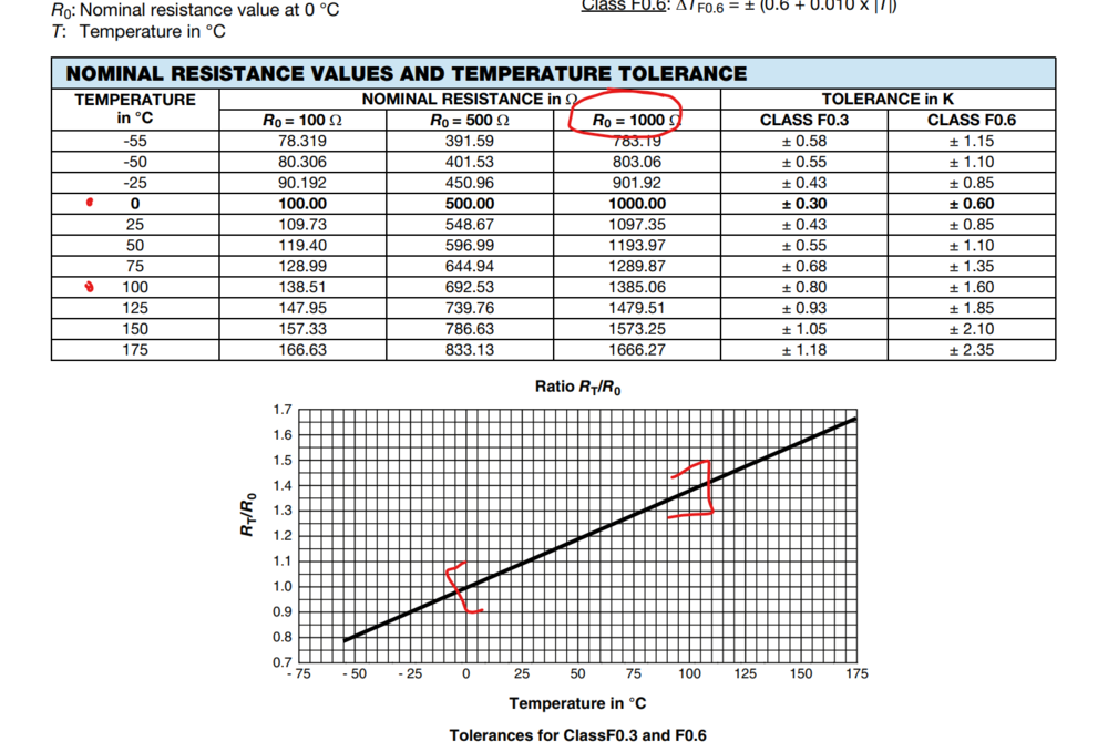
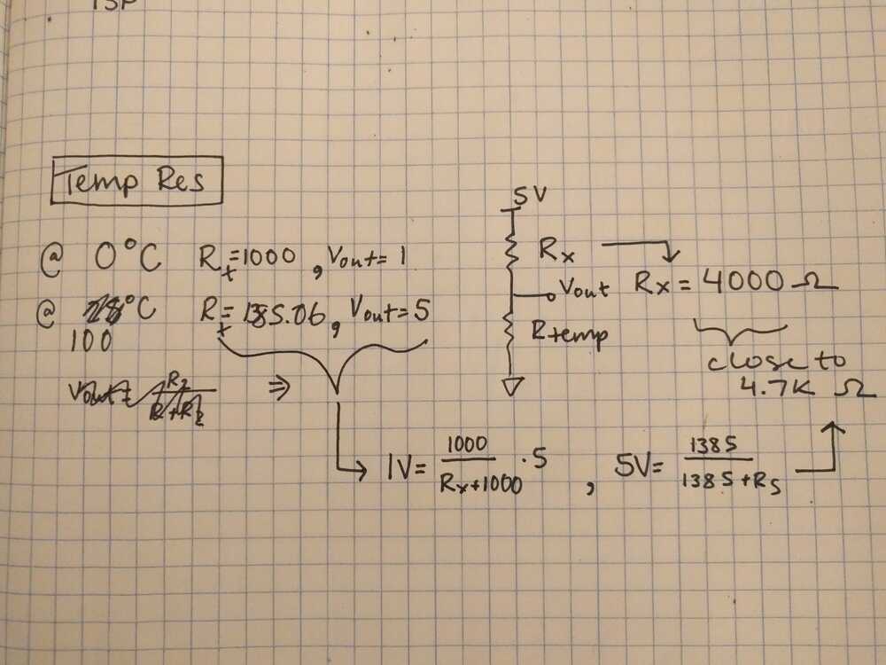
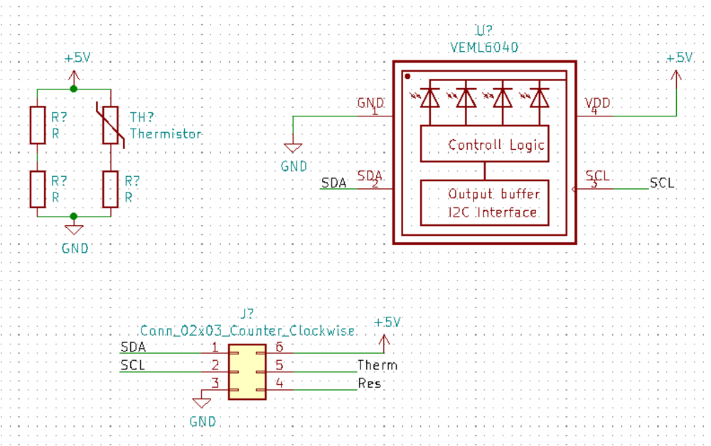
My project will use tempurature, pressure, and as many others sensors as I can get my hands on.The HTMAA provided temp. sensor works in a simple volage divider:
Planning for the semester...
I met with Diego for a check in on my final project and through our meeting took the following step in planning out the systems of my final project:Input Devices Week 10/30/19 to 11/6/19:
Key Deliverables this week: 1. Build the main board for my project with the key sensors. Buttons Allows user to toggle display options Temp Sensor Water measurement Color sensor Water measurment Hall Effect Sensor (Magnetic Sensor) Allows user to place object inside UFO to change a setting Add turbidity sensor//hydrocarbon sensor??!! link to article commerical trubidity sensor digikey products: http://www.vishay.com/docs/82843/tssp940.pdf https://www.digikey.com/product-detail/en/osram-opto-semiconductors-inc/SFH-4243-Z/475-2866-1-ND/2207283 2. Waterproof the sensors for the watermeasurments 3. Build the UFO "light" sensor holder.Output Devices Week 11/7/19 to 11/13/19:
1. Add all the output devices to my UFO board from prior week LED array React to sensor readings Temp: Blue to Red to visualize temperature Color: Replicate the color being read by sensor Have a series of LED lights mounted on a milled rings that fits inside the clear housing of the UFO React to user button press Blink or do some sequence when button is pressed Speaker Alien tune in response to button press or other input 2. 3D print UFO Base 3. Mold the transparent domeNetworking & Communcation Week 11/14/19 to 11/20/19:
1. Bluetooth communcation to laptop GUI 2. GUI for the UFO2. Final Project Systems
Inputs:
0. ESP32 "mother" board For my hardware, I chose the ESP32 for the chip to control the input and output devices and talk to my computer. I talk about this chip a bit in my input devices week as well as my networking week. My final ESP32 board was this: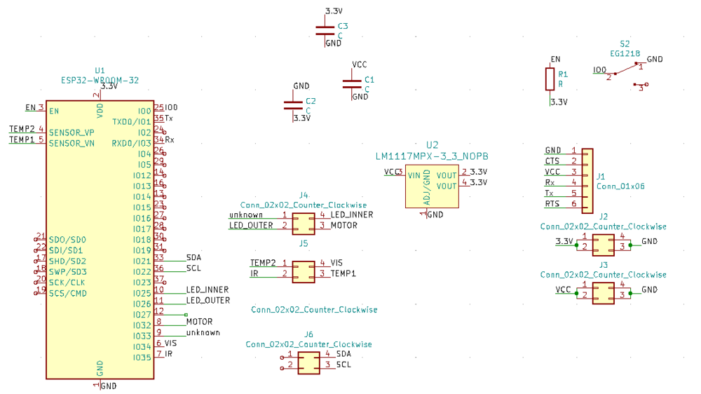
It has input pins for the IR, Visible light, and temperature sensors, as well as pins at the SCL and SDA pins for I2C communicaion to the VEMl6040. It includes a regulator to take the battery power input down to 3.3V to power the chips and sensors. It also has bypass capacitors and a pull up resistor for the reset button. There also incluses a slide switch to the enable pin and a button to the reset pin. The enable pin must be switched in order for you to program the board.
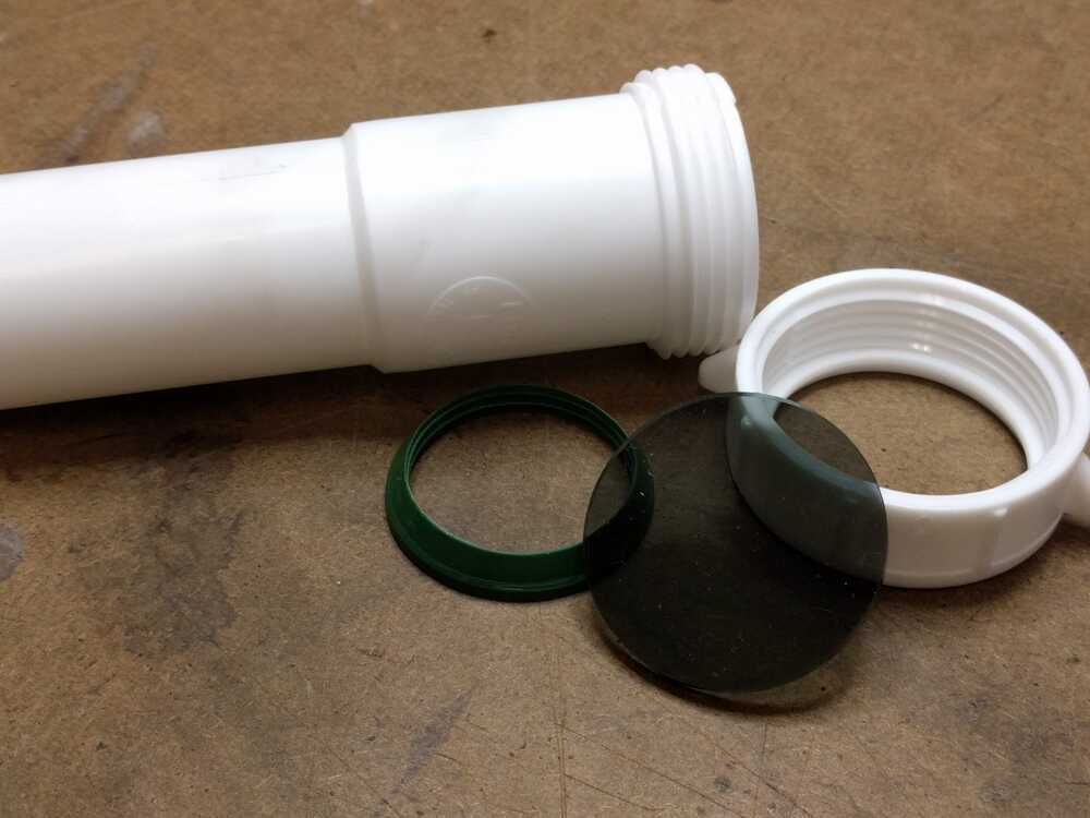
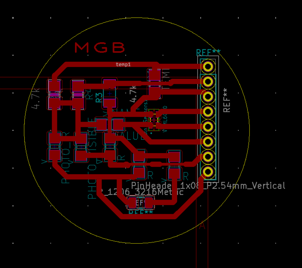
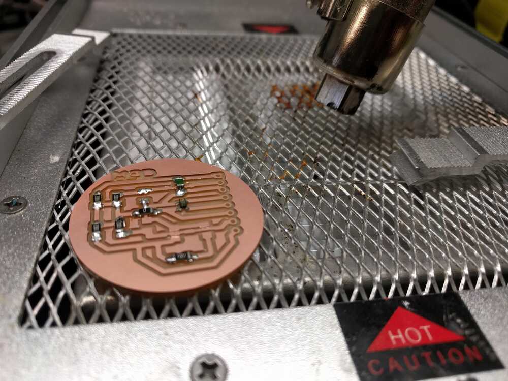
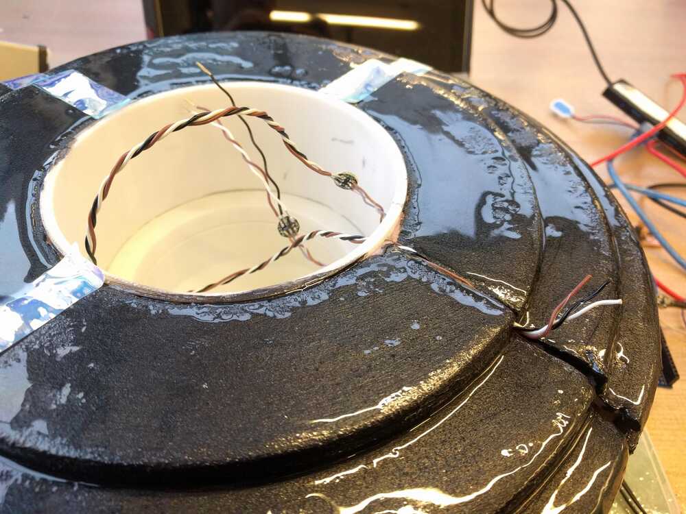
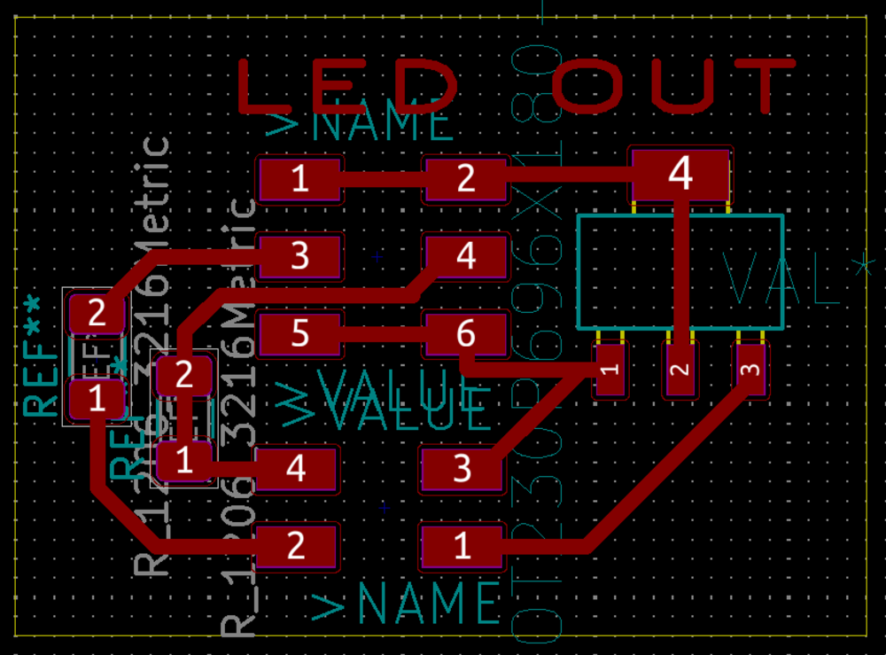
1. Water sensing The idea behind the sensor board is that it will be populated with a bunch of water sensors and could be either (a) lowered into bowls of water if the buoy is on display at an event of (b) be secured into the bottom of the buoy so it could be set out in the water to collect measurements During Inputs week I built a board with a hall, temp, and-- sensors. This board was successful in some ways but had mysterious shorts that I couldn't debug in hardware of software. For my final board I plan to continue with the thermistor sensor config. but incorporate my own turbidity, visible light, and optical color sensors. As parts of wildcard week I designed and built a vinyl cut version of my final waterproof sensor board. I loved this board (and also thought it was beautiful) but it unfortunately did not have very solid connections and when I tested my sensors they only worked after I heavily resoldered the traces. At first I was happy with that, but after laying epoxy the sensors starting giving wonky readings again, so a more solid board was needed :(.
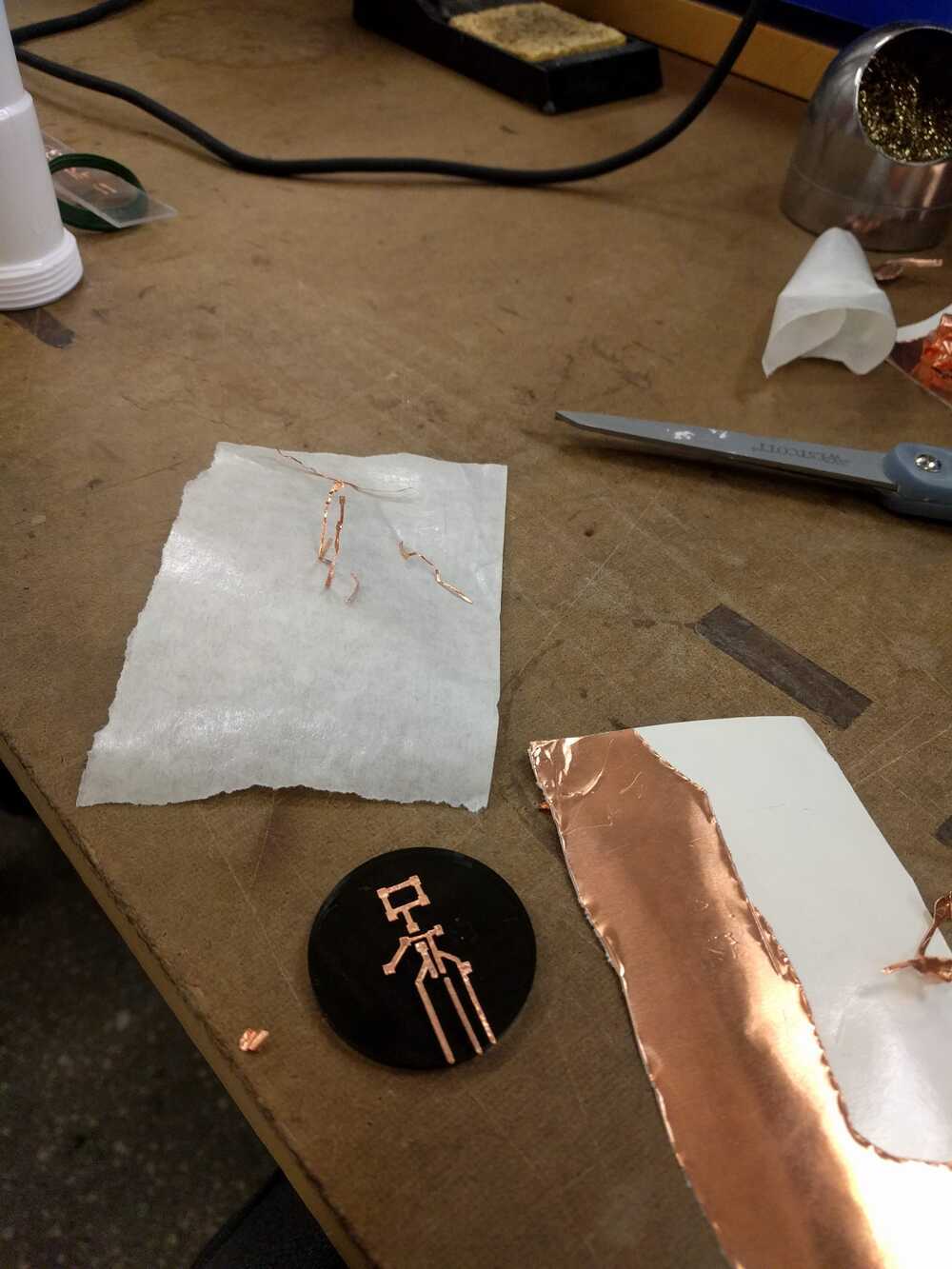
I designed this board with through holes to replace it, it’s pretty much the same except I added an IR LED so that I could have a turbidity measurement.
I needed to waterproof my board so I tested which epoxys were best for passing light. I panted layers of epoxy options on a metal sheet and when they were dry I saw how my sensor performed with them.
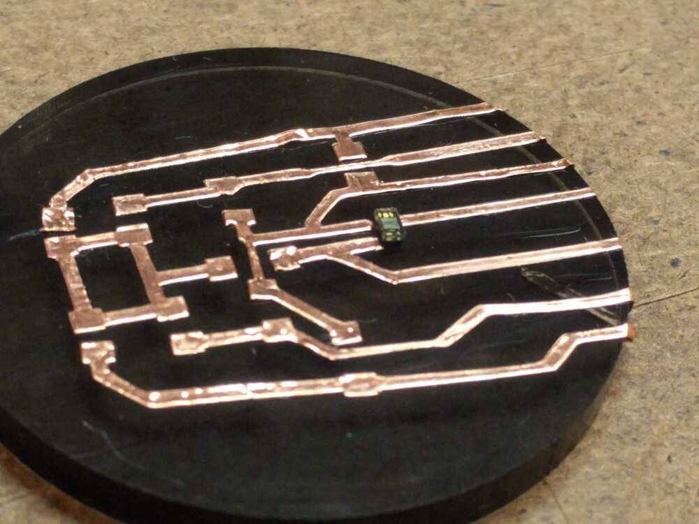
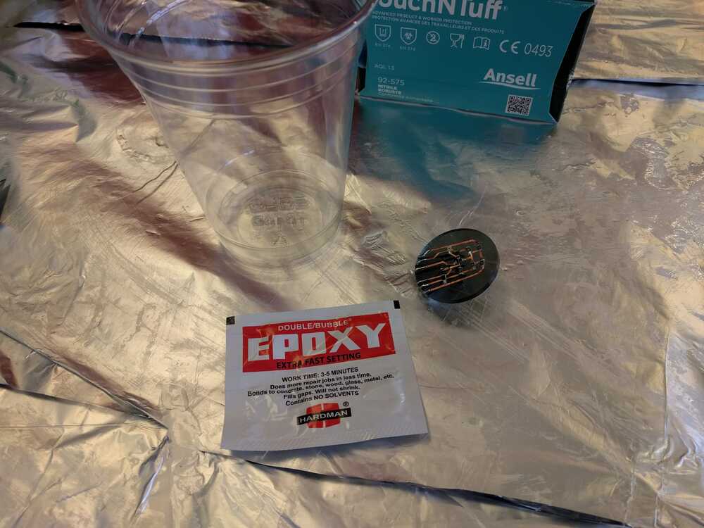
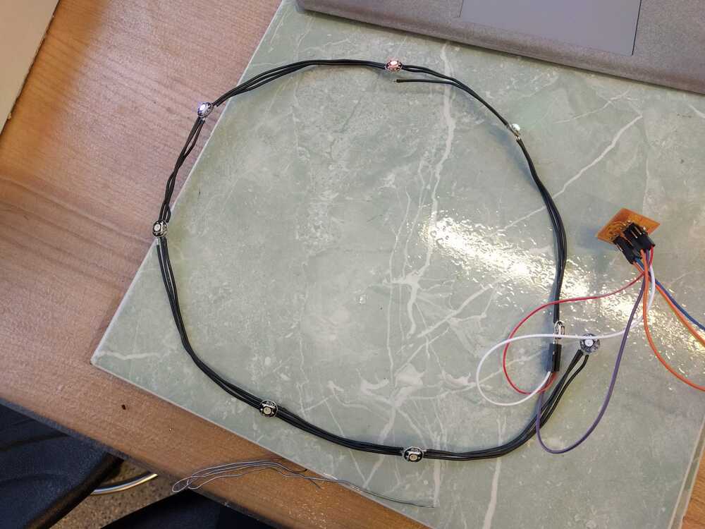
Right before expoy-ing my board I retested the board to ensure everything (cause you can’t really undo this!). The color LED worked but the radings on all the other pins were high. This was really strange. I took a multimeter and measured the voltages on the sensor board and those were fine… FIGURED IT OUT^! When using WIFI you can’t use the ADC2 on the esp32 and all of my analog input pins that I was using were using ADC2… YIKES. Now I have to make a new board with input pins that use ADC 1, aka GPIOs 32 - 39. SIGH. I rebuilt the board with the new GPIO pin assignments and after populating it, it worked :). I waterproofed the board with two coats of 5-minute epoxy. Following this is soldered wire to the leads on the opposite side of the board and covered those is shrink wrap. Next I soldered female headers onto the ends of those wires so they could be plugged into the ESP32 board.
I finally tested that these sensors were in fact waterproog
I used Arduino to program my ESP32, built from a collection of example programs and my own additions. Here is my final code used for the project:
//set up bluetooth-------------- #include "BluetoothSerial.h" BluetoothSerial SerialBT; //------------------------------ //set up LEDS------------------ #include2. Probe button: I want the UFO to be interactive both via a GUI and physically. I’d like to have a button or potentially hall sensor that allows the user to actuate the sensor probe. --Update-- I ended up not actuating the probe so did not incorpoate a button to lower it.#ifdef __AVR__ #include // Required for 16 MHz Adafruit Trinket #endif // Which pin on the Arduino is connected to the NeoPixels? // On a Trinket or Gemma we suggest changing this to 1: #define LED_PIN 26 // How many NeoPixels are attached to the Arduino? #define LED_COUNT 12 // NeoPixel brightness, 0 (min) to 255 (max) #define BRIGHTNESS 20 // Declare our NeoPixel strip object: Adafruit_NeoPixel strip(LED_COUNT, LED_PIN, NEO_RGB + NEO_KHZ800); // Argument 1 = Number of pixels in NeoPixel strip // Argument 2 = Arduino pin number (most are valid) // Argument 3 = Pixel type flags, add together as needed: // NEO_KHZ800 800 KHz bitstream (most NeoPixel products w/WS2812 LEDs) // NEO_KHZ400 400 KHz (classic 'v1' (not v2) FLORA pixels, WS2811 drivers) // NEO_GRB Pixels are wired for GRB bitstream (most NeoPixel products) // NEO_RGB Pixels are wired for RGB bitstream (v1 FLORA pixels, not v2) // NEO_RGBW Pixels are wired for RGBW bitstream (NeoPixel RGBW products) //------------------------------ //set up sensor stuff----------- #include "Wire.h" #include "veml6040.h" VEML6040 RGBWSensor; //Define INPUTS----------------- int ir_pin = 35; // select the input pin for the potentiometer int vis_pin = 34; // select the input pin for the potentiometer int temp2_pin = 36; // select the input pin for the potentiometer int temp1_pin = 39; // select the input pin for the potentiometer int ir_val = 0; // variable to store the value coming from the sensor int vis_val = 0; // variable to store the value coming from the sensor int temp2_val = 0; // variable to store the value coming from the sensor int temp1_val = 0; // variable to store the value coming from the sensor int temp= 0; int red =1; int green= 1; int white= 1; int blue= 1; int cct=1; int al=1; int r=0; int g=0; int b=0; //------------------------------ //Interface controls------------ //------------------------------ void setup() { //Set pins-------------------- pinMode(LED_PIN, OUTPUT); pinMode(ir_pin, INPUT); pinMode(vis_pin, INPUT); pinMode(temp2_pin, INPUT); pinMode(temp1_pin, INPUT); //---------------------------- // Set up USB Serial port----- Serial.begin(115200); //---------------------------- //Set up Bluetooth Serial port SerialBT.begin("hello.ESP32-WROOM.SPP"); printf("\nBluetooth ready for pairing and serial communication\n\n"); //---------------------------- //Set up VEML6040------------- Wire.begin(); if(!RGBWSensor.begin()) { Serial.println("ERROR: couldn't detect the sensor"); while(1){} } /* * init RGBW sensor with: * - 320ms integration time * - auto mode * - color sensor enable */ RGBWSensor.setConfiguration(VEML6040_IT_320MS + VEML6040_AF_AUTO + VEML6040_SD_ENABLE); delay(1500); Serial.println("Vishay VEML6040 RGBW color sensor auto mode example"); Serial.println("CCT: Correlated color temperature in \260K"); Serial.println("AL: Ambient light in lux"); delay(1500); //---------------------------- //Set up LEDs----------------- // This is for Trinket 5V 16MHz, you can remove these three lines if you are not using a Trinket #if defined (__AVR_ATtiny85__) if (F_CPU == 16000000) clock_prescale_set(clock_div_1); #endif // End of trinket special code strip.begin(); // INITIALIZE NeoPixel strip object (REQUIRED) strip.show(); // Turn OFF all pixels ASAP strip.setBrightness(50); // Set BRIGHTNESS to about 1/5 (max = 255) //---------------------------- } void loop() { // if (SerialBT.available() > 0 ) { // read the incoming byte: char c = SerialBT.read(); if (c=='r'){ // say what you got: //SerialBT.print("I received: "); //SerialBT.println(incoming); colorWipe(strip.Color(255, 182, 193), 50); colorWipe(strip.Color(255, 105, 180), 50); colorWipe(strip.Color(255, 20, 147), 50); } } //USB Serial output Serial.print("RED: "); red=RGBWSensor.getRed(); Serial.print(red); Serial.print(" GREEN: "); green=RGBWSensor.getGreen(); Serial.print(green); Serial.print(" BLUE: "); blue= RGBWSensor.getBlue(); Serial.print(blue); Serial.print(" WHITE: "); white=RGBWSensor.getWhite(); Serial.print(white); Serial.print(" CCT: "); cct=RGBWSensor.getCCT(); Serial.print(cct); Serial.print(" AL: "); al=RGBWSensor.getAmbientLight(); Serial.println(al); // read the value from the sensor: ir_val = analogRead(ir_pin); vis_val = analogRead(vis_pin); temp2_val = analogRead(temp2_pin); temp1_val = analogRead(temp1_pin); temp = temp2_val-temp1_val; // turn the ledPin on Serial.print("IR: "); Serial.print(ir_val); Serial.print(", Vis:"); Serial.print(vis_val); Serial.print(", T: "); Serial.println(temp); //Bluetooth Outputs //values from VEM6040 SerialBT.print(red); SerialBT.print(","); SerialBT.print(green); SerialBT.print(","); SerialBT.print(blue); SerialBT.print(","); SerialBT.print(white); SerialBT.print(","); SerialBT.print(cct); SerialBT.print(","); SerialBT.print(al); SerialBT.print(","); //values from read the value from the sensor: SerialBT.print(ir_val); SerialBT.print(","); SerialBT.print(vis_val); SerialBT.print(","); SerialBT.println(temp); //Calculate color of object/water: r= (int) 255*(red)/(red+blue+green); g= (int) 255*(green)/(red+blue+green); b= (int) 255- (r+g); //SerialBT.print(r); //SerialBT.print(","); //SerialBT.print(g); //SerialBT.print(","); //SerialBT.println(b); //colorWipe(strip.Color(r, g, b), 50); // color of object is wiped along UFO //colorWipe(strip.Color(255, 0, 0), 50); // Red colorWipe(strip.Color(123,104,238), 20); // Green colorWipe(strip.Color(123,104,238), 20); // Green colorWipe(strip.Color(123,104,238), 20); // Green colorWipe(strip.Color(135,206,235), 20); // Blue colorWipe(strip.Color(135,206,235), 20); // Blue colorWipe(strip.Color(135,206,235), 20); // Blue //colorWipe(strip.Color(0, 0, 0, 255), 50); // White RGBW } // Fill the dots one after the other with a color void colorWipe(uint32_t c, uint8_t wait) { for(uint16_t i=0; i< strip.numPixels(); i++) { strip.setPixelColor(i, c); strip.show(); delay(wait); } } void rainbow(uint8_t wait) { uint16_t i, j; for(j=0; j< 256; j++) { for(i=0; i< strip.numPixels(); i++) { strip.setPixelColor(i, Wheel((i+j) & 255)); } strip.show(); delay(wait); } } // Slightly different, this makes the rainbow equally distributed throughout void rainbowCycle(uint8_t wait) { uint16_t i, j; for(j=0; j< 256*5; j++) { // 5 cycles of all colors on wheel for(i=0; i< strip.numPixels(); i++) { strip.setPixelColor(i, Wheel(((i * 256 / strip.numPixels()) + j) & 255)); } strip.show(); delay(wait); } } //Theatre-style crawling lights. void theaterChase(uint32_t c, uint8_t wait) { for (int j=0; j< 10; j++) { //do 10 cycles of chasing for (int q=0; q < 3; q++) { for (uint16_t i=0; i < strip.numPixels(); i=i+3) { strip.setPixelColor(i+q, c); //turn every third pixel on } strip.show(); delay(wait); for (uint16_t i=0; i < strip.numPixels(); i=i+3) { strip.setPixelColor(i+q, 0); //turn every third pixel off } } } } //Theatre-style crawling lights with rainbow effect void theaterChaseRainbow(uint8_t wait) { for (int j=0; j < 256; j++) { // cycle all 256 colors in the wheel for (int q=0; q < 3; q++) { for (uint16_t i=0; i < strip.numPixels(); i=i+3) { strip.setPixelColor(i+q, Wheel( (i+j) % 255)); //turn every third pixel on } strip.show(); delay(wait); for (uint16_t i=0; i < strip.numPixels(); i=i+3) { strip.setPixelColor(i+q, 0); //turn every third pixel off } } } } void color(uint8_t wait) { for (int j=0; j < 256; j++) { // cycle all 256 colors in the wheel for (int q=0; q < 3; q++) { for (uint16_t i=0; i < strip.numPixels(); i=i+3) { strip.setPixelColor(i+q, Wheel( (i+j) % 255)); //turn every third pixel on } strip.show(); delay(wait); for (uint16_t i=0; i < strip.numPixels(); i=i+3) { strip.setPixelColor(i+q, 0); //turn every third pixel off } } } } // Input a value 0 to 255 to get a color value. // The colours are a transition r - g - b - back to r. uint32_t Wheel(byte WheelPos) { WheelPos = 255 - WheelPos; if(WheelPos < 85) { return strip.Color(255 - WheelPos * 3, 0, WheelPos * 3); } if(WheelPos < 170) { WheelPos -= 85; return strip.Color(0, WheelPos * 3, 255 - WheelPos * 3); } WheelPos -= 170; return strip.Color(WheelPos * 3, 255 - WheelPos * 3, 0); } Outputs:
1. WS2812B Addressable LEDs These light will go around the foam exterior of the body. I used these WS2812B Addressable 5050 Smart RGB LED Pixel lights from amazon that other students purchases a group order of:These lights are wonderful! They have extensive libraries and documentation available. I soldered a long chain of them together and glued them to the body of the UFO. In my main code for the project I add lines to control their pattern at the beginning, during data collection, and via a user’s input on my interface.
I designed a simple board to provide 5V (via a ZLDO regulator), GND, and the signal from the ESP32 board I was using.
To run these I used the Arduino Neopixel library! In my first test running and arduino example only the first two worked- the 5V pin came unsoldered when I was moving it, these things are really tough to work with! These things take a lot of power so in this video you see me providing 5V to the LEDS directly from a spare arduino. In my final set up I will need two batteries. 2. Probe Motion I want to making UFO-light (aka sensor probe) move up and down with a step motor! In response to a remote input the ufo light will lower into the water. This process is all outlined in my outputs week page. For outputs week I created a step motor board that turned a motor on and off with the press of a button. ---Update--- After all that work on the stepper motor I decided to isntead used a servo motor for easer control. I designed a mount, rack, and pinion to support the motor and actuate the sensor probe. For our machine week our team used a rack and pinion to grab with the claw. I designed my own rack and pinion in solidworks using the design tools feature. I printed these and the parts actually fit the sensor probe really well! I inserted a rack and pinion and made sure that their design parameters were equivalent. Next I dimensions them to match the up and down actuation I expected to want from the probe shaft. I added a probe holder to the rack and designed a servo-motor mount based on the design that had worked for our Machine week motor.
I designed a motor board very similar to Neil's and milled it and hooked it up to the motor. I programmed it to move up and down (not yet driven by an input device): The servo-motor board is very simple. The only inputs externally are power, ground, and the user’s signal that they’d like the motor to actuate.
I ended up not integrating this (1) because I did not incorporate support for holding the motor and its casing inside the buoy body and (2) because I wanted to have a waterproof project by the end of this and this was going to be a riskier item in the body. 3. Acrylic Lamp inside the dome My inspiration! I designed an acrylic globe cut out using a free vector file of a terrain plot for vecteezy.com. I found a beautiful scrap piece of acrylic in the Arch shop and the peice after calibrating the cut and score values. I designed a charlieplexed LED to put below the acrylic cut out: I ended up not using this but still really enjoyed it!
Networking:
I would like to use networking to control the LEDs in the UFO and to also get data from the sensors and allow me to visualize it with my interface. During networking week I used the ESP32 to send data from my input week sensor to my computer. The ESP32 will be the “mother chip” of my project. This is where all of my sensor inputs will go and where the controls to the outputs will be sent from. I built my final ESP32 board and used Neil’s bluetooth to bluetooth serial example. Initially I had a defective ESP32 and it gave me garbled outputs, but after replacing it on the same board I was able to get the ESP32 to act like a bluetooth device and get recognized by my computer. My next step was to output all my sensor variables via the bluetooth serial port. First I used the arduino example library to connect my esp32 to my computer serial port.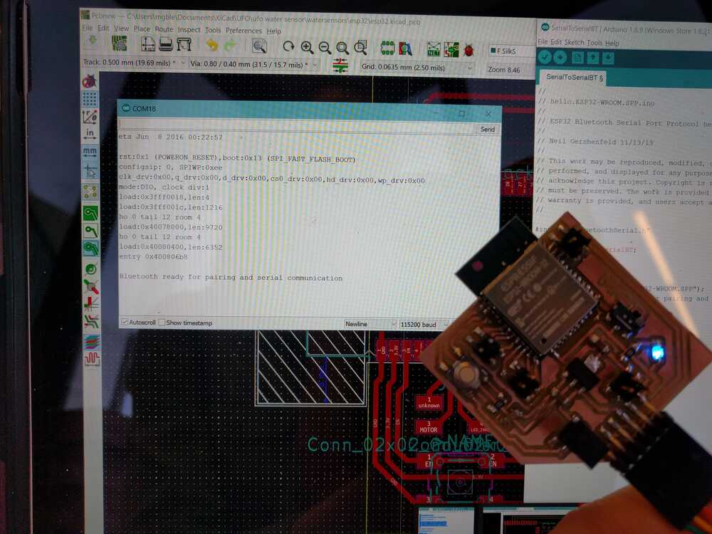
Next I modified my SerialCom.cs file in Unity to recognize this serial bluetooth COM port and to parse the string of data- I seperated each data output with a comma and simply split the string at each comma via value.Split(‘,’). I confirmed that all my sensor values could be sent to unity and printed separately to the console. Though I first implemented this in unity, I ended up switching to javascript for reading from the bluetooth serial port. My final javascript for talking to my ESP32 via bluetooth:
var express = require('express'); var app = express(); var server = app.listen(4000, () => { //Start the server, listening on port 4000. console.log("Listening to requests on port 4000..."); }) var io = require('socket.io')(server); //Bind socket.io to our express server. app.use(express.static('public')); //Send index.html page on GET / const SerialPort = require('serialport'); const Readline = SerialPort.parsers.Readline; const port = new SerialPort('COM19', {baudRate: 115200}); //Connect serial port to port COM3. Because my Arduino Board is connected on port COM3. See yours on Arduino IDE -> Tools -> Port const parser = port.pipe(new Readline({delimiter: '\r\n'})); //Read the line only when new line comes. parser.on('data', (temp) => { //Read data console.log(temp); var today = new Date(); io.sockets.emit('temp', {date: today.getDate()+"-"+today.getMonth()+1+"-"+today.getFullYear(), time: (today.getHours())+":"+(today.getMinutes()), temp:temp}); //emit the datd i.e. {date, time, temp} to all the connected clients. }); io.on('connection', (socket) => { socket.on('color', function(data) { console.log(data); port.write(data); }) console.log("Someone connected."); //show a log as a new client connects. })This code successfully links my sensor readings to my interface on my computer.Interfacing:
Based on interfacing week, I first tried using Unity to build my UI. This can communicate via serial to my board and through bluetooth. I successfully got my bluetooth data talking to unity but this program just felt too bulky for what I wanted to achieve. I really liked the three.js examples I saw so I went down that route instead. My process for building my interface for my sensor readings is outlined in my interface week page. My final interface:My interface giving live read outs from my buoy:
UFO Body:
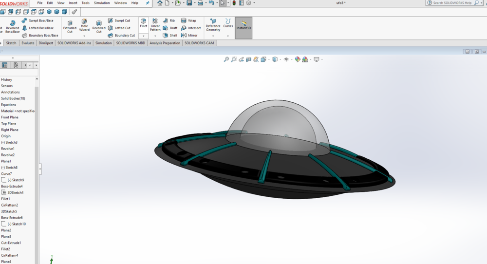
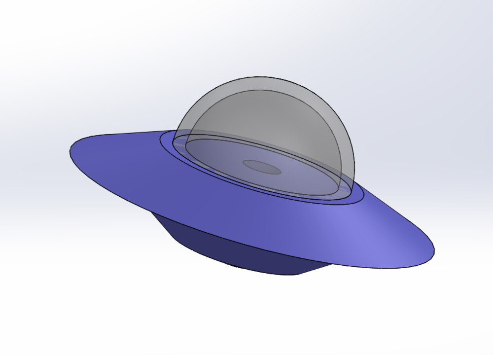
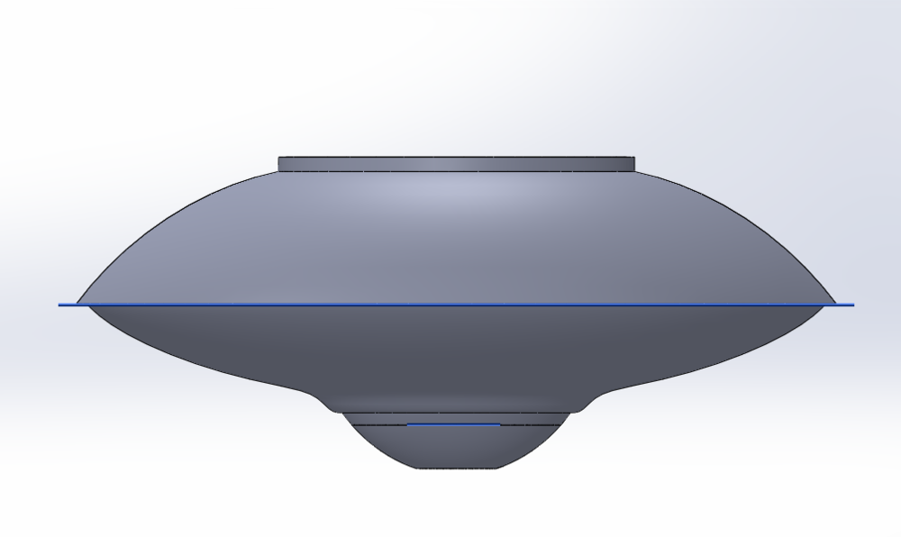
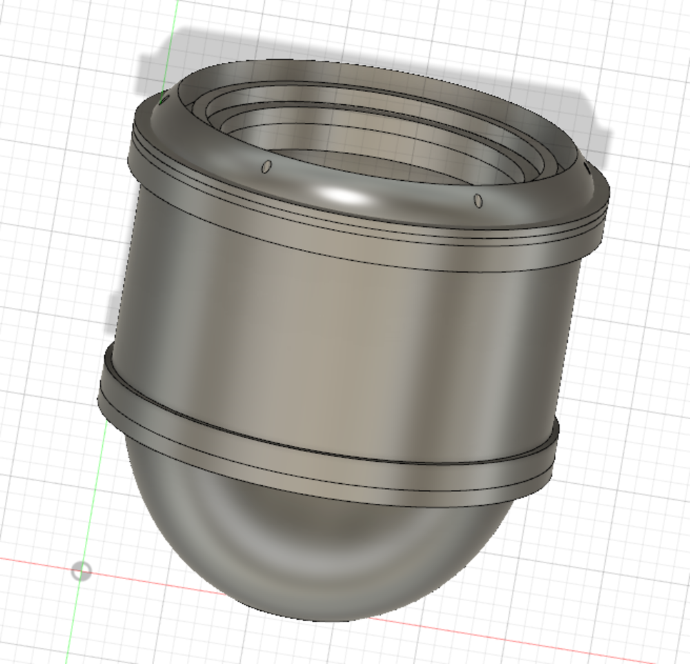
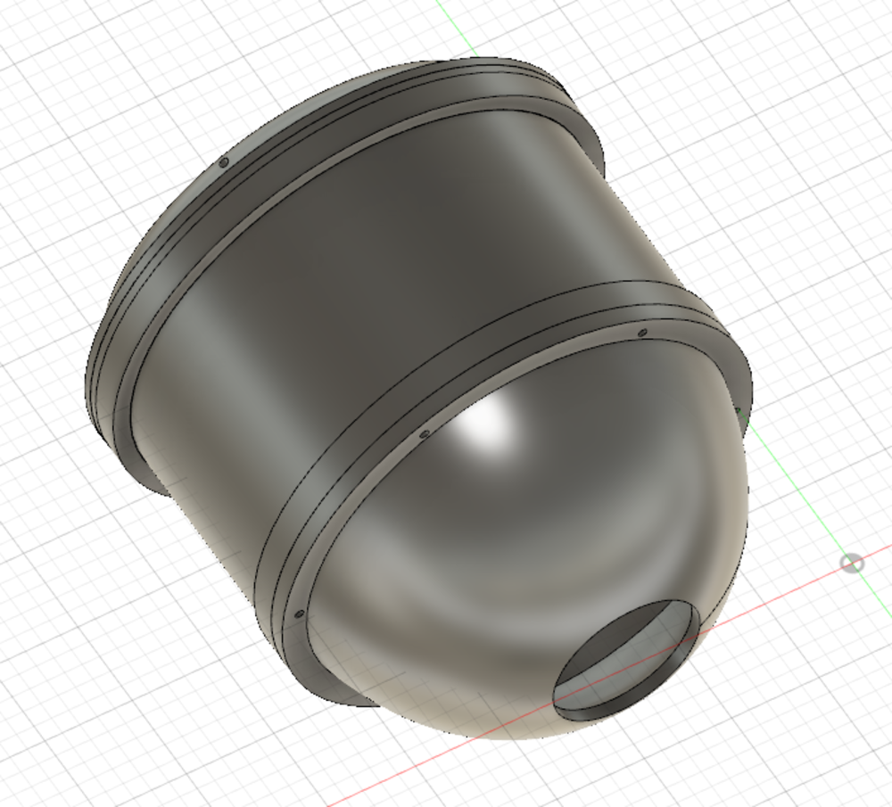
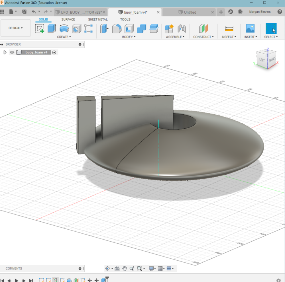
1. 3D printed body: I iterated through MANY designs of the UFO body…I ended up returning to Fusion and regretted ever leaving. I LOVE how easy it is to distinguish different bodies when you are creating sketches off of existing bodies. Here is my final design (note that I decided to have the ufo sloping body portion be foam):
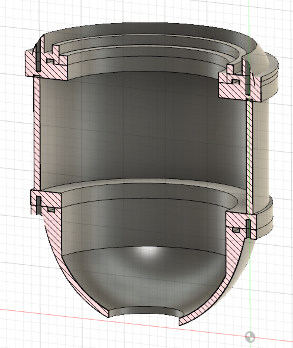
I designed the buoy to be configured in modular pieces, so that I could have a better time 3D printing it and could also get practice designing O-ring slots. The body has a bottom, with a hole for the sensor probe, a middle section to house the probe and any other things, and a top section that supports the clear dome. 3D printing process: I did 4 printed total, (1) the base (2) the middle section (3) the section to join the middle and top (4) the top section 2. Thermoformed top: Making the clear dome for the top of the buoy was a perfect chance to learn and use thermoforming. This is explained in detail in my wildcard week page.
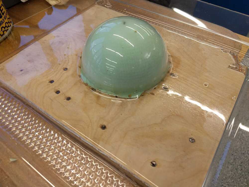
I epoxy-ed the dome into a 3D printed home.
3. Milled out foam body To provide buoyancy to my buoy I’ll be using the purple foam as the UFO body. I CAD'ed up the foam body that I wanted, but when using the shop bot I realized that this milling job would take hours. So I set the setp size to be really large and instead embraced the more stepped look.
Foam Process: 1. Mill out foam body top and bottom
2. Cut off excess body
.jpg)
3. (Unfortunately) cut the peices into 4 4. Sand
5. Glue together with gorilla glue
6. Epoxy to the 3d printed buoy body
7. Coat with Mod Podge
.jpg)
8. Paint with two laers of acrylic paint
.jpg)
9. Add tape decals
10. Coat in super-sap CLR epoxy.
2. Making the rubber O-rings I purchased stock o-ring material from amazon. A. Measure the inner diameter of the groove
B. Measure the o-ring diameter
C. The the two diameters and multiply by 3.14. This is your desired o-ring length.
D. Cut the o-ring material at the calculated length
E. Ensure the length looks good!
F. Use superglue to glue the ends together (I only have epoxy but would recommend superglue)
Overview of assembly:
.jpg)
.jpg)
.jpg)
.jpg)
.jpg)
.jpg)
.jpg)
.jpg)
.jpg)