Week 3: Electronics Fabrication
This week we are to deliver a fabricated & functional AVR ISP board programmer!
TLDR:
I made an AVR ISP programmer/board programmer with the FabTinyStar, according to the tutorial on Brian's page.
Work Process:
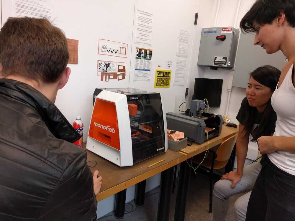
To begin this week of learning electronics frabication I got an orientation of using the PCB endmill.
Setting up PCB mill:
- 1. Select a copper plated board to mill your trace onto (we used the peices proved in the archlab, mostly scap from other projects)
- 2. Coat the bottom in one even layer of double stick tape and attached it to the sacrificial layer in the mill area
- 3. Next use a ruler to measure the (x,y) position of the spot where I wanted to mill my board. Set this point as the origin. NOTE! Choose a spot that wastes the least amount of board material!
- 4. Place the 1/64" diameter end mill in the set screws.
- 5. Send the end mill to the origin and loosen the set screws and gently lower the endmill until it's touching the surface, then retighten the set screws.
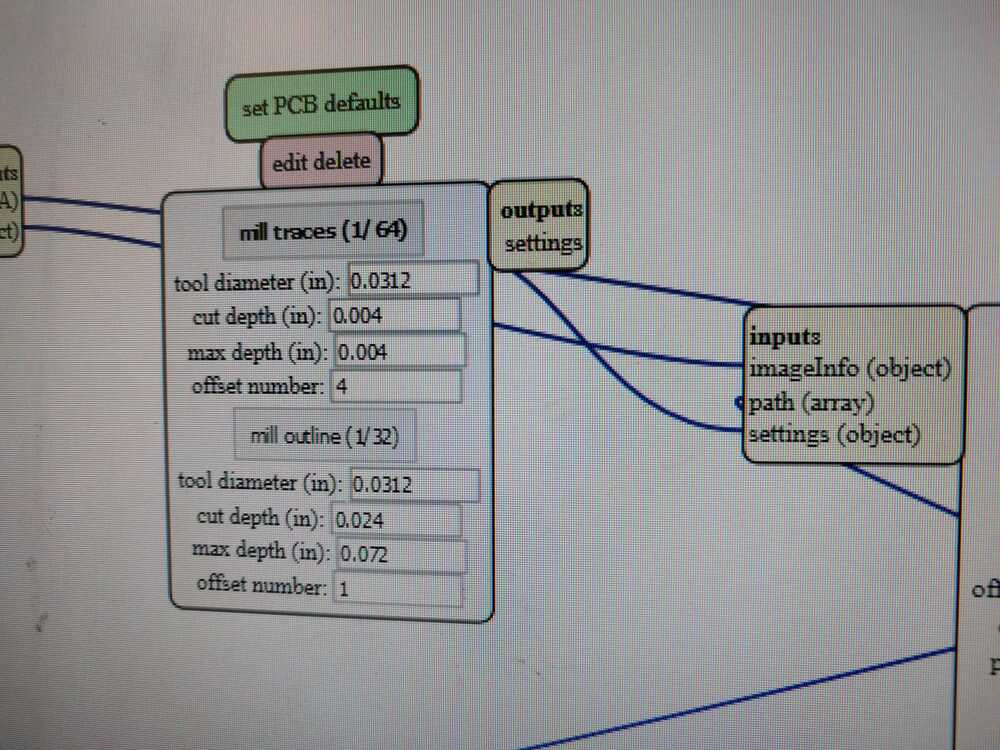
- 6. Upload your .PNG file to Neil's mod and select load traces, ensuring that the settings are for the end mill size you'e using (default 1/64")
- 7. Click "calculate", ensure again that you are at your desired origin, and sent the file to the mill.
- 8. After your traces are milled into the board send the end mill to "home" and replace the endmill bit with the 1/32".
- 9. Send to origin, zero in the z-direction on the board again, and upload your outline file to the mill, this time selecting mill "---".
- 10. Calculate and send to the mill.
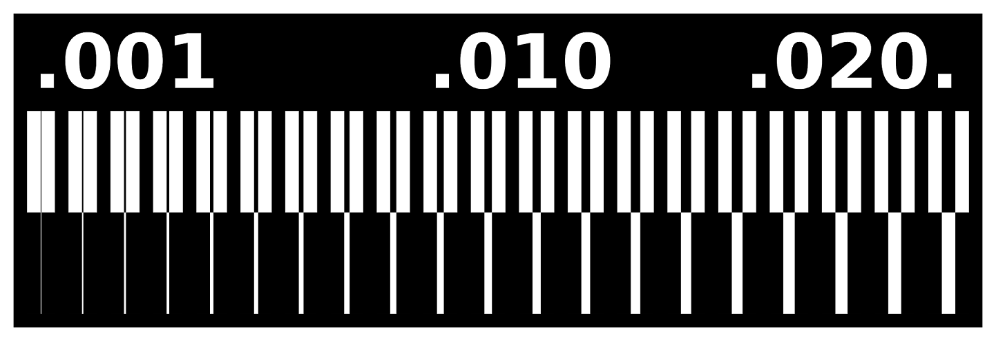
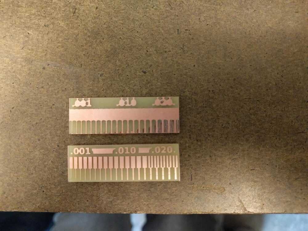
After getting an overview from the TAs, some teammates and I characterized the capabilities of the 1/32" and 1/64" endmills. To do this we printed the linetest PNG file below. This line test will show how small of lines differnt sized endmills are capable of milling.
Here are the PNG files that show the traces and the cut out linetest (the images link to the files).

We followed the procedure I outlined above to first print this file with 1/32" traces.
This resulted in a very innacurate cut, which makes sense as the traces we were attempting were much smaller than the tip.
Next we milled the test board with a 1/64" tip. This resulted in a significantly finer print. This testing & practice definitely conveyed the importance of of using the smallest tip possible when making delicate traces. We also observed that taping the board down carefully and evenly was important, it seemed like on the 1/32" attempt we may have had the tape unevenly hold the board down and it made the depth of cut uneven through out.
Now that I was trained in running the PCB mill, I milled the programmer board.
Here are the PNG files that show the traces and the cut out of the board (the images link to the files).
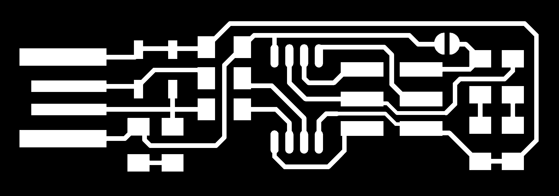

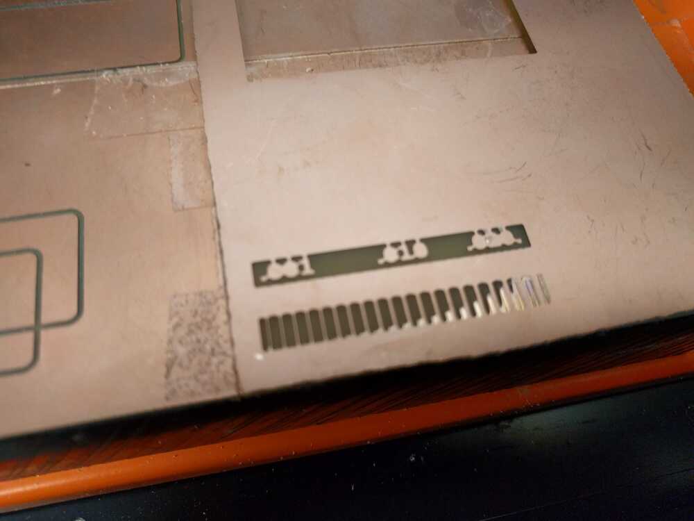
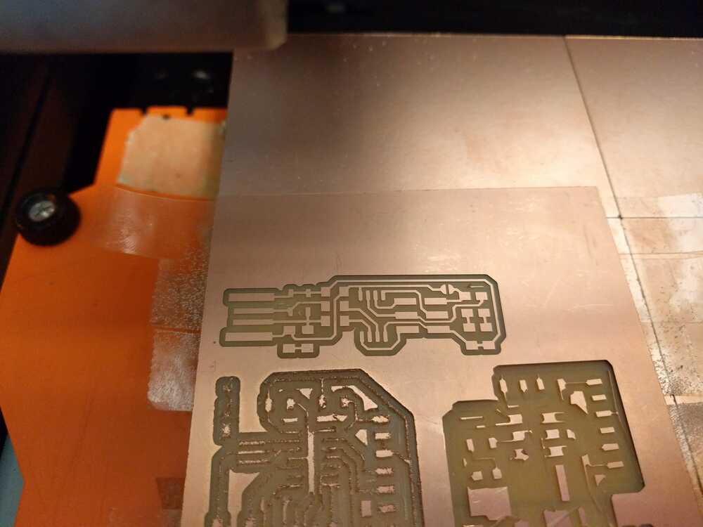
I followed the same procedure I outlined up above! This image shows the board after milling the traces (note how I tried to place it as close as I could to the existing cuts on the board to sae material):
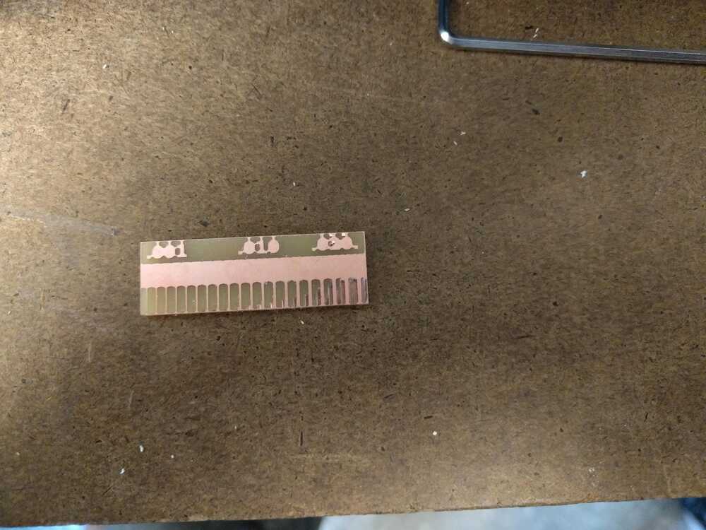
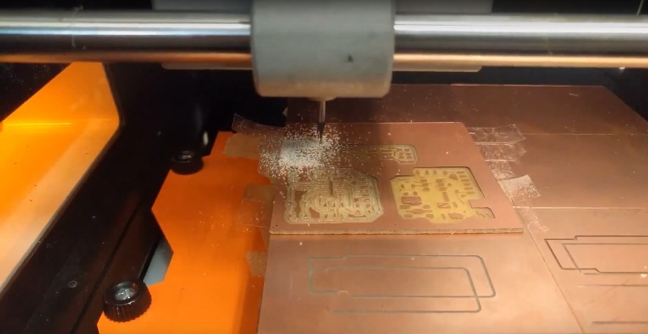
After printing the traces I cut the outline.
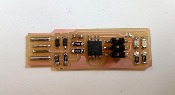
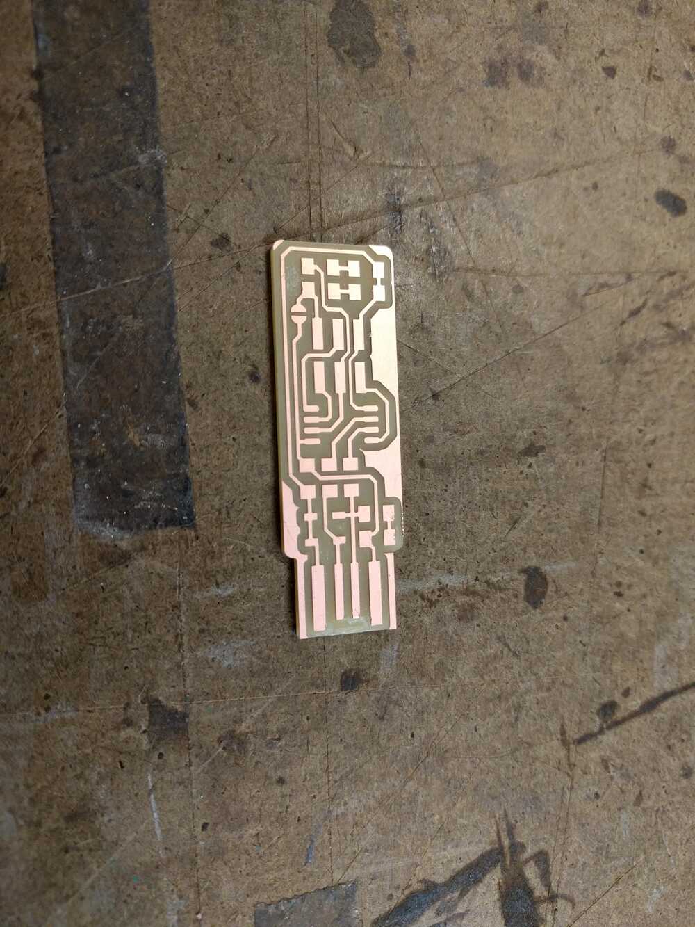
After the board was all milled I scraped off an extra copper coating left on the board until it looked like this:.
Now it was time to solder the components on the board! I followed the layout given on Brain's tutorial:

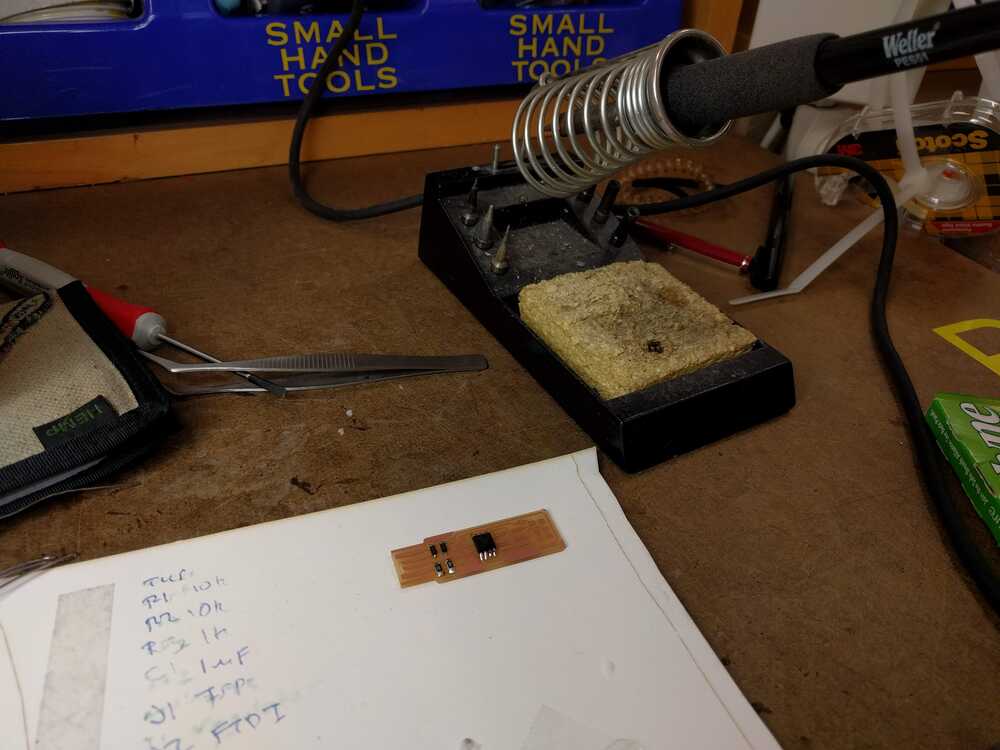
I'm experienced in soldering surface components but I had some big lessons learned from this: (1) tape your board down on a peice of paper so it can be stable but at the same time you can swivel and adjust its position when needed (2) use the giant lens and turn on its giant light! (3) use tweezers to pick up and place your components (4) strategize your soldering order so that things dont get in your way (5) be patient
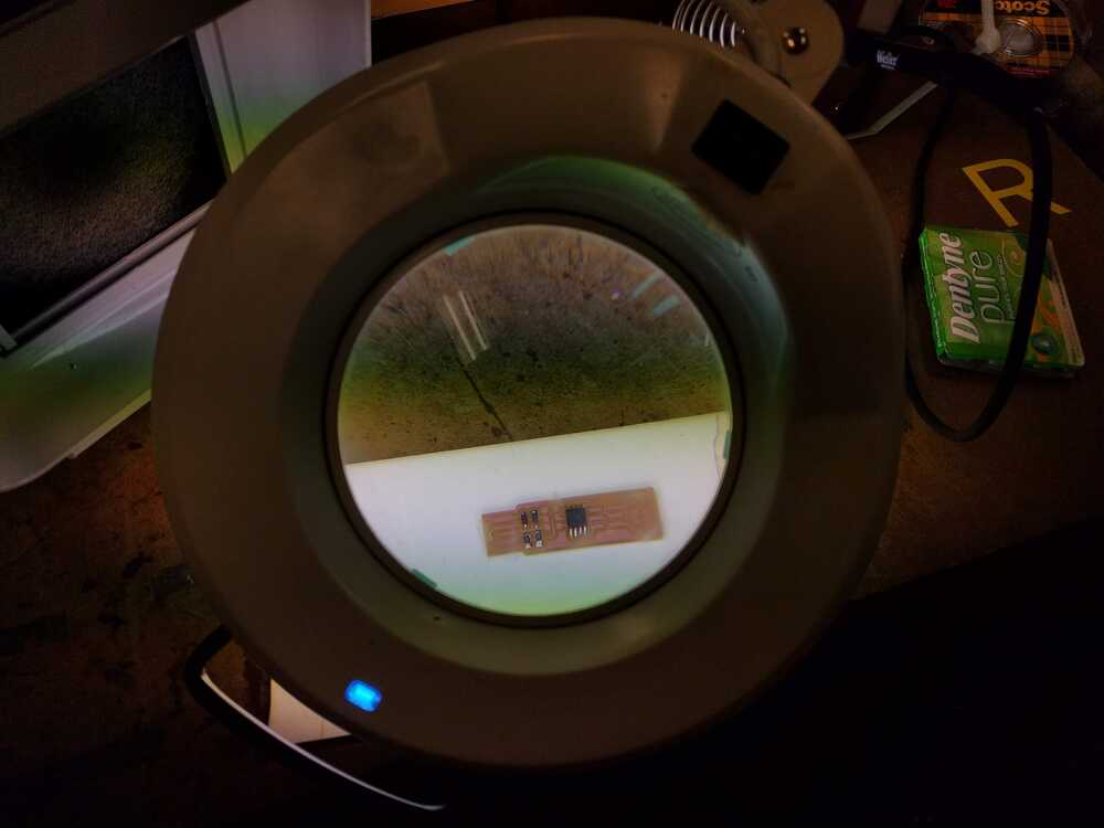
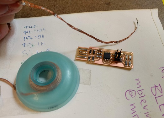
The board taped to a peice of paper:
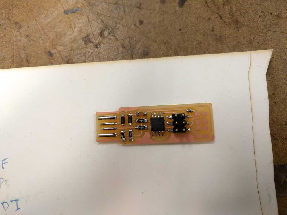
The board after everything except the LEDs (which are optional) are soldered on:
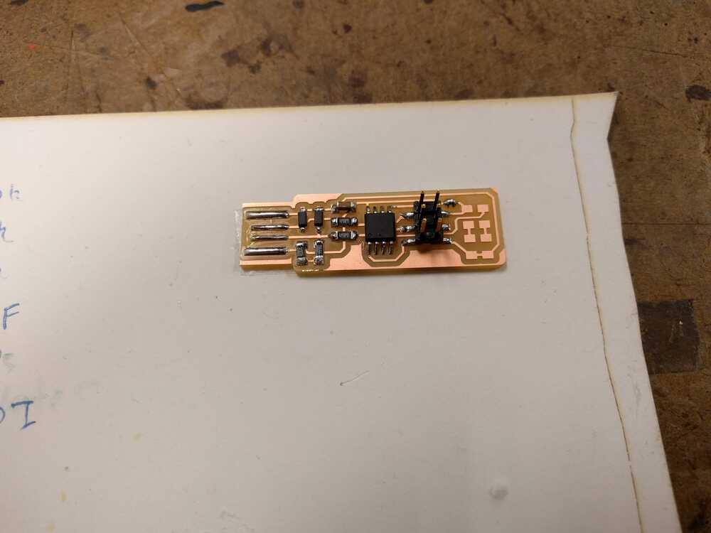
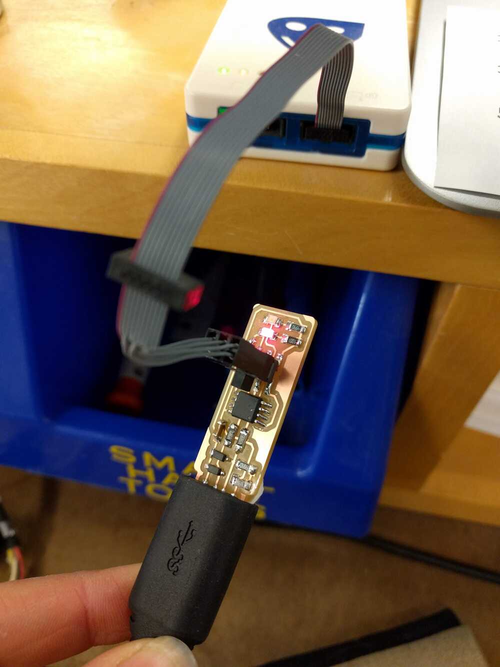
After I completed soldering my board (I ended up adding the LEDs) the last step was to program it to become a programmer!
The first step was to plug it into the USB connector to the arch-shop computer and also hook up the 2x3 pins to the ---- programmer. The red LED light confirmed that my board was working so far! I did have to strategically jam it in to get it working (will need to adjust the solder on usb pins to fix this). I followed Brian's instrucions again for this, but my key notes on his process are to make sure that when you're using the --- server on the computer that all your USB connections/file are in the server and not on the windows side.
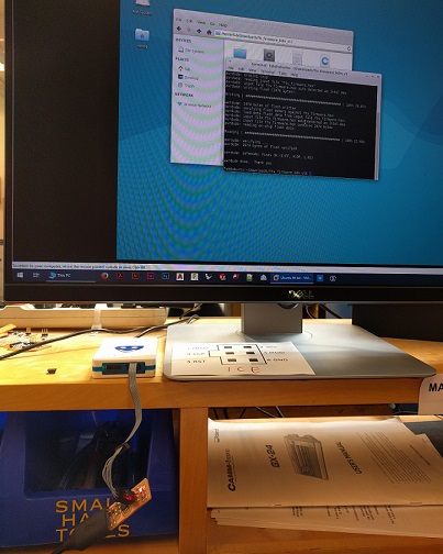
After successfully programming it the command line gave me a happy confirmation
Now that the board is a programmer, the final thing I have to do is disconnect the jumper connection