Week 9: Input Devices (sensors!)
Work Flow for this week: 1. Design board with sensors that will eventually be waterproofed 2. Design "mother board" that will control and collect data from the sensor board 3. Build the sensor board 4. Test that works with an Arduino 5. Test that the sensor board works with my board from the electronics design week 6. Build my new "mother board" 7. Test that the sensor board and "mother board" work togetherDesigning Sensor Board:
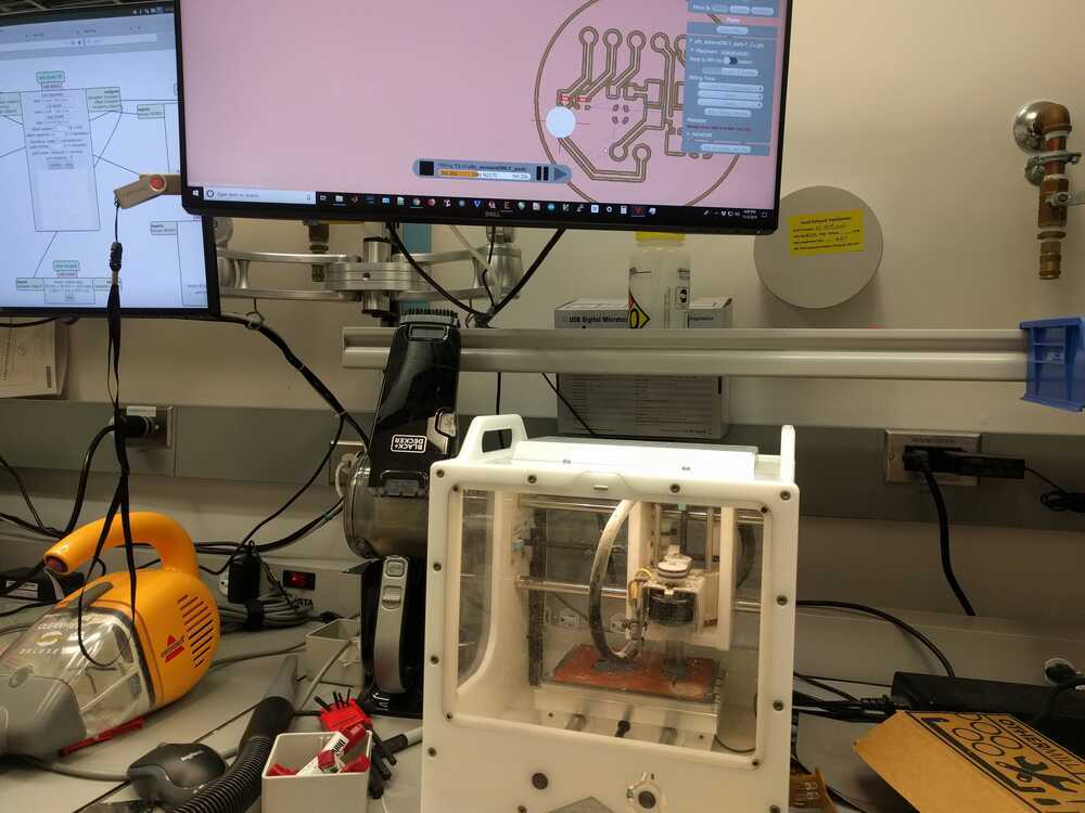
The sensors I am using: Temp Sensor This is for measuring water temperature Color sensor This is for measuring water measurment Hall Effect Sensor (Magnetic Sensor) Allows user to place object inside UFO to change a setting First I made a general schematic of my new board, including a AtMega16u4 microcontroller, microUSB programming/serial communication and sensors. My design of this controller setup is described in my week 7 page.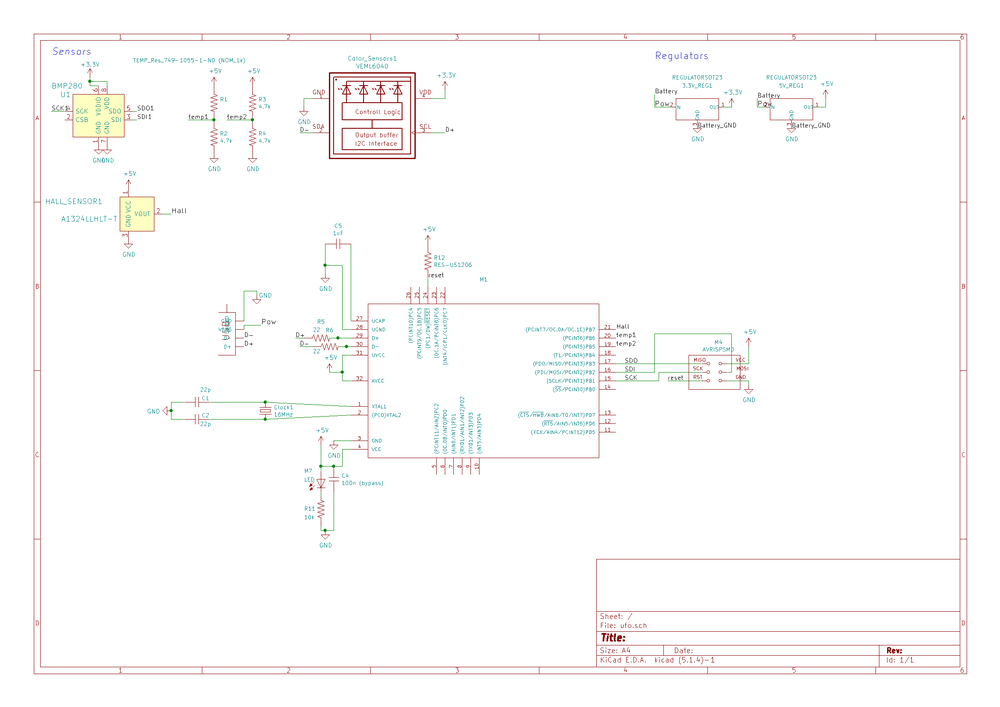
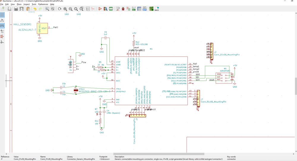
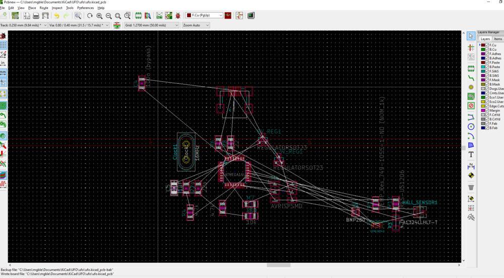
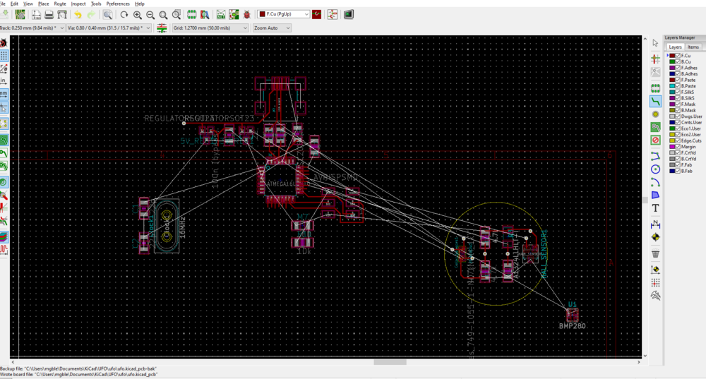
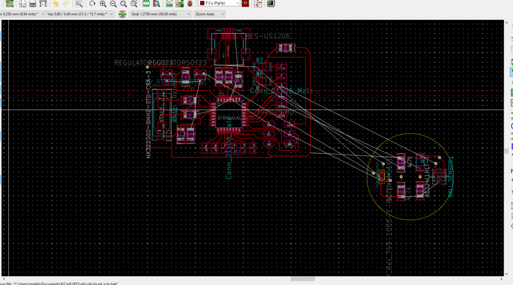
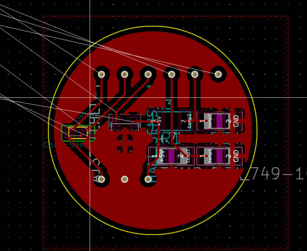
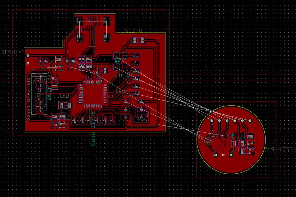
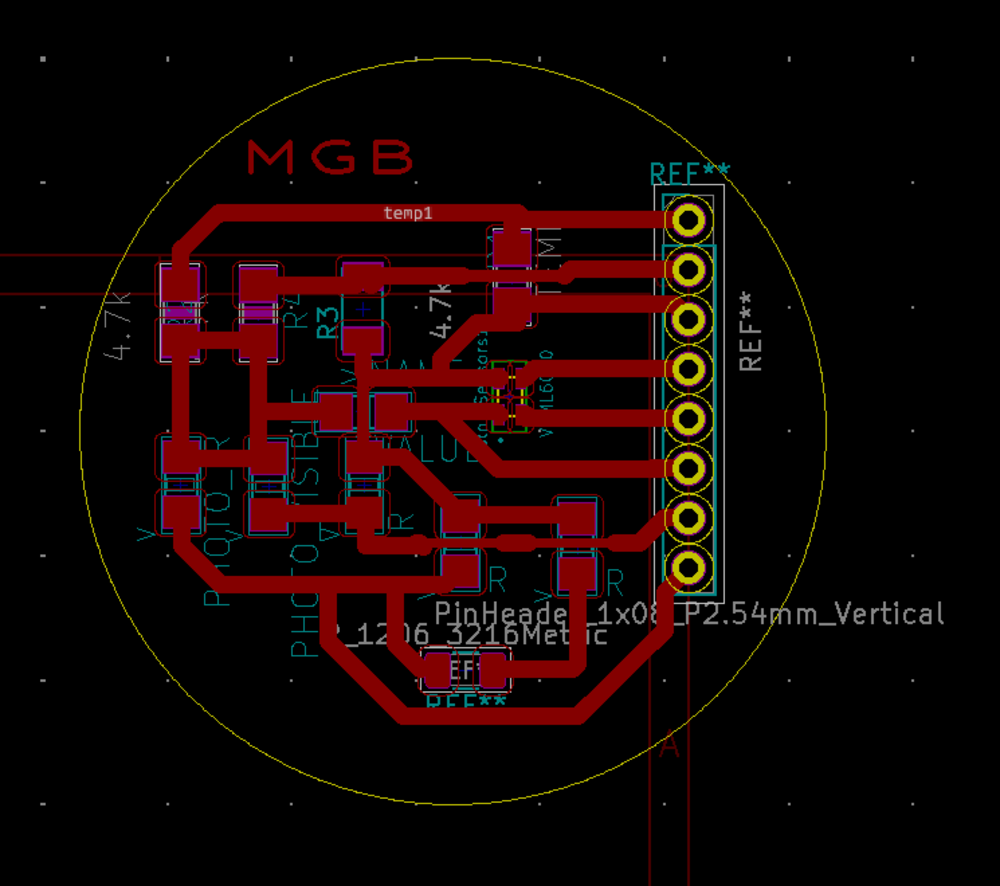
I added the hall sensor, thermistor, and optical sensor to the schematic. The connections for the Hall sensor and thermistor are simply Power, ground, and V_out (the thermisor is a Wheatstone bridge so there are two V_outs to create a differential output). The optical sensor gives a serial output so its connections are power, ground, D+ and D-. Final Schematic: Once the schematic was finished I moved on to creating the PCB layout. This took a couple hours to layout in a way that used the least about of Zero-resistors to jump over traces, etc. I grouped all the sensor components on one circular board and all the other components on another. Once I did this I saved sperate copies of the PCB files to KiCad so that I could print the sensor board and the mother board individually.
Building the sensor board
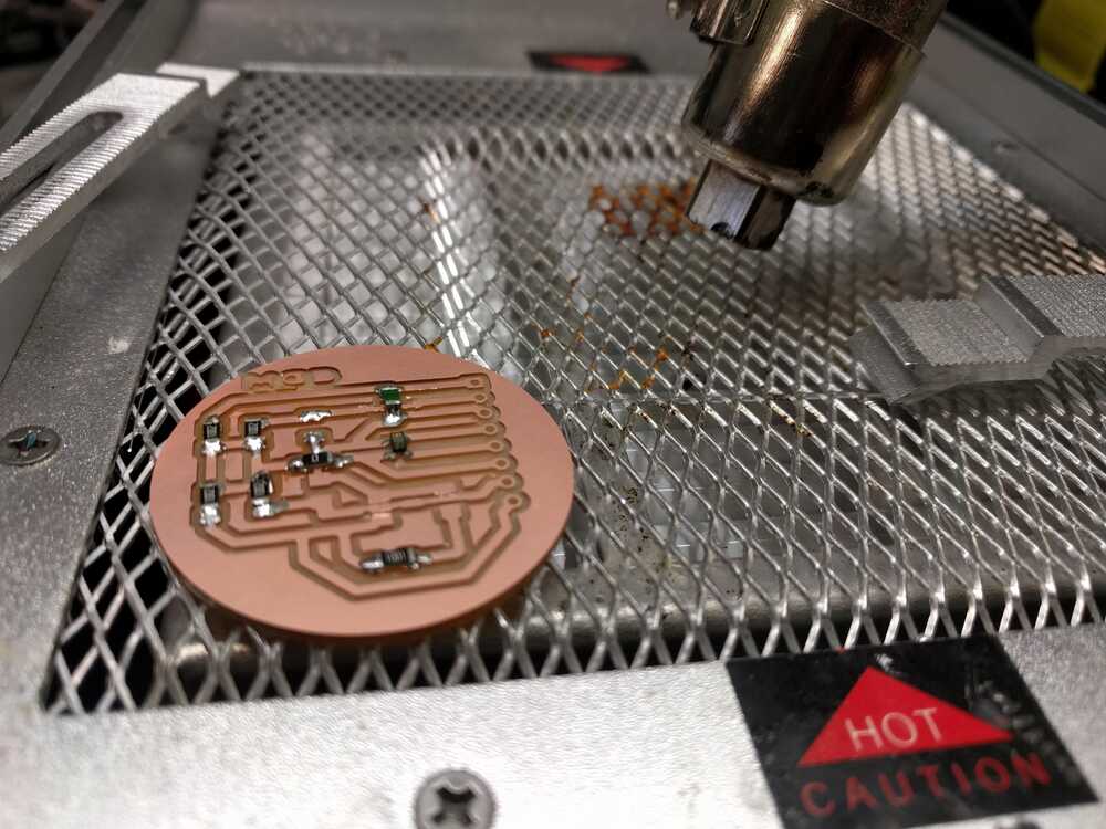
This was a wild procress!!!! Firstly- The hall sensor and thermistor are provided in the class inventory but I have to order the optical sensor. For this week I don't have the optical sensor but will when it arrives from DigiKey! First I used the Arch Shop Roland Mill to make my board. The milling went well except for the issue that I could not figure out how to mill out vias with Mods.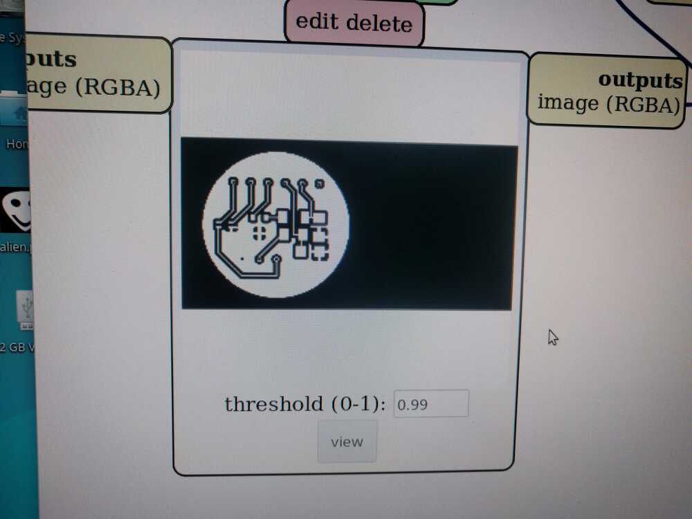
I went to the EECS office hours to see if I could drill out the holes, but instead I was encouraged to just re-mill my board using the OtherMill. I am a big fan of the OtherMill! I like how much more control I have when using it and that it will tranlate to projects I make after the class.
To use the other mill you have to plot Gerber-files of your PCB from KiCad as well as the hole files. This makes a total of 4 files that you then upload to the OtherMill program. Setting up your mill with the OtherMill is pretty intuitive. You designate which file if your traces, which is your edges, and which is your holes (KiCad gives you two files for the holes and the OtherMill only needs one, the one with the -PTH.drl ending).
The first board I made with the OtherMill went well. Here is the comparison of the Roland mill vs. the OtherMill boards:
I soldered the sensor components on and all was going well. However, the via holes ended up being really tight for the pins I was using. I could jam the pins in and this didn't seem like an issue until I realized that the pins were sticking to the traces around the via holes and making them peel off from the board:

This was really tragic because it made some of the traces tear. In reaction to this I went into my KiCad file and increased the size of the via holes from 1.2mm to 1.4mmm. I also increased the traces from 0.25 to 0.3mm.
I milled this board but unfortunately the holes seemed to be just as small as my first milling. This mades me wonder if the hole-file I was generating and sending to the OtherMill was actually representing the settings I made in my PCB boardset up. Instead of re-milling I carefully inserted the pins to the board, making sure to not make the traces around the vias come off the board. There were some close calls but I was able to do this with some patience. I soldered the pins to the via traces. Now that I had a configured sensor board I went to testing to see if the sensors were working!
Testing that the sensor board works with an Arduino
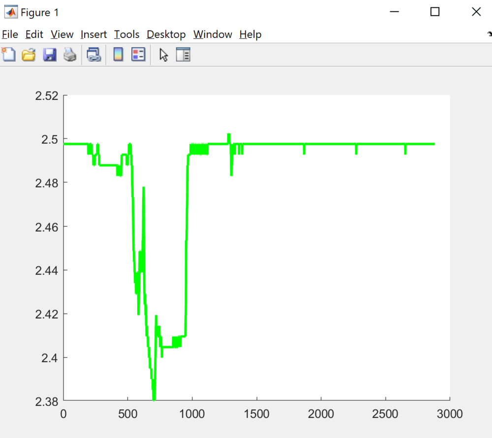
I wrote the following code to test the sensors://Morgan Blevins, MAS.863, Fall 2019 //This code reads the output of the Hall sensor and Thermistor const int hallPin= A0; //define Hall output locations const int t1Pin = A5; //define temp1 pin location const int t2Pin = A2; //define temp2 pin location int hall = 0; int t1=0; int t2=0; int temp= 0; void setup() { pinMode(tempRefPin, INPUT); //set button as an input pinMode(tempPin, INPUT); //set button as an input pinMode(hallPin, INPUT); //set button as an input Serial.begin(9600); } void loop() { hall=analogRead(hallPin); Serial.print("Hall = "); Serial.println(hall); t1=analogRead(t1Pin); t2=analogRead(t2Pin); temp = t2-t1; Serial.print("Temp 1 = "); Serial.println(t1); Serial.print("Temp 2 = "); Serial.println(t2); }This code allows me to watch the output of the Hall and thermistor sensor. I found that the Hall sensor and temp 2 pins were reacting as expected, however the temp 1 pin was not giving the expected output. The temp1 pin is connected to the thermisor, this means that if the thermisor experiences a change in temperature you would expect the temp 1 voltage to change. This didn't happen however. After some troubleshooting I found that the temp 1 voltage actually seemed to be following the output of the Hall sensor.I confirmed that the thermisor was working by measurming the resisantace across it while changing its temperature and saw that the resistance changed in reaction. So it's not a sensor issue but a board one! It seems to me that there is a short between the Hall and Temp 1 pins, but I couldn't see where this was happening. None of the pins seem to be too close or joined by any solder.
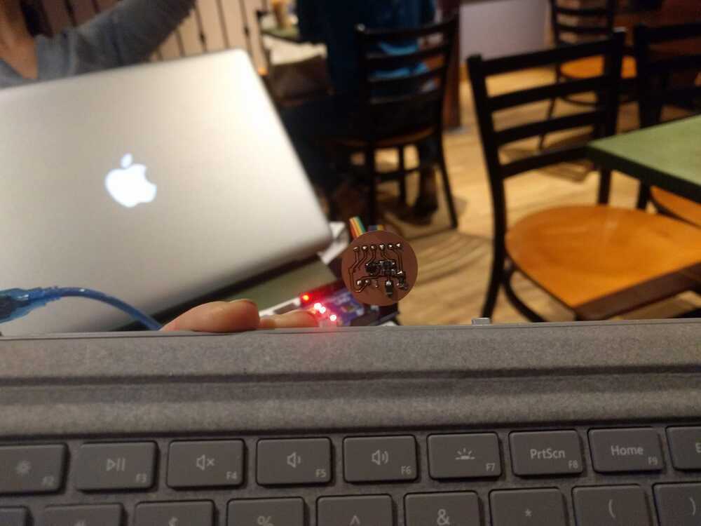
The resistance between the Hall-pin and temp-2 pins is 10K Ohms, which is what is expected. However, the resitance measured between the Hall-pin and temp-1 pin swung between 0 Ohm and 200 Ohms- AKA there is a short somewhere! I reviewed the example boards Neil gave for both the Hall and Temperature sensor and found that mine matched exactly (except that they were combined and on their own seperate board from the controller). This pretty much confirms for me that there is just some short on the board that I am unable to see and that is what is giving me these rersults. Hall Sensor Working:
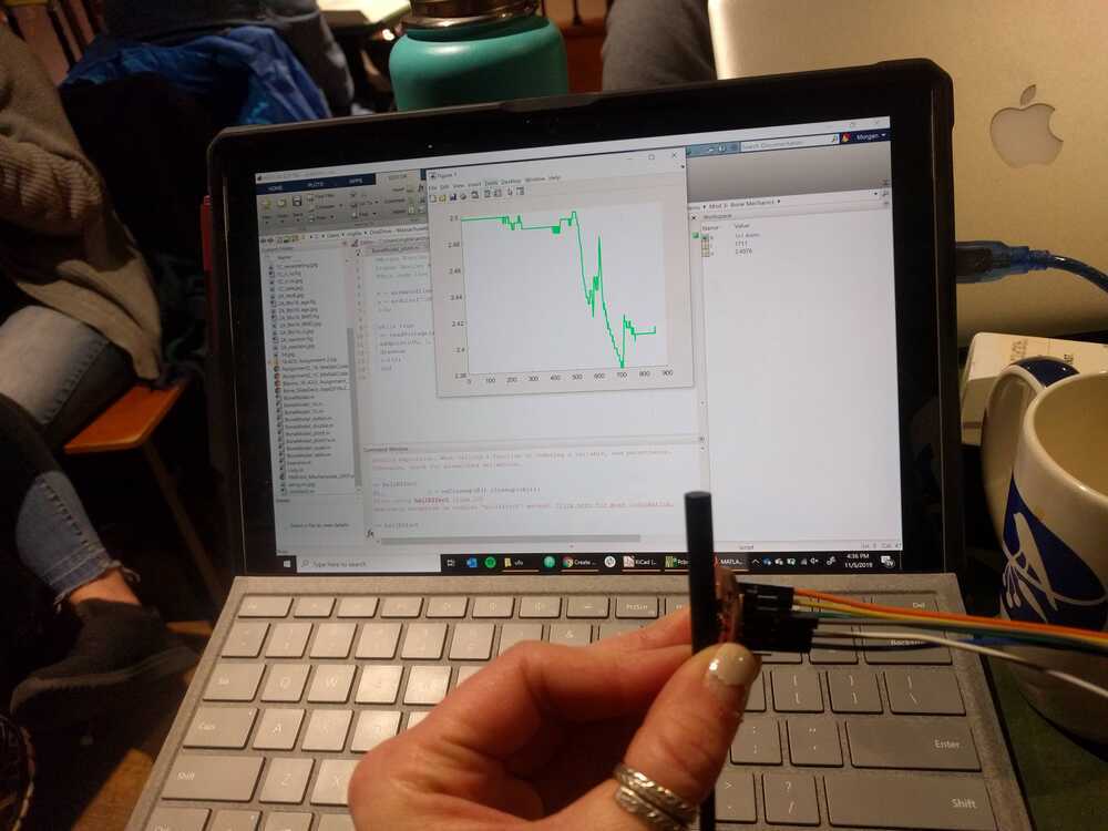
The next step was to test that the sensor board works with my board from the electronics design week: I modifidied my above arduino code to work with my board from week 5. The only changes needed were the board/programmer settings in the tool menu and the pin names of our sensor outputs. Here is the code:
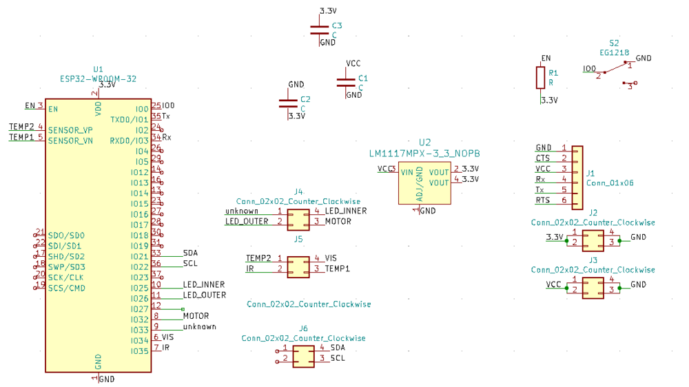
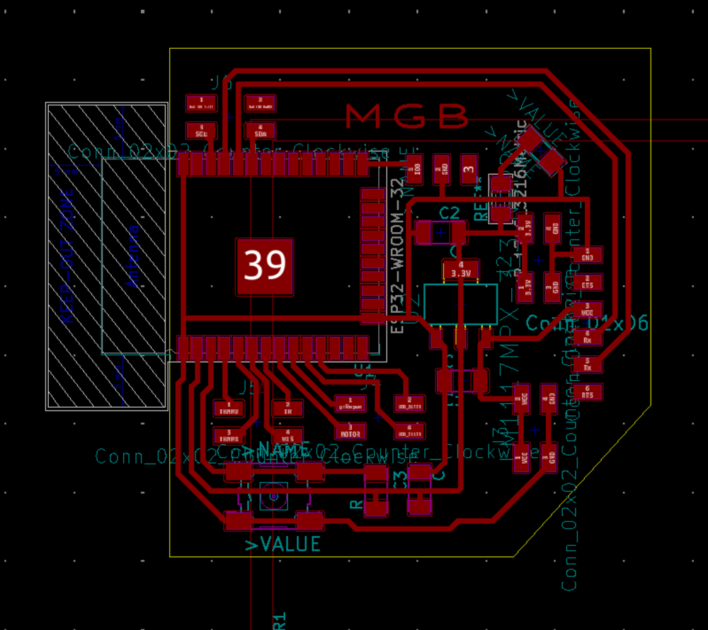
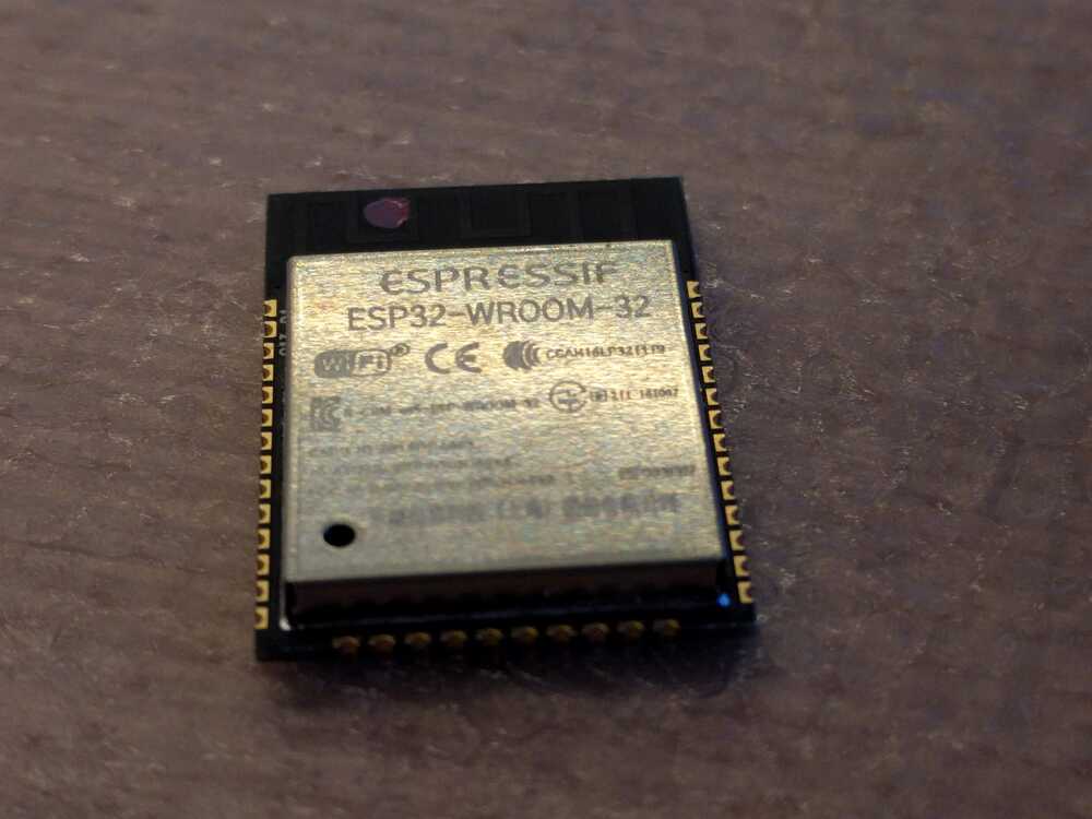
//Morgan Blevins, MAS.863, Fall 2019 //This code reads the output of the Hall sensor and Thermistor const int hallPin= A0; //define Hall output locations const int t1Pin = A1; //define temp1 pin location const int t2Pin = A2; //define temp2 pin location int hall = 0; int t1=0; int t2=0; int temp= 0; void setup() { pinMode(t1Pin, INPUT); //set button as an input pinMode(t2Pin, INPUT); //set button as an input pinMode(hallPin, INPUT); //set button as an input Serial.begin(9600); } void loop() { hall=analogRead(hallPin); Serial.print("Hall = "); Serial.println(hall); t1=analogRead(t1Pin); t2=analogRead(t2Pin); temp = t2-t1; Serial.print("Temp 1 = "); Serial.println(t1); Serial.print("Temp 2 = "); Serial.println(t2); }This sensor board continued to be fussy. I knew had to remake a sensor board for my final project so I stopped pursuing this design and instead built an ESP32 board that interfaces with my sensor board. I followed the same work flow as above but with the ESP32 and the thermistor, IR, and optical sensor, as well as the VEML6040 sensor. I designed this board with through holes to replace it, it’s pretty much the same except I added an IR led so that I could have a turbidity measurement.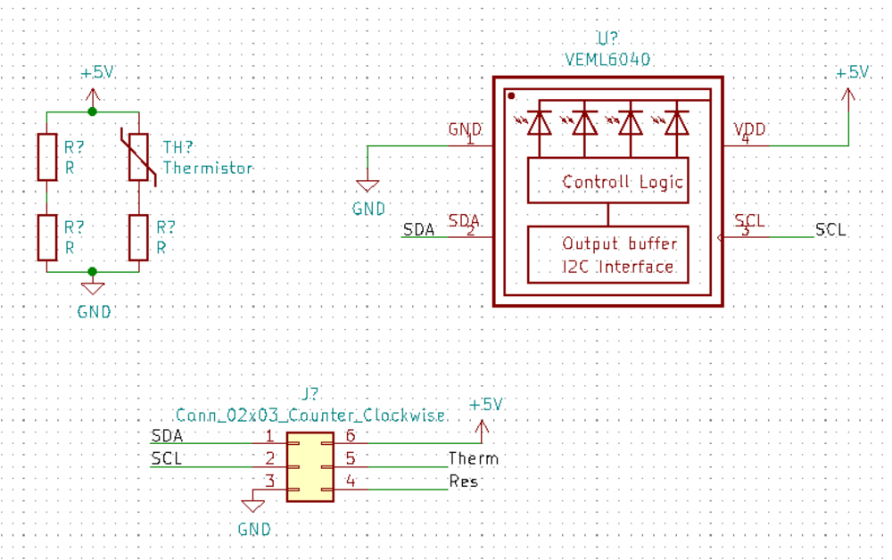
Next I created the ESP32 board to talk to it:
I needed to waterproof my board so I tested which epoxys were best for passing light. I panted layers of epoxy options on a metal sheet and when they were dry I saw how my sensor performed with them.
I programmed the ESP32 to talk to the sensors and read out their values on the serial moniter.
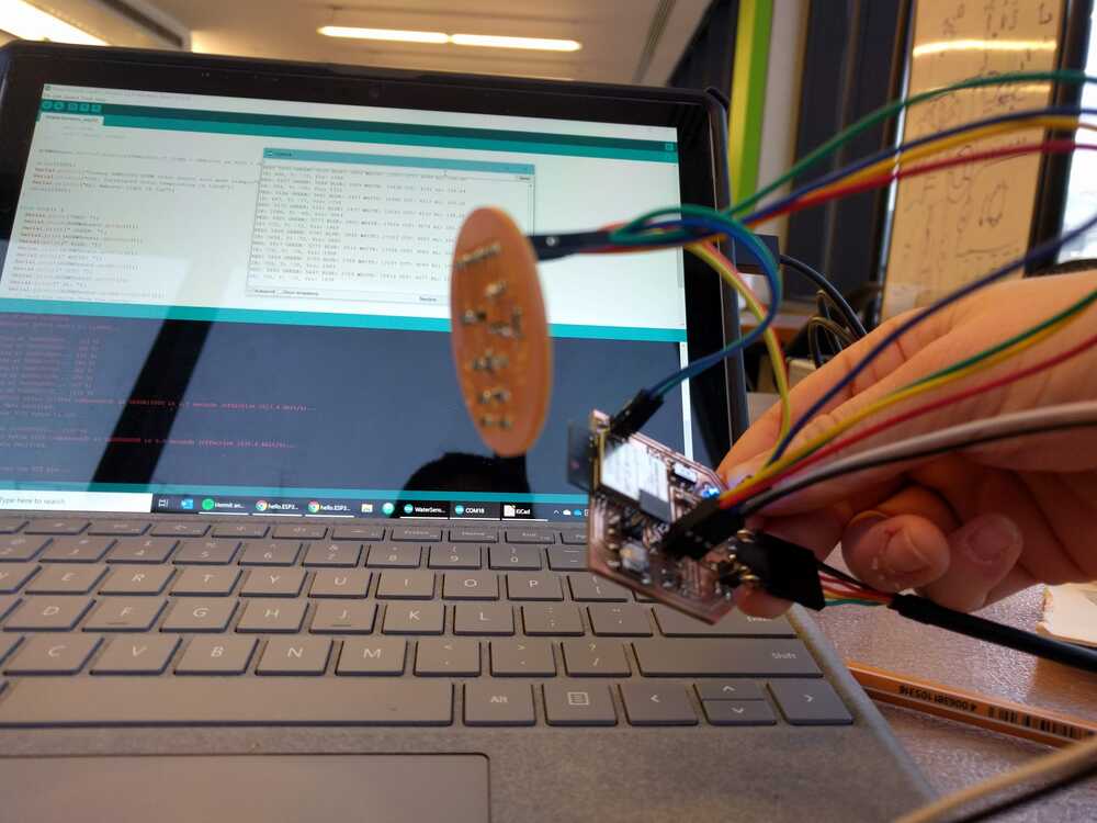
Right before expoy-ing my board I retested the board to ensure everything (cause you can’t really undo this!). The color LED worked but the radings on all the other pins were high. This was really strange. I took a multimeter and measured the voltages on the sensor board and those were fine… I FIGURED IT OUT! When using WIFI you can’t use the ADC2 on the esp32 and all of my analog input pins that I was using were using ADC2… YIKES. Now I have to make a new board with input pins that use ADC 1, aka GPIOs 32 - 39. SIGH. So my board works- it relays the sensor values to my serial port, just not during wifi com when the ADC is being used by bluetooth! This is continued in my final project :).