Week 12: Machine Week
I am a part of the Electronics and Communications sub-team. My first push was first setting up cuttlefish to run the motors.. My second push was to assemble the power distribuion board... My next push was aiding in the construction of the capacative touch pad for controlling the claw. We programmed it with Matt's code then I wrote code to make the output a string of the form "x,y,z" to be input into cuttlefish. Electronics/Coms team met in the morning of 11/22. The evening before I went through cuttlefish and got familiar with setting up the serial connections and programs. We connected the router board to my computer and when we refreshed the router panel we saw it update with the embedded programs! This shows that our router board is talking to my computer via the serial port. We then connected the motor board to the router board via an Ethernet cable (that we made). We powered the motor with a micro usb to ground. We loaded Jake’s example from recitation. We were not able to get the nested box within the router window (the window representing the motor board) to refresh. This means that we were not able to connect to this board. We remade our ethernet cable in hopes that it was a cable issue but this didn’t work.Jake came to the rescue and helped up troubleshoot in the arch lab. We made our own program in cuttlefish that talked to the serial port A of the motor board. When this didn’t work we tried port B, then port C. Next we went to the oscilloscope and used the program below to attempt to send data from the router board through port B. We observed the LEDs on the router board saying that signals were being sent. However, oscilloscope-ing the outputs of the serial port showed that those signals were not actually being sent:
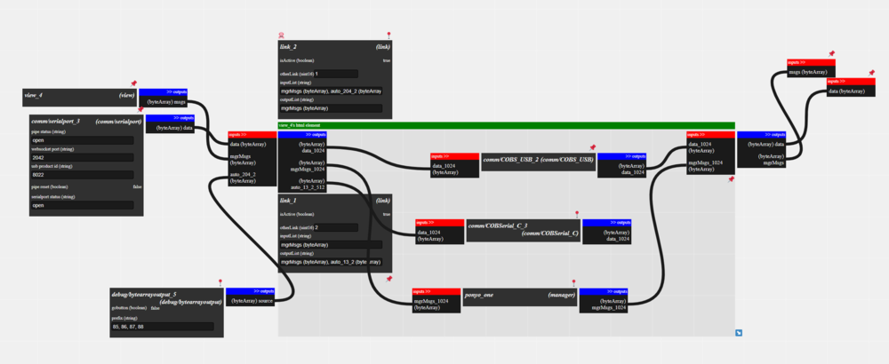
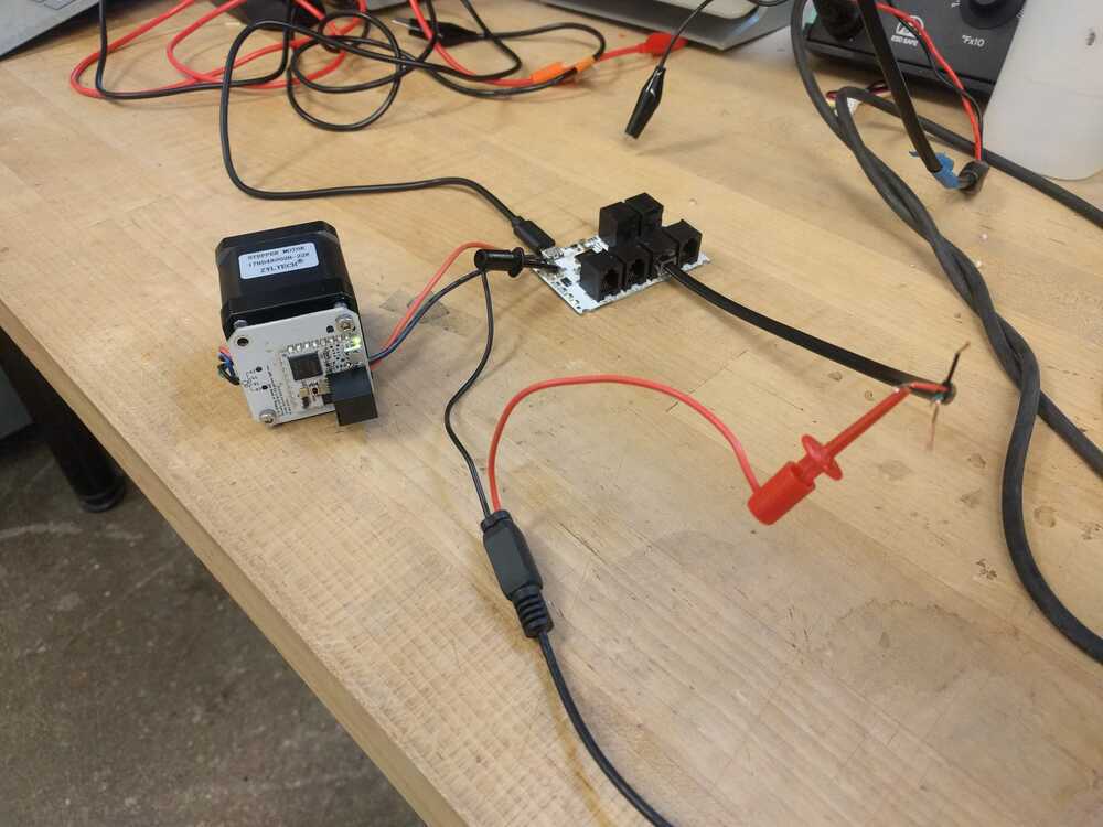
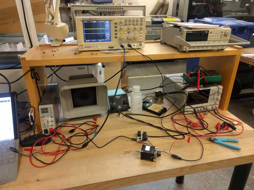
Jake luckily had 1 extra board. We connected it to the motor modules and were able to connect. By clicking “send hello” within the motor module window we saw data pass from the router to the motor board via LEDs blinking. Setting up motor control: I created the cuttlefish system below through Jake’s tutorial in class and through talking with him when he was helping me with the router board: I powered the motor with 24V from a power supply and set the current limit to 500mA (the motor is rated to ~350mA). I connected my computer outlet to the same outlet supply as the power supply. After making the system and ensuring that the motor was getting powered correctly, I couldn’t get it move in reaction to my array inputs. I confirmed that the data was being set from the router to the motor by observing the LEDs flashing, but no motor rotation was occuring. The power supply showed me that no current was being drawn during this either. I tried changing the states of some of the hunks and found that if I clicked “enable” on the motor driver hunk (made it true instead of false) I would begin powering the motor and my next input to the motor would be executed. I knew I was power the motors because (1) I could feel the motor slightly vibrating and (2) ~350mA was being drawn from the power supply. I troubleshooted why this was occurring. I tried seeing if the enable port would accept an input from a button and if I could send an array and them enable the motor. This didn’t work. After being sure that I followed Jake’s advice for cuttlefish and made my motor configured and powered correctly, I sought Jake’s help again. Assembling power distribution board: To assemble the power distribution board I first connected wires to the screw ports of the board. Next we printed the power mount Jake provided. Next I investigated how to connect the wires to the outlet port provided in our machine kit. I followed this schematic to help me figure out the wiring, as the documentation in the gitlab was a little hard to discern and I really didn’t want to short anything.
Source: https://www.instructables.com/id/Wire-Up-a-Fused-AC-Male-Power-Socket/icture 11/23/2019 Setting up Motors: Yesterdays issue: The only way I could get the motors to drive with the following set up is to manually click "enable" for the step driver, then input my position in the array and send it. I had to manually hit "enable" for each new array input. It would accept one movement and then not move again. If I didn't click "enable" the motor wouldn't move. I had it hooked up to a power supply and when enable is clicked it's drawing ~350mA as expected, but when it's not and I tried to send a new position it just sat at around 0mA. I believed I had the correct set up in cuttlefish, and was sure that I'm supplying 24V and enough current when needed.
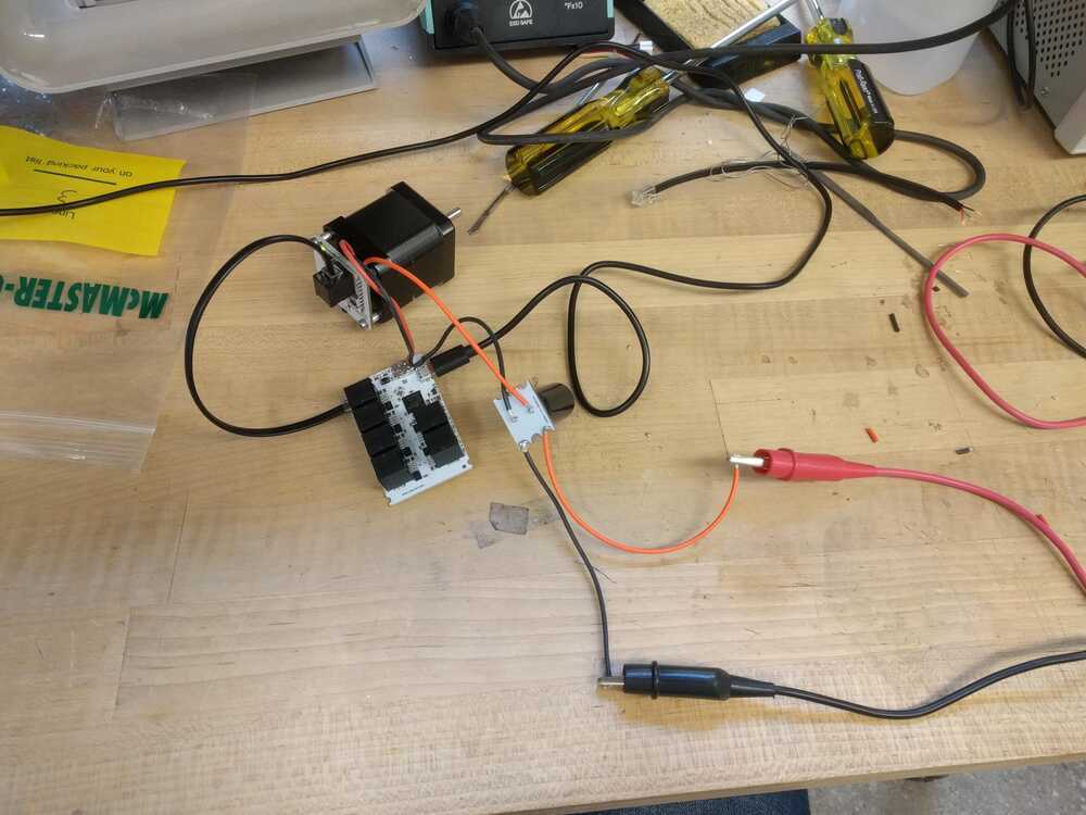
Ends up that I was forgetting to add in bypass capacitors to my system. From Jake: “when you rotate the motor the driver is drawing current - if you don't have enough bypass capacitance on the 24v lines, this will cause the voltage to drop suddenly, and the motor driver will brown out.” I added bulk capacitance, saw that the motor was functioning as expected! Then I configured the power distribution board and the motor continued to work in this configuration.
Next I hooked up a second motor to serial port B and after some trouble shooting, got this connection to work too. Motors at ports A and B will move the X and Y positions on the frame, while port C will potentially control the claw open and close (thought after talking to Jordan it sounds like we might just skip the router there and control the claw with the capacitive touch sensor board button!) 11/24 Programming Capacitive Touch sensor:
First we loaded Matt Blackshaw’s code to the board (with the 8th pad commented out). This was successful and gave us the following output. The first digit tells you which pad was just touched, the second digit is “0” for down and “1” for up. The sensitivity of the pads were a little finicky but the multi-meter told us the connections we solid, so we figured this had to do with the lo-fi construction and the threshold values that Matt had customized for this set up.


Next the mission was to get this pad to output a X, Y, Z position string (with Z always =0) that we could input into the motors via the cuttlefish system. We adapted Matt’s code to give the following output:
Also on this day I started testing running the motors on the fame:
Team meeting:
11/26 Documentation 11/26 Power Distribution: I soldered the ends of all the wires needed to power the motors and router board and finalized the configuration of the power supply & 3D printed distribution site. I was sure to test connections with a multi-meter before plugging in the power supply for the first time with the motors connected. Plugging it and and probing the motor modules with the multi-meter showed that the power was working as expected!

Touch pad: I finalized the programming for the capacative touch board. Currently this works by serial printing “x,y,z”strings of position that coordinate to your desired position on the frame. This program is not the prettiest thing and is a bit bulky, as I had issues with using char arrays (which would have made my code much cleaner and simpler via function calls).
We successfully uploaded this program to the capacative touch board were able to get is inputs streaming on cuttlefish!
However, when we attempted to add another serial port & link to talk to the router board the serial port hunk just kept “opening….”. Either we could had the serial port to the touch board working or we could have the serial port to the router board working, but never both at the same time. After a long time of troubleshooting I realized this likely wasn’t an issue I had the capabilites to address, especially with the motors still being troubleshot.
Motors: With both motors mounted, we were able to start seeing if the cuttlefish program worked in practice. First, using just serial port A both motors worked individually! Super exciting! The default setting in the saturn hunk is a pretty quick speed, I lowered this to 20 units to make the claw less jerky. I then wrote a cuttlefish program to drive both motors at the same time via serial ports A & B. REALLY STrange behavior ensued. Long story short- both X and Y motors are fine running from serial port A, but for some reason only the X motor will respond to serial port B. This means that the Y motor always has to be controlled by port A and the X motor always has to be controlled by port B. If you simply switch their ports the Y motor won’t work (though it will respond when you same hello), even though the path controlling each is exactly the same. I’m sure there’s a way to explain this but I couldn’t in the time I was working. This issue meant that for our initial tests I had to write my inputs as [Y,X,Z] which was really annoying, but this was faster than rewriting the cuttlefish during our testing. I rewrote a cuttlefish to link serial A with Y and serial B with X but as of 11/27 morning have not attempted to run it. Troubleshooting cap board: Once the claw was installed we had every component in place! A key moment in this process was when the motors worked but the claw as not responding, through evaluating the claw board and probing with a multi-meter we found that the button controlling it accidentally got soldered to a MISO pin rather than to ground, rewiring this fixed our issue and the claw was running!

Status as of electronics & control 11/26 evening: With the work I did, via the array interface on cuttlefish the user can control the position of the claw and via the button on the control/touch pad the user can open and close the claw to try to pop balloons! The capacative touchpad can load serial inputs of position to cuttlefish but can’t talk to cuttlefish at the same time as the router board.


