How to Make(Almost) Everything: Chris Wang

Final Project

Kinetic Couture

Planning

Initial Thoughts

I chose to make this project because it allowed me to explore my desire to create couture, but also utilize the skills I would learn from the class. Casey Curran’s sculpture for Iris Van Herpen was a crown that was essentially flat, so by placing it onto my shoulders, my project would be slightly complicated in that it would be bent over an object(my body), which would add potential design complications and friction to the final movement. I thought that this original sculpture was extremely aesthetically appealing and exhibit ready, so I didn't anticipate creating the most beautiful piece, but set the expectation at creating a sculpture that worked functionally and was somewhat attractive. I have very little experience in CAD, so this was a skill that I needed to improve a lot on in order to get anything done for the project, as most of it was likely going to be 3d printed.

screenshot screenshot

Dividing Work

I first created a plan to divide up different components of the project to tackle. I would need to design my own joint that would allow for the feathers to move, but also spring back to their original form so that the wave could move freely in any orientation. I would also need to design the mechanism that would allow me to translate the rotational movement of a motor into a cyclical pulling movement that would create a wave with 8-10 feathers. The mechanism would need some type of tubing so that the strings that pull the feathers can be guided to each one tangentially. This would also include the electronic component, where I plan to use a simple input(such as a switch or a power button) to start the output of the motors. Since this was a wearable project, I realized that I would need to connect a battery pack(preferably rechargeable) to the electronics so that I wouldn't have to stand next to an outlet for the project to work. Then, I need to create a harness that would fit over my body snugly while also allowing me to mount the project onto it. I would need to CAD packaging that would store all my components neatly to fit onto the harness. Finally, I would design aesthetic components like the feather to make the piece look artistic while remaining fully functional.

Supplies

Upon immediately looking at the original sculpture, the only supplies I thought I needed were tubing, 2 motors, acrylic, a motor driver, and filament string.The original sculpture used brass pipes to guide the strings to the feathers. I enjoyed the appearance of the brass tubes and also wanted to use them, but this was risky and expensive, so I consulted Rob and he suggested that I use copper tubing that was malleable but also held a consistent shape. The flexibility of plastic tubing was also a consideration, but it would be difficult to hold its shape when placed over my shoulders.

Spring Joint

Design

The original sculpture utilizes the feather itself to create a spring, where the string would pull on a point in the feather and bend it forward to create the motion, and the feather would spring back to its original form as the string loosened. I tried to create some prototypes of the feather being bent correctly, but this quickly snapped the feather. I then decided to go with my original idea, which was to make a spring loaded hinge that would allow me to switch the feathers in and out with other shapes and colors. I first designed a spring based on a spiral that I saw in the lab with a PCB holder.

screenshot

This took forever, but I eventually designed my own springs. However, they were HUGE and difficult to keep in the proper orientation, not to mention the tension required for the spring to tighten was too high.

They also didn’t print very well, so I decided to redesign them after a couple days of testing more configurations out. While doing this, I came across a torsion joint design on thingiverse.

This was much smaller, and also more stable because the spring was only being bent in one direction. I loaded this into Fusion and added another loop around the spring to tighten it up, and then printed it. Tada! This spring was so easy to squeeze, and it was tiny in comparison to the ones I had designed by myself. I was a bit frustrated that I had spent so much time designing my own springs and that Thingiverse was able to beat me to it, but I was very happy with the design that I was able to modify to suit my needs. I added more reinforcements to the sharper angles of the spring so that it wouldn’t snap after continuous use.

screenshot step1

I added a pressfit joint in the spring so that featehrs could be inserted in

step1 step1

Planning the Movement Mechanism

Rotation to Wave

I spent a lot of time thinking about how I would translate the rotational movement of the motor into a wave motion with the feathers. At first, my plan was to have 1 gear with all the strings tied onto it rotationally dispersed. The gear would rotate, which would tug on the strings in cyclical motions, which would eventually translate to a wave. There would be tubes arranged in a circular pattern around this gear, which would lead to each individual feather. However, daydreaming about this movement literally every free second of my day made me realize that the strings would get tangled together, and not free themselves on every rotation like I thought they would. I made a very crude mockup of this to prove my theory with a cardboard gear with several strings attached to it.

step1

I then researched the actual design made by the original artist Casey Curran to figure out how the movement worked without tangling the strings.

It appears that a rotating circle had a bearing with an additional smaller circle placed on it. The strings were attached to the smaller circle, and the smaller circle would be rotated around by the larger circle, tugging the strings around its circumference and creating the wave motion. The strings wouldn't tangle because the smaller circle would rotate around the larger circle, but its orientation would stay the same as it was placed on a bearing with a balanced number of strings. What is interesting about the placement of the strings was that there were no strings attached to the top of the smaller circle, probably to prevent it from changing its orientation and tangling the strings.

step1

After this, I spent an entire day at the chalkboard sketching out how the placement of different strings on different parts of the smaller circle would translate into a continuous wave. There was a decent amount of math involved here, and even though it wasn’t formulaic and methodical, there were many factors to consider that made my head hurt for days. I was happy to know that most of my instincts were correct with the motion, and that I would also still need to have tubes creating a circular pattern around the strings to guide them to each individual joint.

step1

If the smaller circle was rotated 180 degrees from its original position, it would allow for a feather to undergo a complete movement up or down(or in between), and the other 180 degrees returning to its original position would be the opposite. Because of this, I thought that I needed to know exactly what angles to connect my feathers to. If my wave was made of 4 distinct positions, I could only have 8 or 12 feathers. It would be more difficult to have 10 feathers like I originally planned, but I would explore this later on and just stick with 8 for simplicity. The direction of the rotation also played a part in assessing how the wave would move, as well as the placement of the string guiding tubes on the back. I decided that I would test my math later on, as I was getting too caught up in the nitty gritty details when I wasn’t even sure if it would work or not.

step1

Harness

Fabrication and Design

At this point I decided to take a break from understanding the exact mechanics of the sculpture, and started designing the harness that it would mount on. The original sculpture was made flat and placed around a head, so it would be much more complicated to build this bent over someone’s shoulders. The plan was to create a harness that would be easy to 3D print and modifiable for many different purposes. Instead of choosing to 3D scan myself and use rhino to create a harness I could 3D print, I decided to take a more familiar route and sculpted a harness out of wire.

Upon examining the rudimentary but accurately fit harness I had made, I realized that I could divide it up into 4 pieces so that it could be printed flat and later assembled to fit snugly on my chest. 2 pieces would go over each shoulder, and would be printed on their side so that they could be curved, while the other 2 pieces would be the front and back that could be printed flat. I marked these breaks onto my wire sculpture and then traced them onto a sheet of paper. I took a couple measurements that were key to understanding the proportions(roughly) and then scanned these photos and used them as canvases on Fusion360 to design the harness.

screenshot

I printed it afterwards in 3 separate prints. Not bad after assembling it with hot glue, but without the press joints, it fit poorly because the pieces bent at the glued ends, and also wasn’t the exact shape I was going for in the final. However, it fit well on my shoulders and did not consistently ride upwards.

step1

I realized that I didn’t have an exact clue of what I was looking for in terms of shape and aesthetics after this, so I took some important time to sketch out concept art for how I wanted the final sculpture to look. I wanted it to sit on my shoulders and not dip far into my torso, but I also wanted it to look neat and couture and not unflattering and poorly fit. Upon examining these photos, I photoshopped the concept art onto a picture of myself to bring my ideas into real life in Procreate, and then redesigned the harness with a more intentional aesthetic edge on Fusion. I adjusted the width of how the sculpture would lay on my shoulders, added press fit joints, and even included a divot for my shoulder blade to flex how well it would fit.

The harness turned out amazing, and after a couple more iterations, I was able to add in the tubes that would lead each string to each joint and then move on. Aesthetically, this looks like a harp.

step1 screenshot

Mechanism

Fabrication and Design

I decided that I would create the mechanism on Fusion360, 3D print it, and then test it out physically in 2D with a cardboard model and a couple of the joints I 3D printed ahead of time. I had grown too attached to the calculations involved, and thought that just by making it, it would save me a lot of time. I first designed a circle with a negative of the DC motor’s shaft in the center to rotate. I made 6 of these negatives and printed them out many times to understand the exact tolerance that was required to insert a metal shaft into the PLA printed circle, similarly to how I did with the feather and joint(which were both PLA). I found the tolerance to be .2, as the motor shaft inserted tightly into the hole without jiggling. I used this tolerance to design the final large circle, and then added a bearing that I extruded for the smaller gear to rotate on top of.

step1 step1

I then designed the smaller gear that would be placed on top of the bearing, and used a .3 mm tolerance so that it could rotate on the bearing. I wanted to create 10 holes on the top of the gear so that I could tie the strings that would pull the fathers onto it, so I created a circular pattern for 14 holes, and then deleted 2 on the top and 2 on the bottom so that the gear wouldn’t over-rotate and tangle the strings. I made a sweep with the holes so that they could exit out of the side of the gear and allow for it to rotate without getting caught as well, and then printed it.

screenshot

2D Modelling

After procrastinating the actual mechanism that would translate the rotational movement of the motor into a cyclical pulling motion, I decided to build a 2D version of the feathers and the gears before making it onto my body. I chose to model only a half of the final project for simplicity, as I had planned on using 2 motors for each side of my body anyways. I printed 8 joints and 8 feathers(I quickly designed and extruded these on Fusion360 with a .3 mm tolerance joint to attach it), and then glued them in a line onto a piece of cardboard. I then cut a hole at the bottom of the cardboard to insert my motor and the 2 gears that would rotate and create the wave motion. I then glued 8 plastic flexible tubes onto the cardboard that would begin arranged around the motor in a circular pattern, but then lead to each feather. Finally, I strung every feather and guided the strings through the plastic tubes and tied it to one of the holes on the smaller gear. Each string would have a different amount of tension on it to create the wave. I assembled the motor to the gears, and then plugged the motor into a power source.

step1

Motorizing

The results were initially fantastic, because the rotating motor successfully translated into a wave motion! However, the strings created an ENORMOUS amount of tension on the motor, so the motor could hardly rotate and eventually stopped. After consulting with Nathan, he provided me with several alternatives to the original DC motor, most interesting a 90 degree solarbotics DC gearmotor that was very cheap and somewhat bulky. I immediately latched onto this motor because the 90 degree orientation meant that it could be mounted onto a back flatly. I redesigned the larger gear with a new negative that would fit onto this motor, and then reattached this configuration with the new motor to the cardboard mockup I initially made, and IT FREAKING WORKED.

step1

I was so happy that I was able to find another motor in time, as this was past the order deadline on December 3rd for any supplies I needed.

Electronics

Recycling the ESP32 board

For the electronics, I recycled the ESP32 board that I had made for the week’s assignments prior to the final push towards the end. Nathan also gave me a L9110 motor driver so that I could power and communicate with the two DC motors. I first cut some wire to connect the motors to the motor driver, and then connected the 6 motor driver pins to 4 communication pins on my board+ ground and power.

Programming

I first cut some wire to connect the motors to the motor driver, and then connected the 6 motor driver pins to 4 communication pins on my board+ ground and power. I used the FTDI cable to program my board with my laptop, and I used this example code in order to turn on the motors. Success! I then modified the code so that the motors would move continuously counterclockwise so that the wave would smoothly pass over both sides of my chest.

screenshot step1

Connections

After getting this to work and uploading it onto my board, I unplugged the FTDI cord from my laptop and found a rechargeable phone battery. I cut off the end of a micro usb charger and soldered/sealed the two ends to 2 female pin connectors, and then connected those to the power and ground on my ESP32, and plugged the USB into the charger. Everything worked out great! I realized that I’d have to manually move the gears into the correct start position, but I was very satisfied with getting my electronics to work wirelessly.

System Integration

Packaging

I arranged all the electronics in the spacing that it would end up in on the back of the harness, and then took measurements of each of the components to design neat packaging that I could 3D print that would integrate all the systems of my project together.

screenshot step1 step1

Here is a sample case for the motors I printed out to validate my measurements.

screenshot

I also designed an intricate tubing system for the back that would allow me to arrange the tubes neatly around a circle so that the gear mechanism would rotate within it and pull the strings at different angles. These prints ended up being quite large and took a decent amount of time, but they ended up being perfectly fit for all the components, and everything wired neatly together in an exquisitely satisfying way. I designed a lid for the back that had an 18x20cm rectangle cut out from it so that I could slot in a sheet of acrylic. I lasercut the acrylic from the scraps leftover in the lab.

step1 step1 step1

Assembly

I began to assemble the sculpture. I inserted all the torsion joints into the front piece with superglue, used epoxy to seal all the electronic components into the back compartments, and then placed the back tubes on top of the electronics to guide the copper tubes from the front to the back.

step1

The copper tubes took an enormous amount of time to cut and bend to shape, and after doing so, I began to arduously handwire each and every single one of the 20 strings to the sculpture, beginning by tying one end of the strings to the torsion joint, and then feeding it through the plastic, copper, and plastic again and tying it to the smaller gear. After everything was fed through, I tensioned every single string to the correct calibration to create a wave motion, which took an even longer time. However, once all the pieces were connected, I turned it on and it worked. The biggest smile I’ve ever cracked at 6 am in the morning.

step1

Aesthetics

Afterwards, everything was glued together and the acrylic lid was slid into place. The final step was to print the "feathers" and press them into the joints. I chose to print actual feather shapes, but considered doing bones as well. Feathers ended up looking the most pleasing.

step1
step1

Basic Questions

Answered:

What does it do?

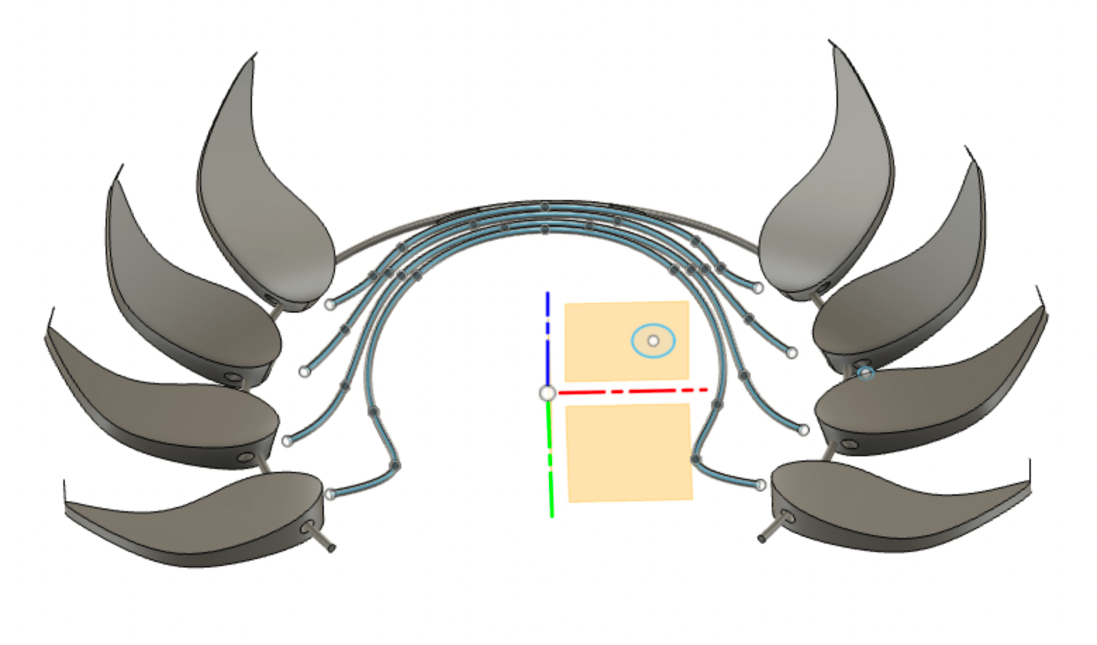
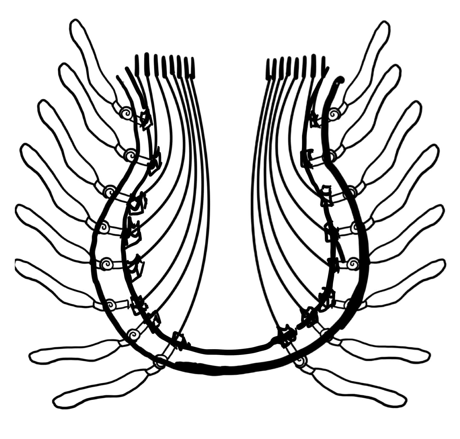
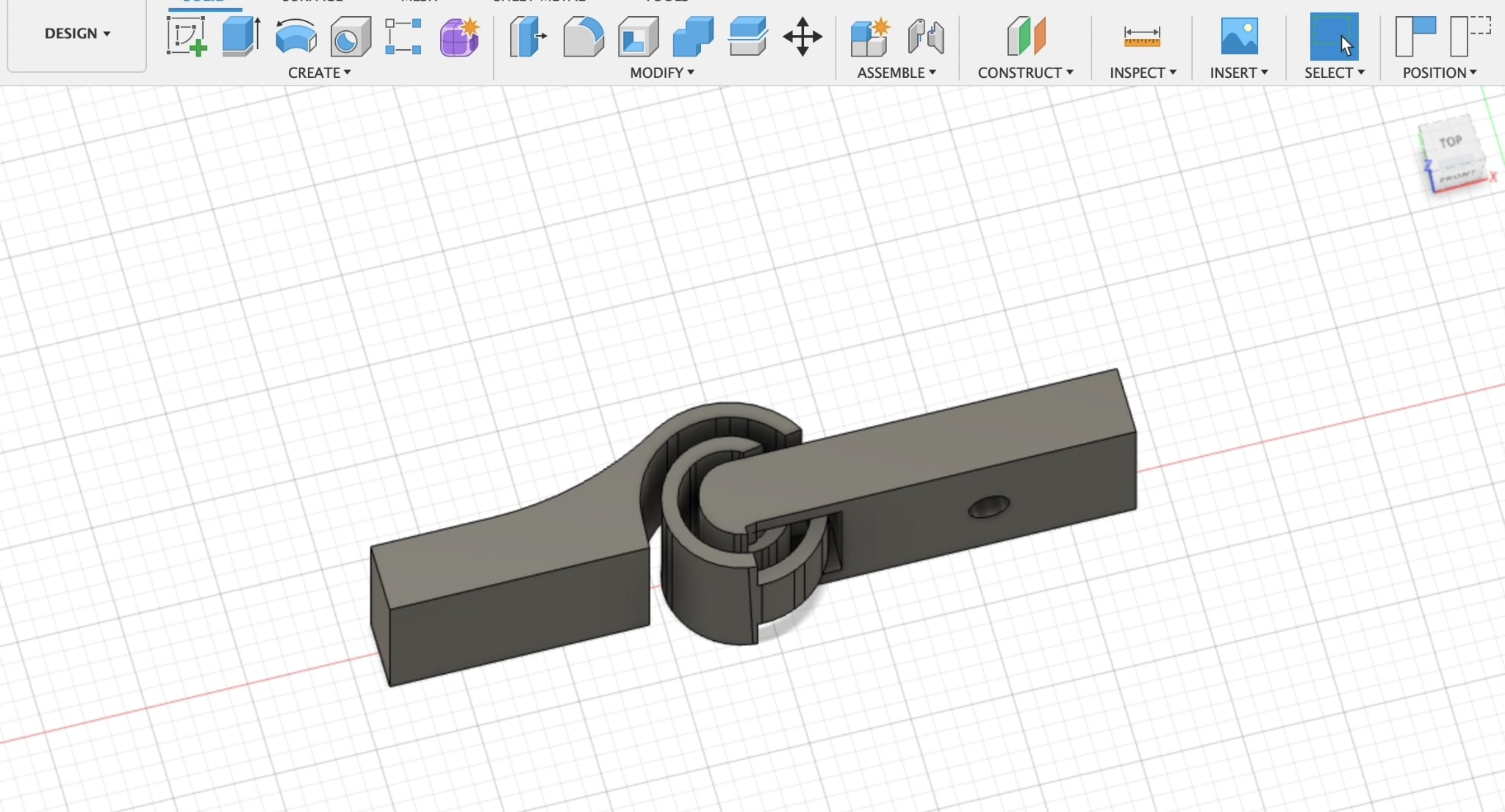
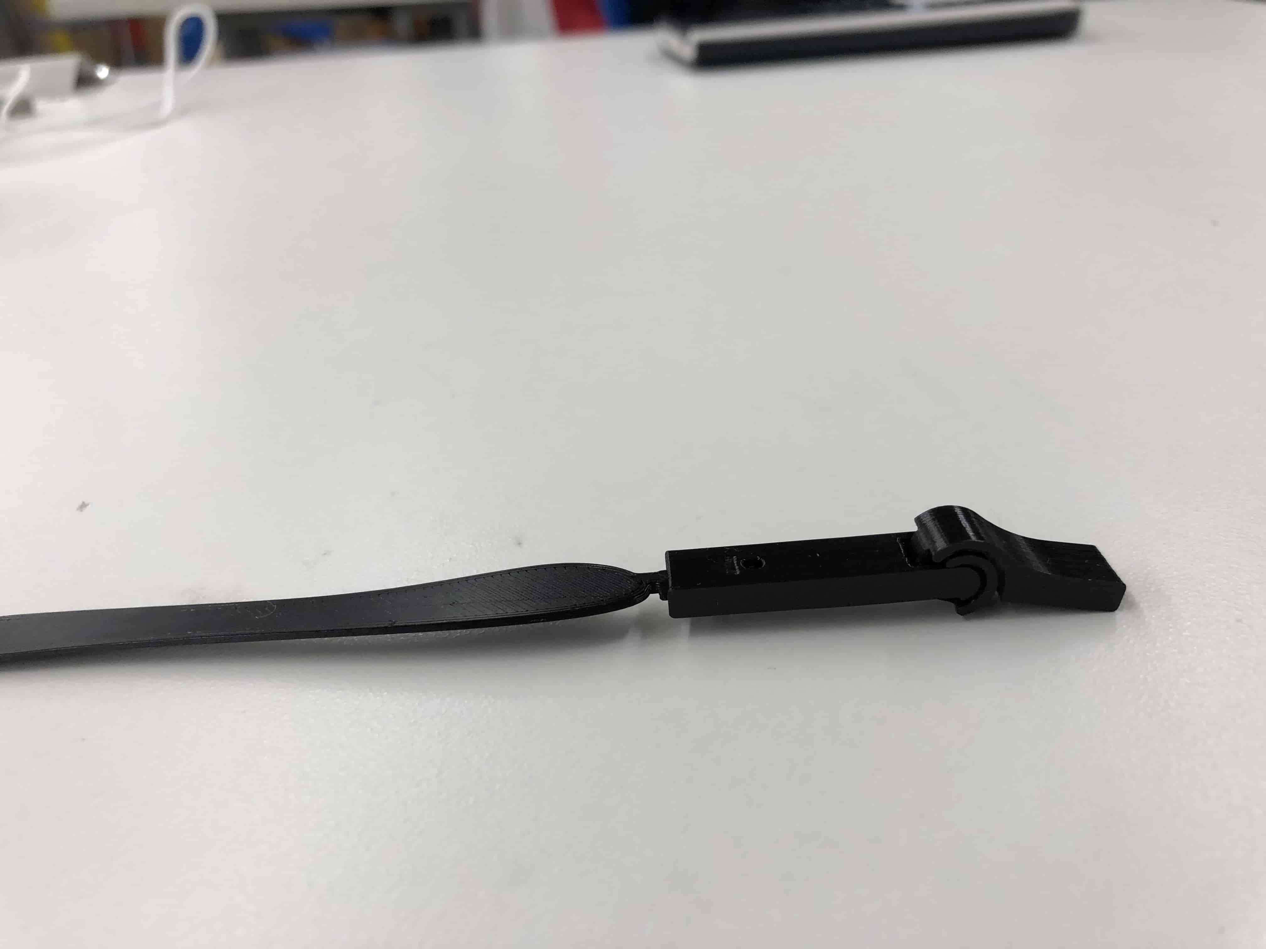
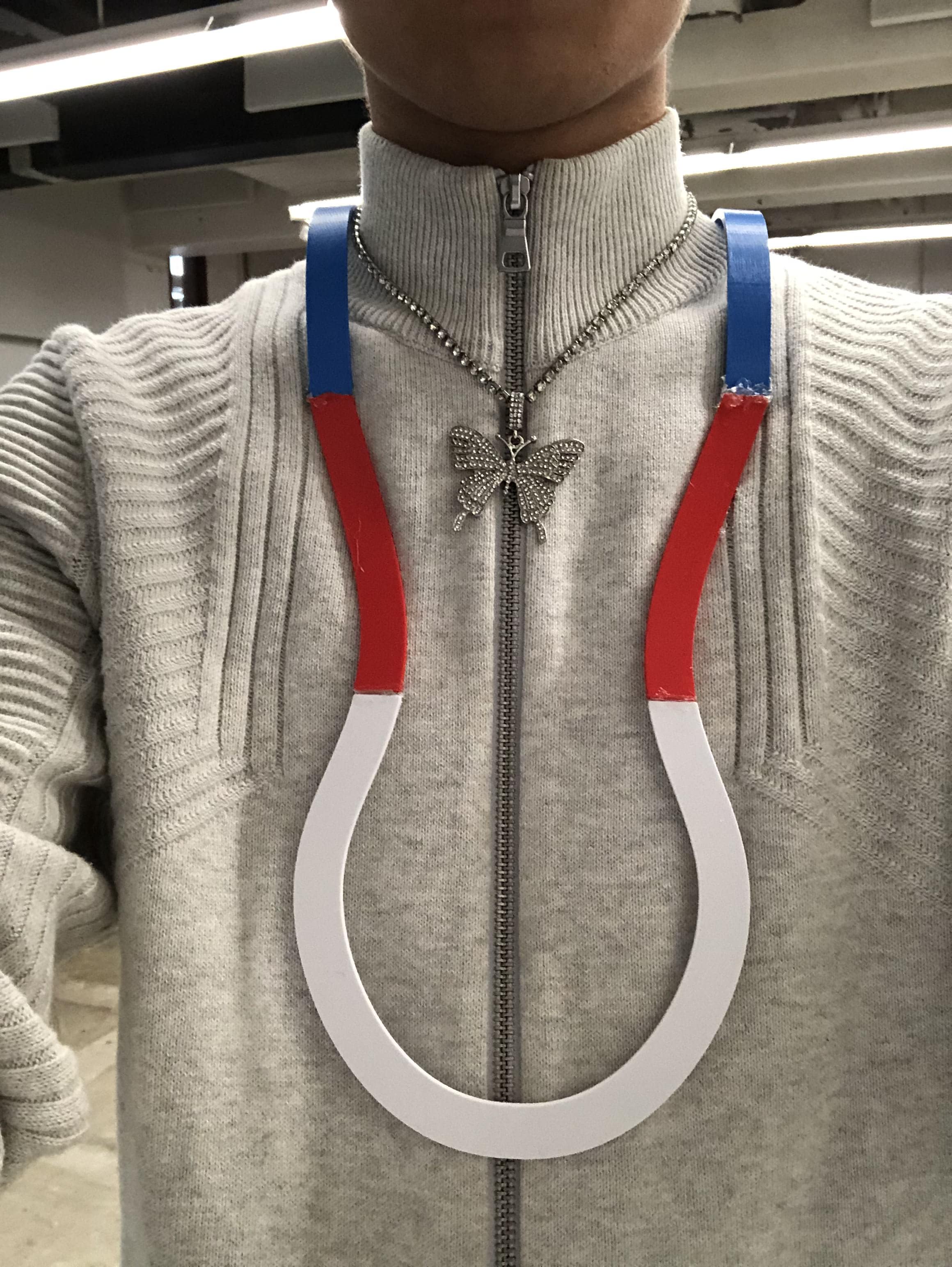
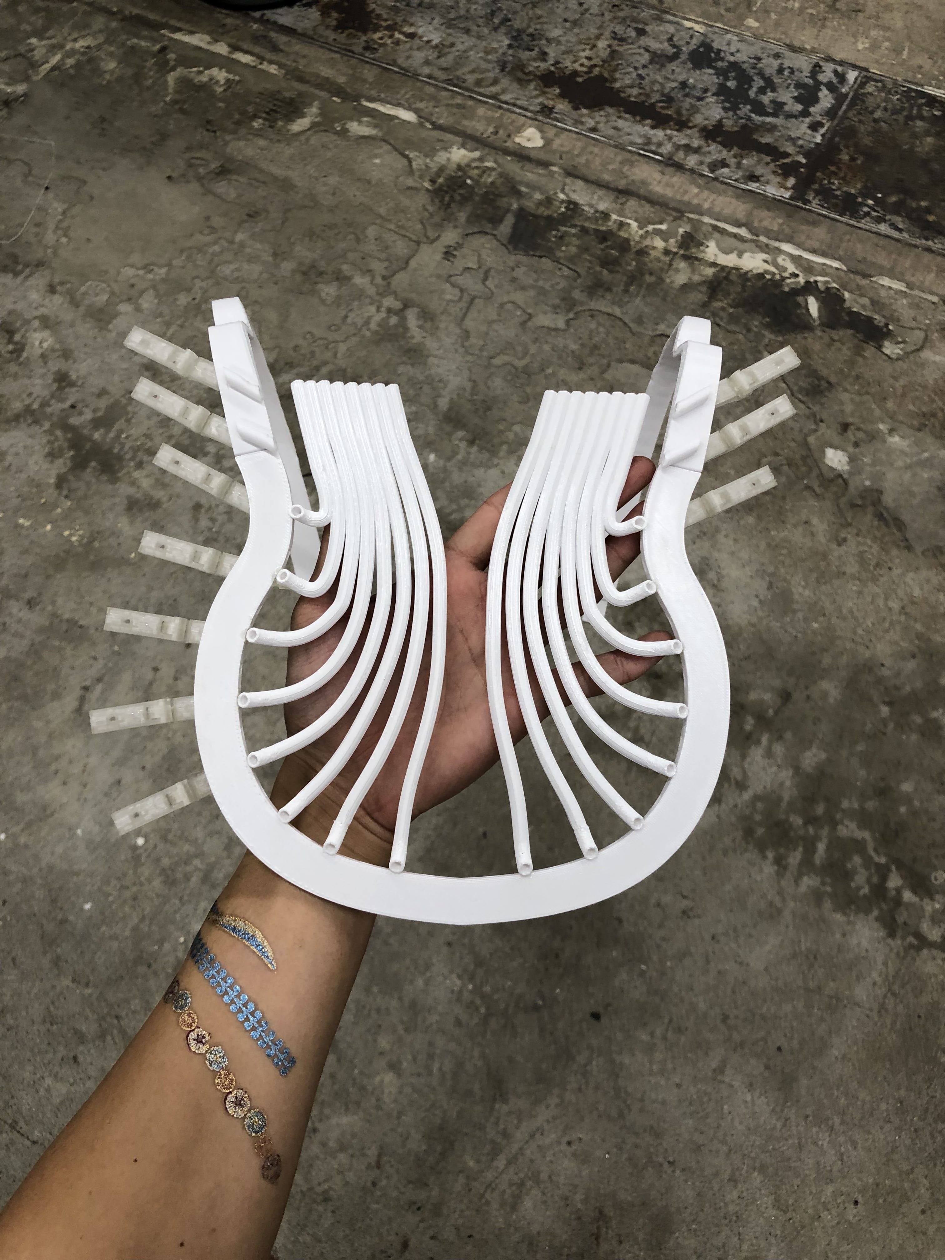
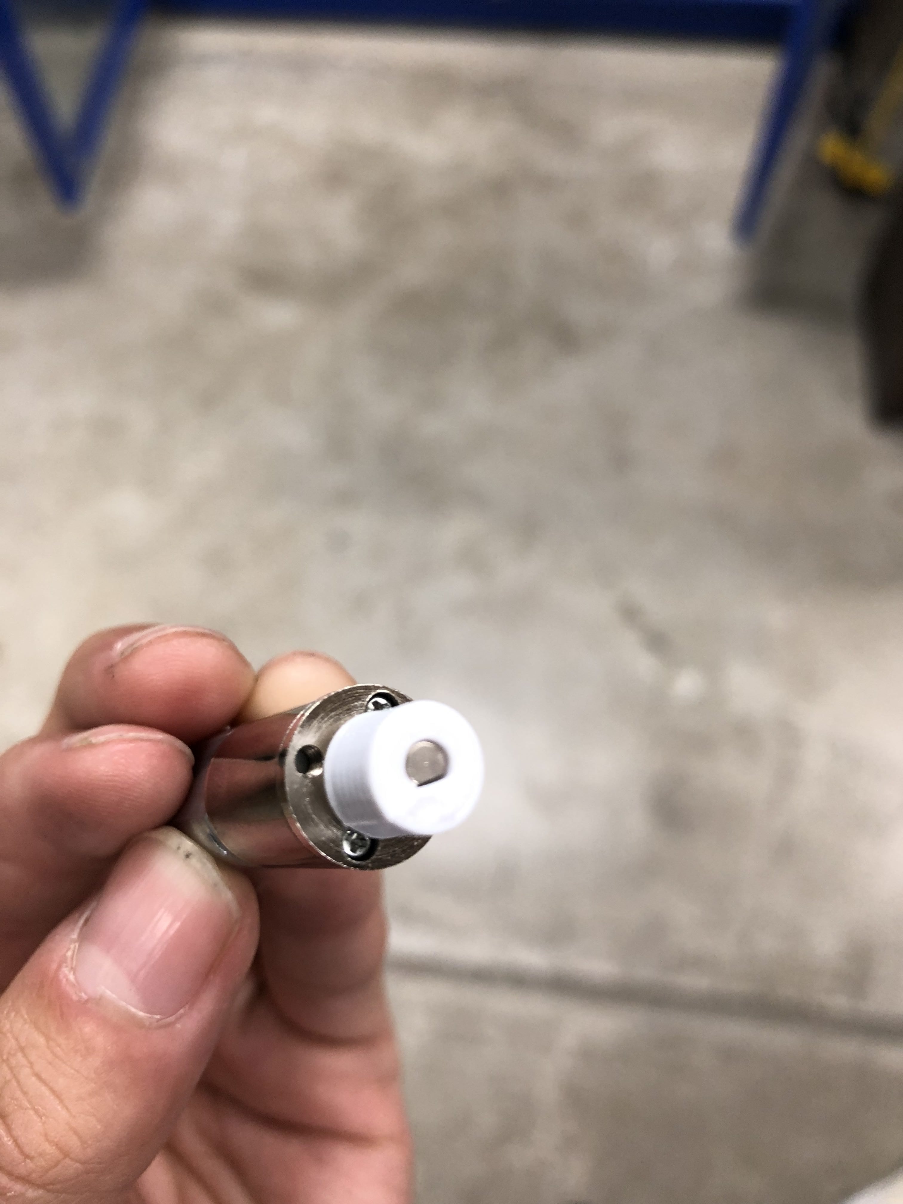
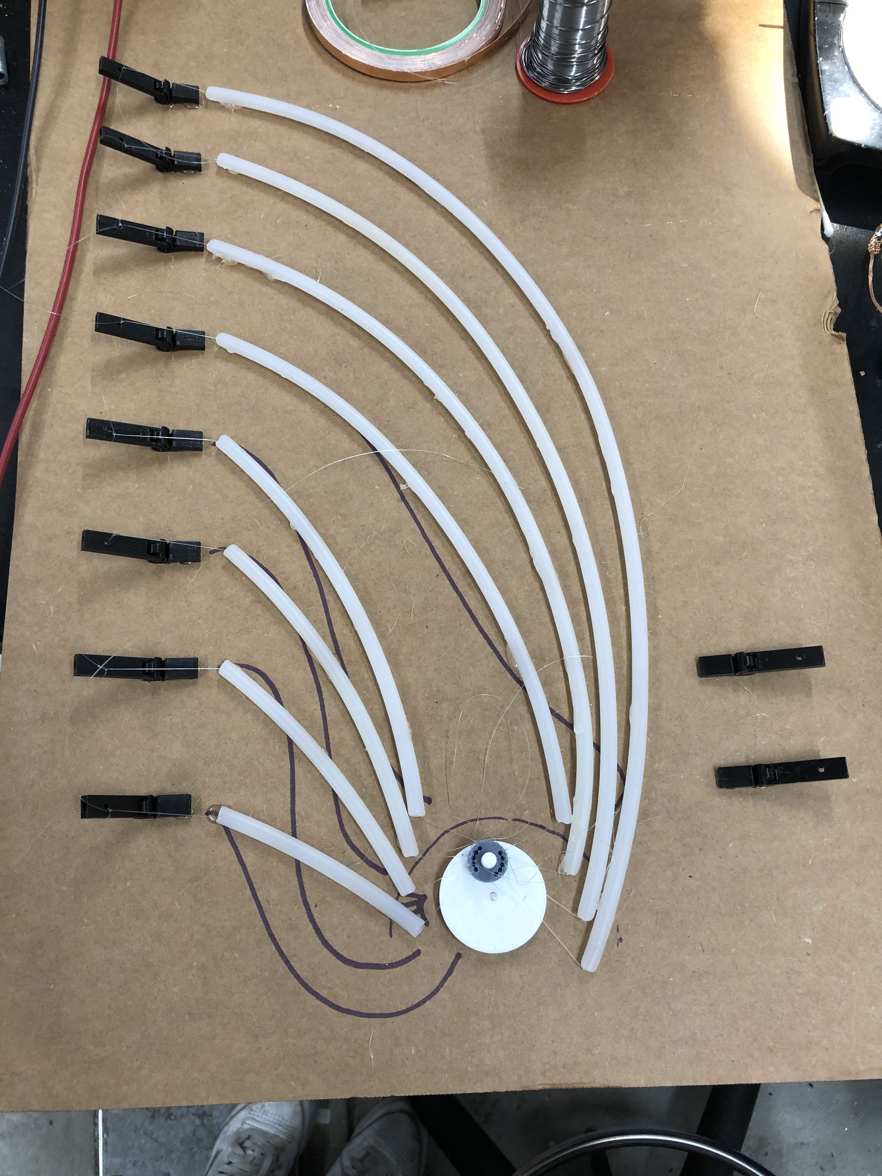
The project is a wearable piece of kinetic art that is custom made to my body. It is a series of “feathers” that move in a wave motion up and down on my chest, and uses strings and motors to create this effect. The project is modular in a sense that every single of the “feathers” that create the wave can be replaced with other objects, such as flowers, animal features, or other designed pieces, as the bendable joint will have a press fit hole that objects can insert into.

Who's done what beforehand?

This project is based on the kinetic crown artist Casey Curran created for the Iris Van Herpen show on July 1st, 2019, titled ‘Hypnosis’, at Élysée Montmartre in Paris. My design will adapt this crown into a chest piece that has interchangeable components that don’t have to be featherlike.

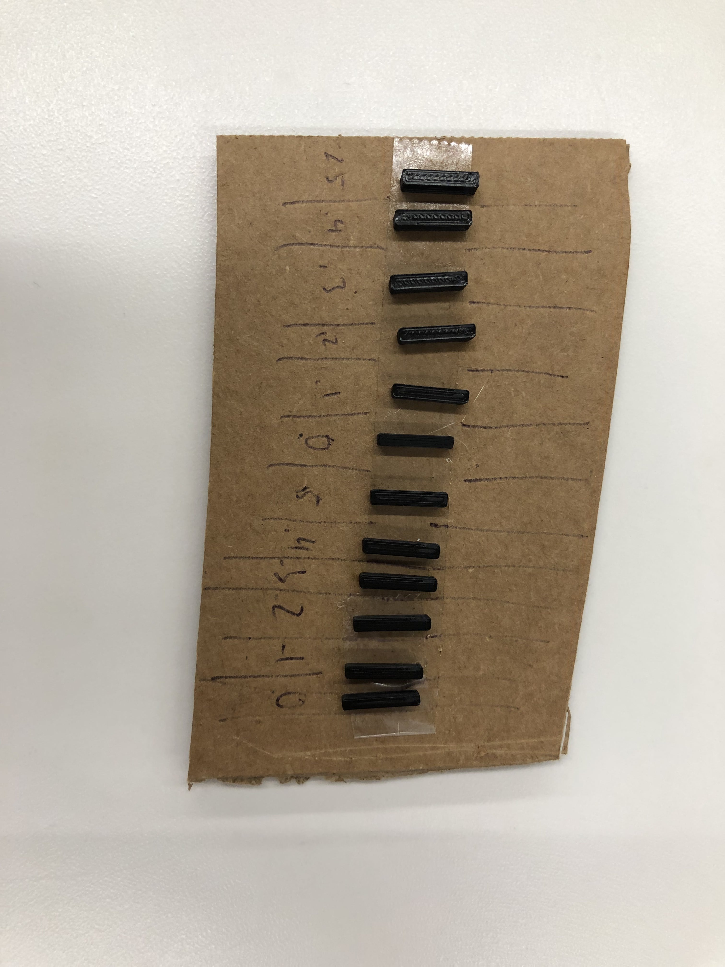
What did you design?

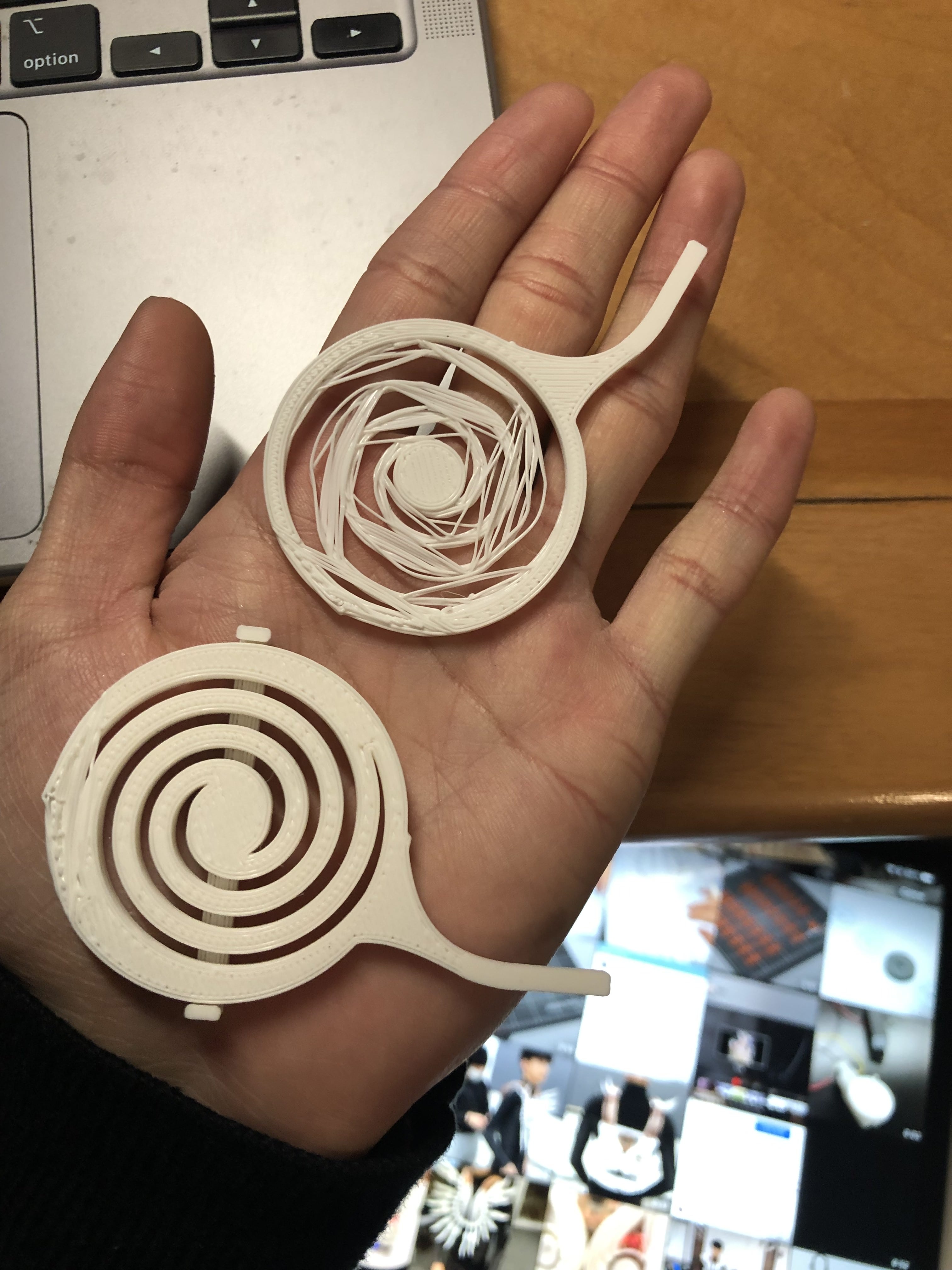
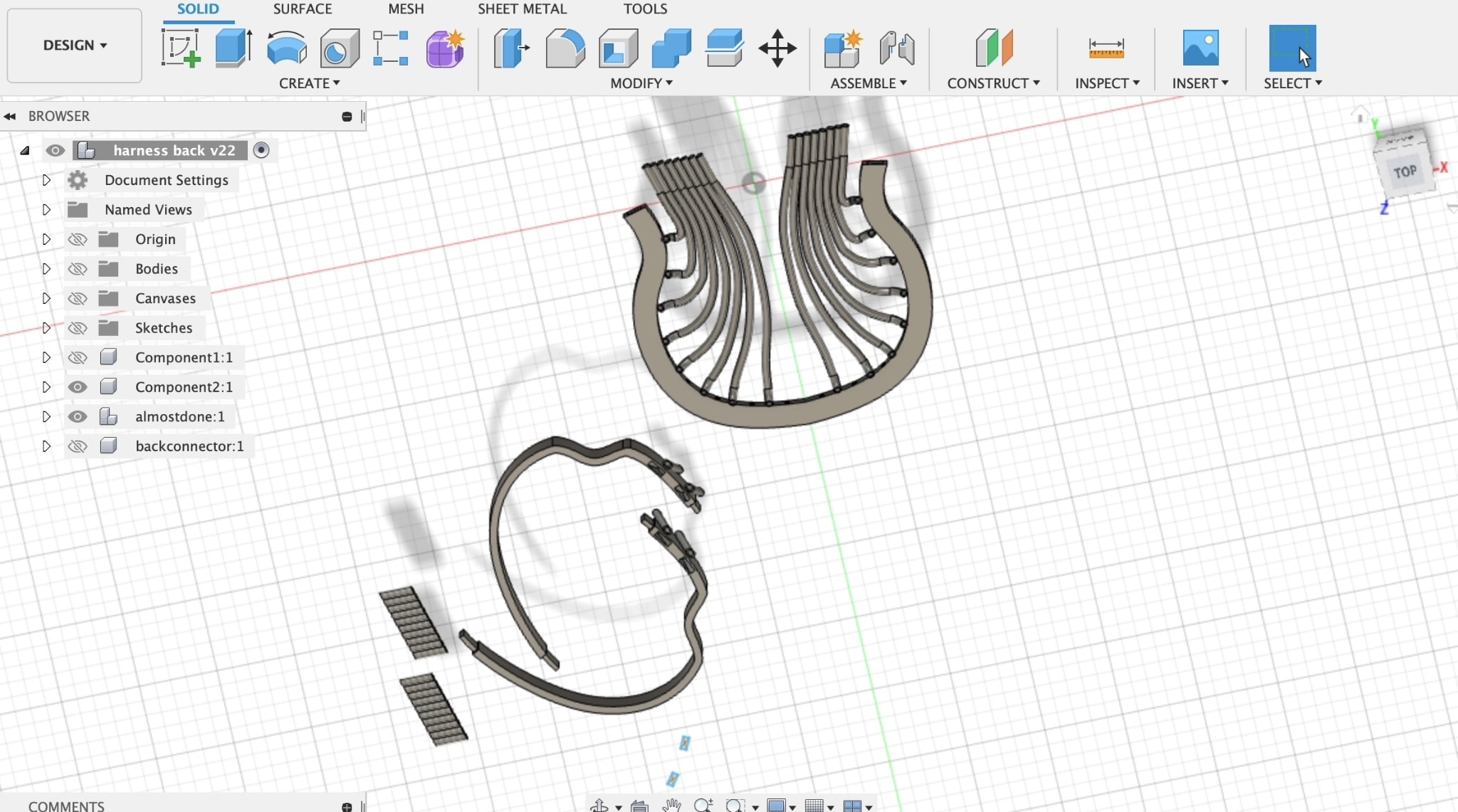
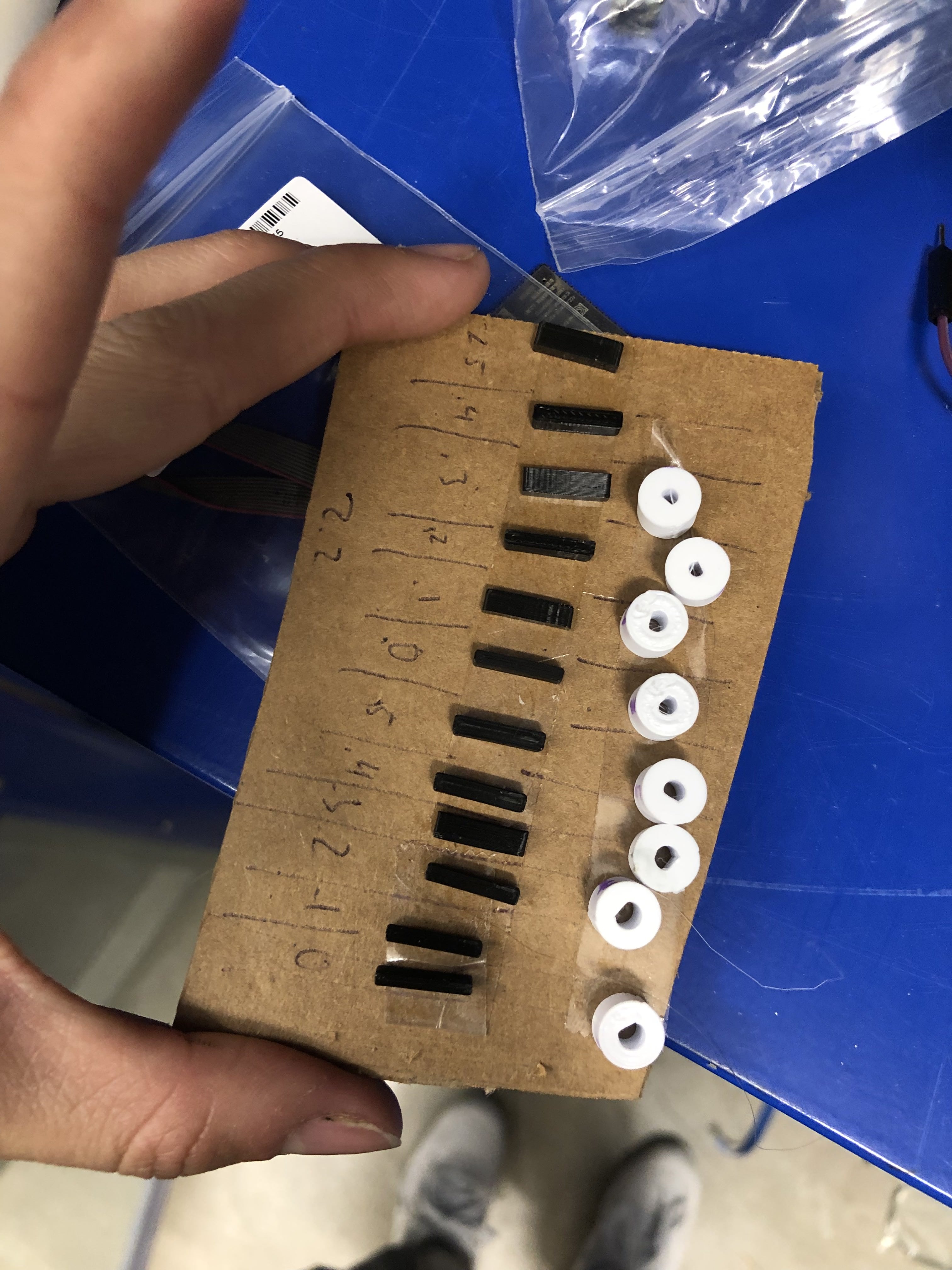
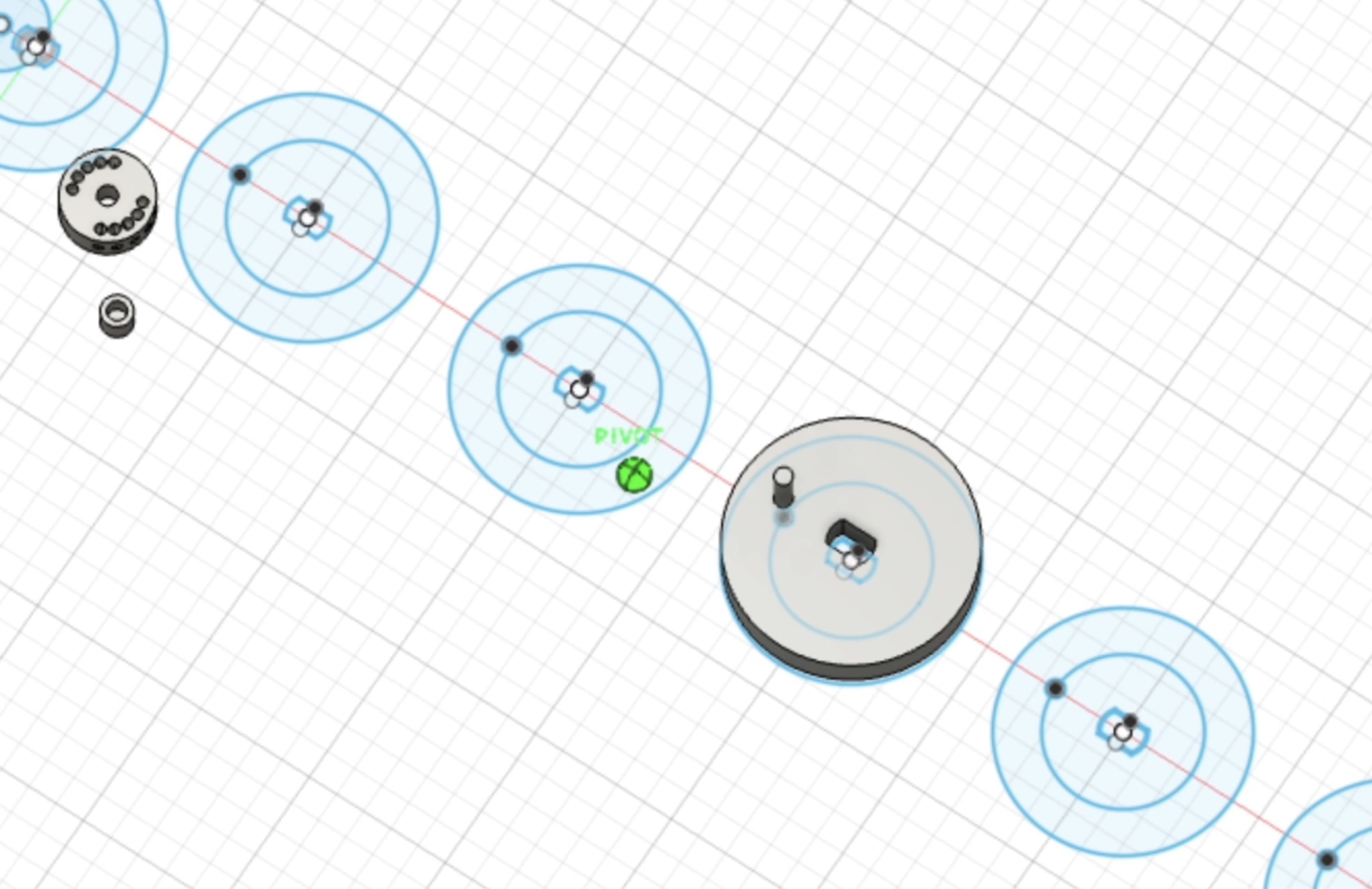
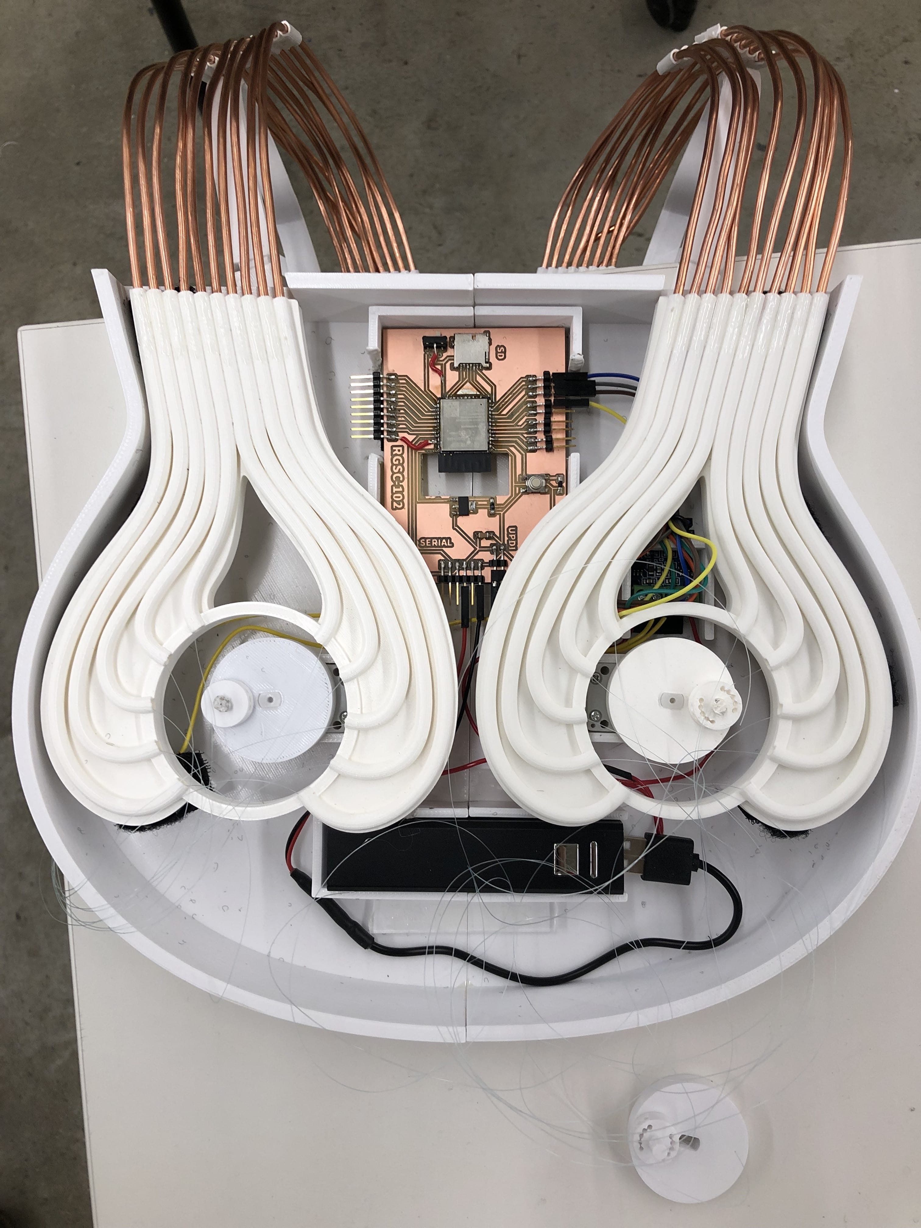
I designed the entire project, but referenced photos and behind the scenes footage of Casey Curran’s original piece. Specifically, I modified torsion joints I found on Thingiverse after designing several springs of my own, and designed the feathers, schematic, packaging, tubing, electronics, and harness. I found ways to differentiate and deviate from the initial sculpture by changing the spring loaded joints and designing a custom body harness for myself to make the project couture clothing, rather than an intricate accessory. The overall movement is pretty similar to the initial design, but I was only using visual references and had to plan all the nitty-gritty components myself.

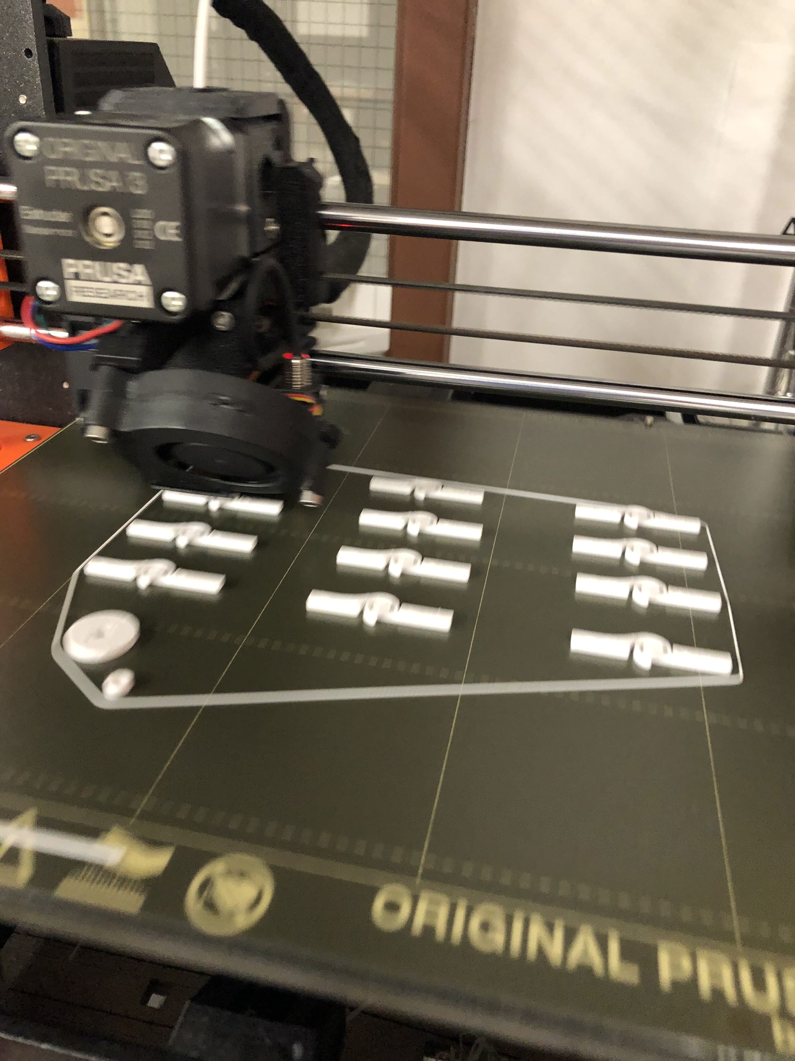
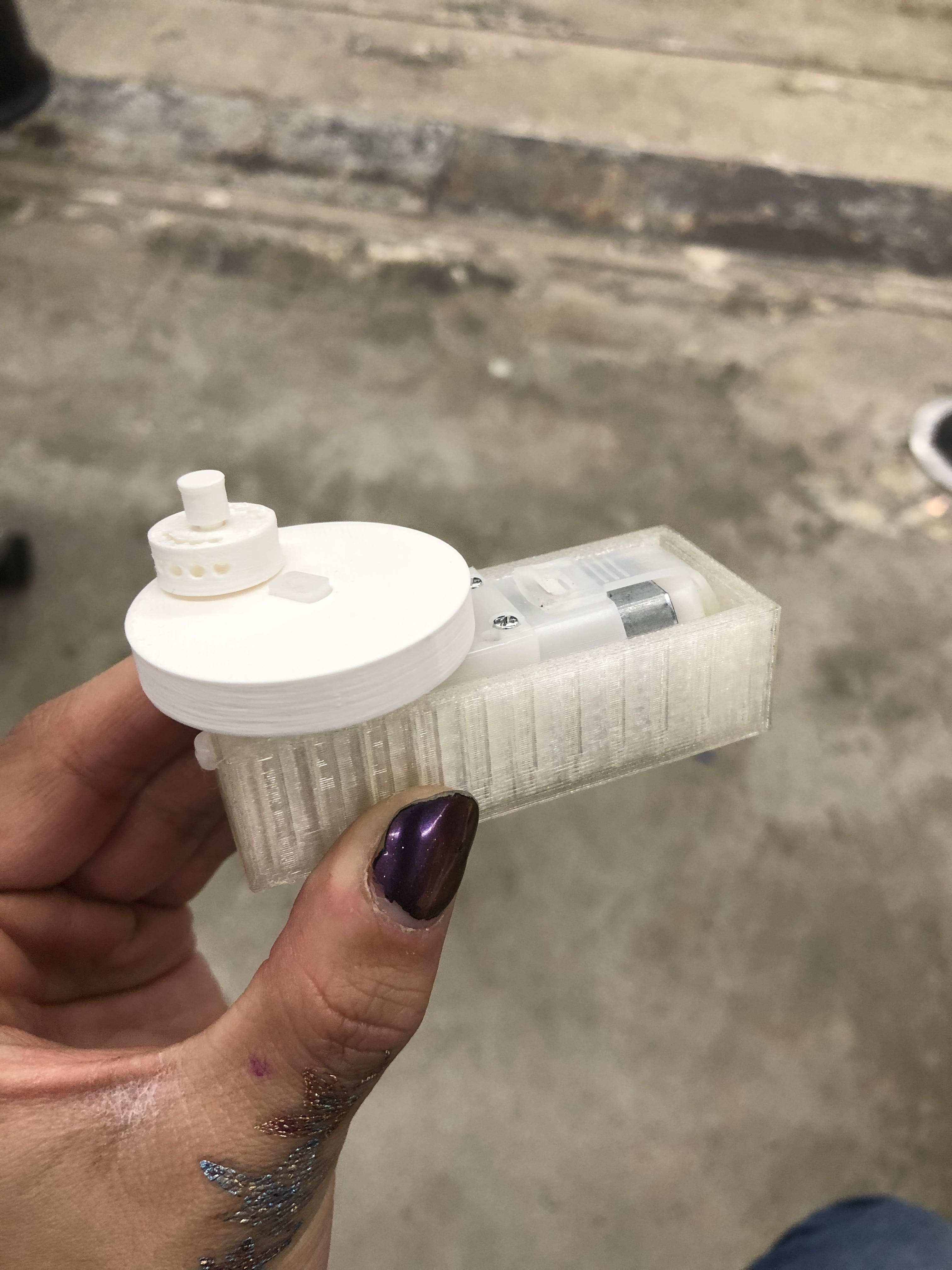
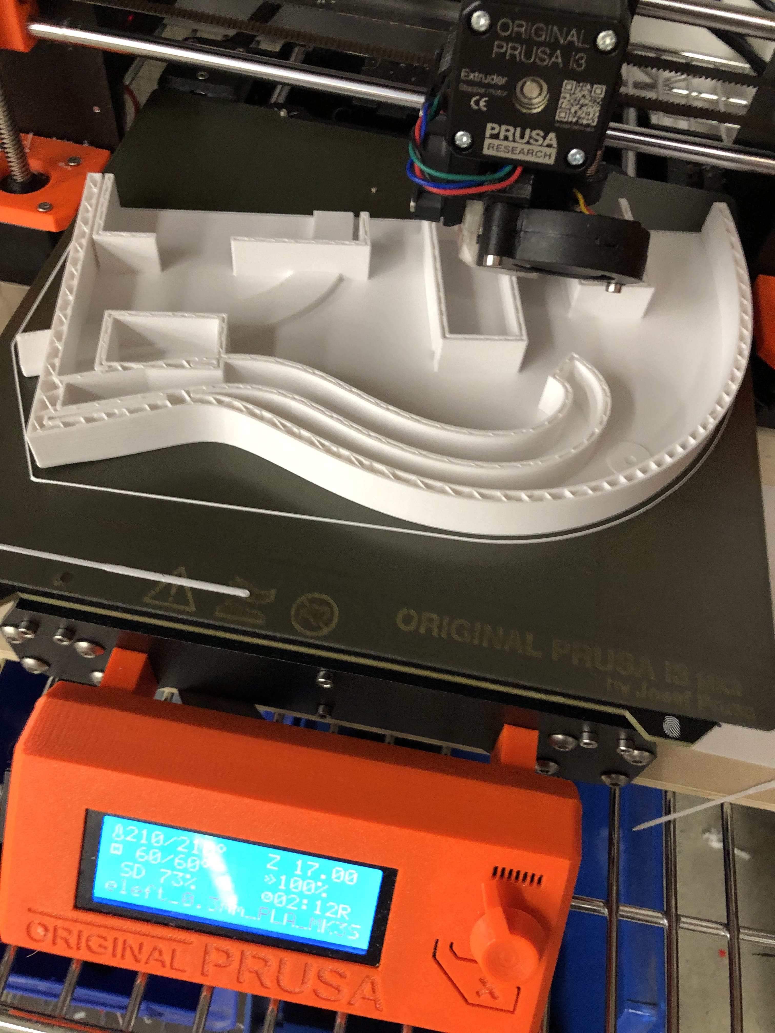
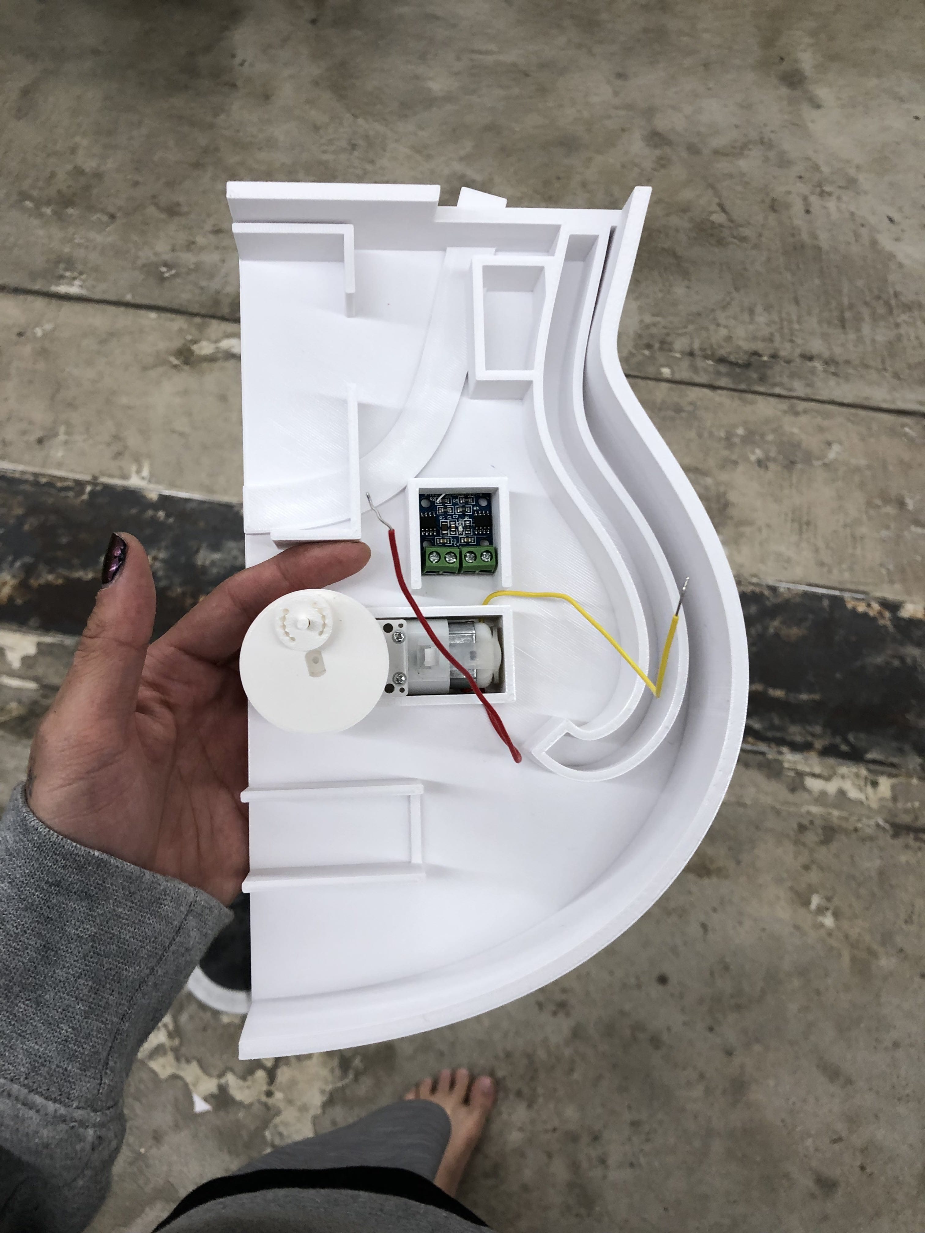
What materials and components were used?

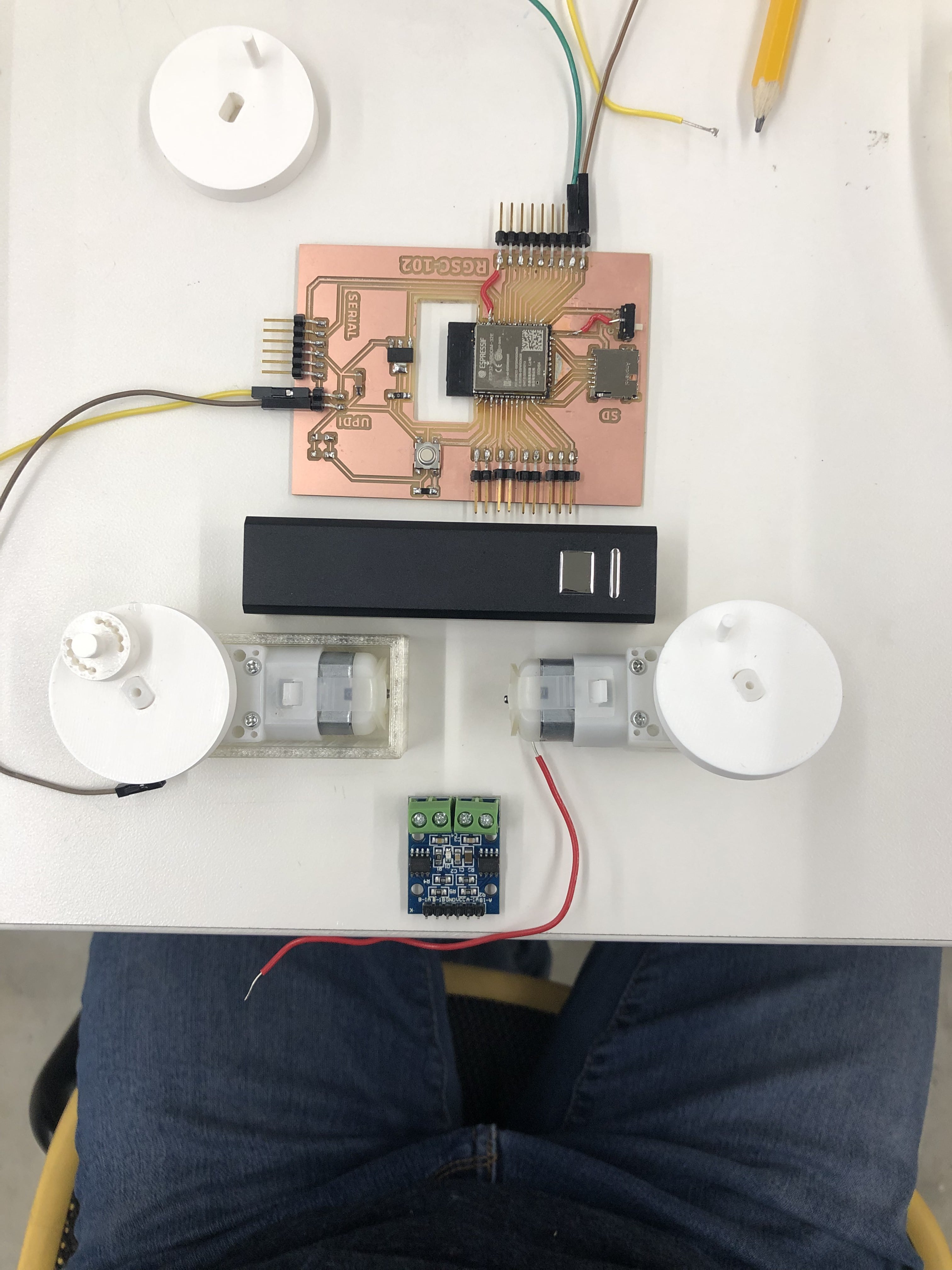
Most of the materials in my project are D printed using PLA filament, but I also used transparent acrylic, copper tubing, DC motors, L9110 motor driver, monofilament string, and electronic components like PCB board, wires, motor drivers, and a rechargeable phone battery.

Where did they come from?

Most of the materials were already in the lab, but I ordered transparent filament(which I ended up not using but lent to the rest of the class), extra superglue, and 32 ft of ⅛” copper tubing from Amazon.

How much did they cost?

The 32 ft of ⅛” copper tubing cost $40, and the PLA transparent filament cost $25. The motors from the lab cost around $6 each(I used 2), phone battery ~$10, and the amount of PLA I used totalled to around 1/2 of a roll of white filament($7.50). I used scrap acrylic and monofilament, and the electronic components were recycled from earlier projects from the class($6 for an ESP32+$3 Motor Driver L9110), so I’m estimating that the total cost of materials was around $80.

What parts and systems were made?

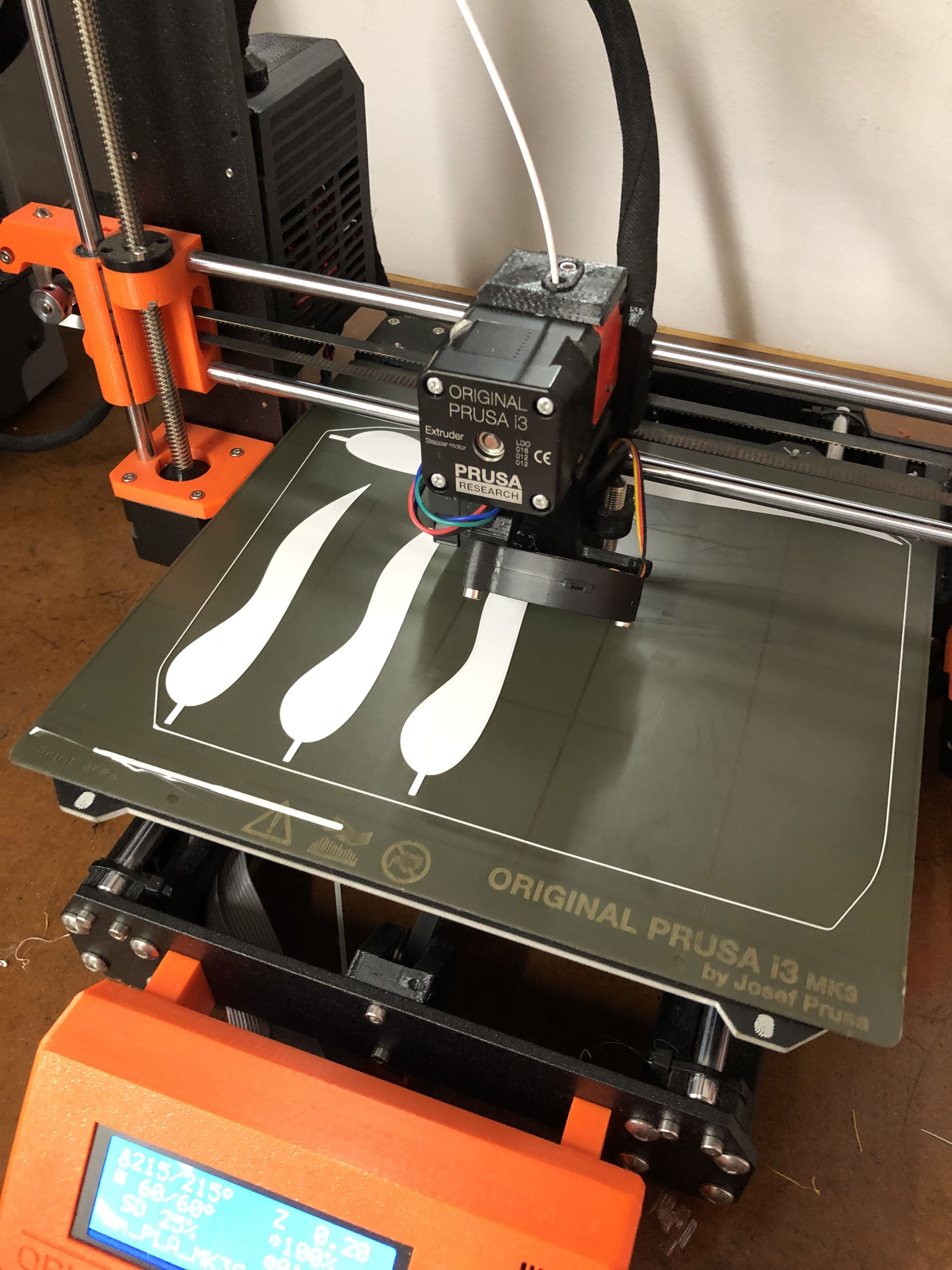
I made joints, a harness, tubing, feathers, packaging, and the mechanical movement with 3D printing. Some electronic components were made by milling an ESP32 board.

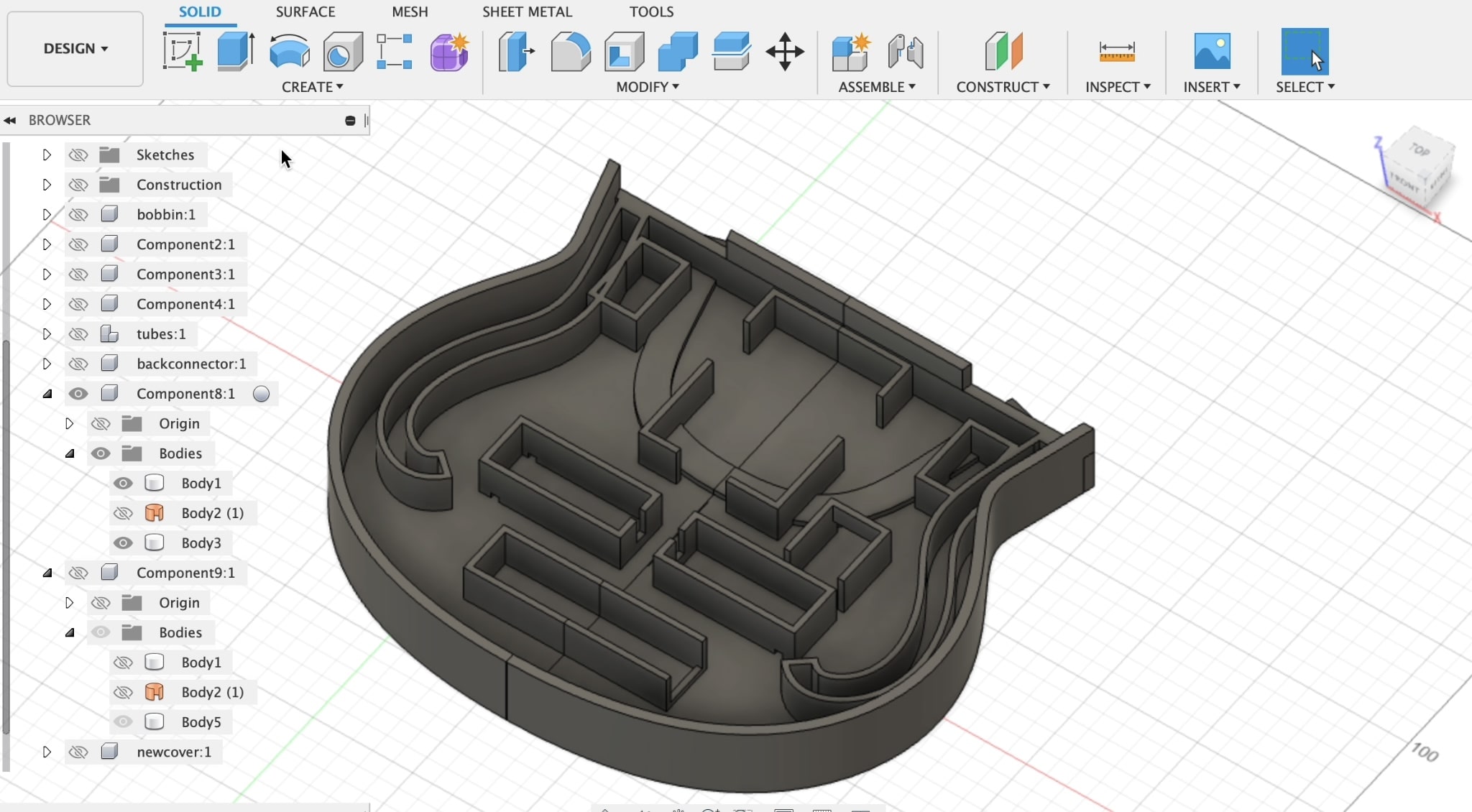
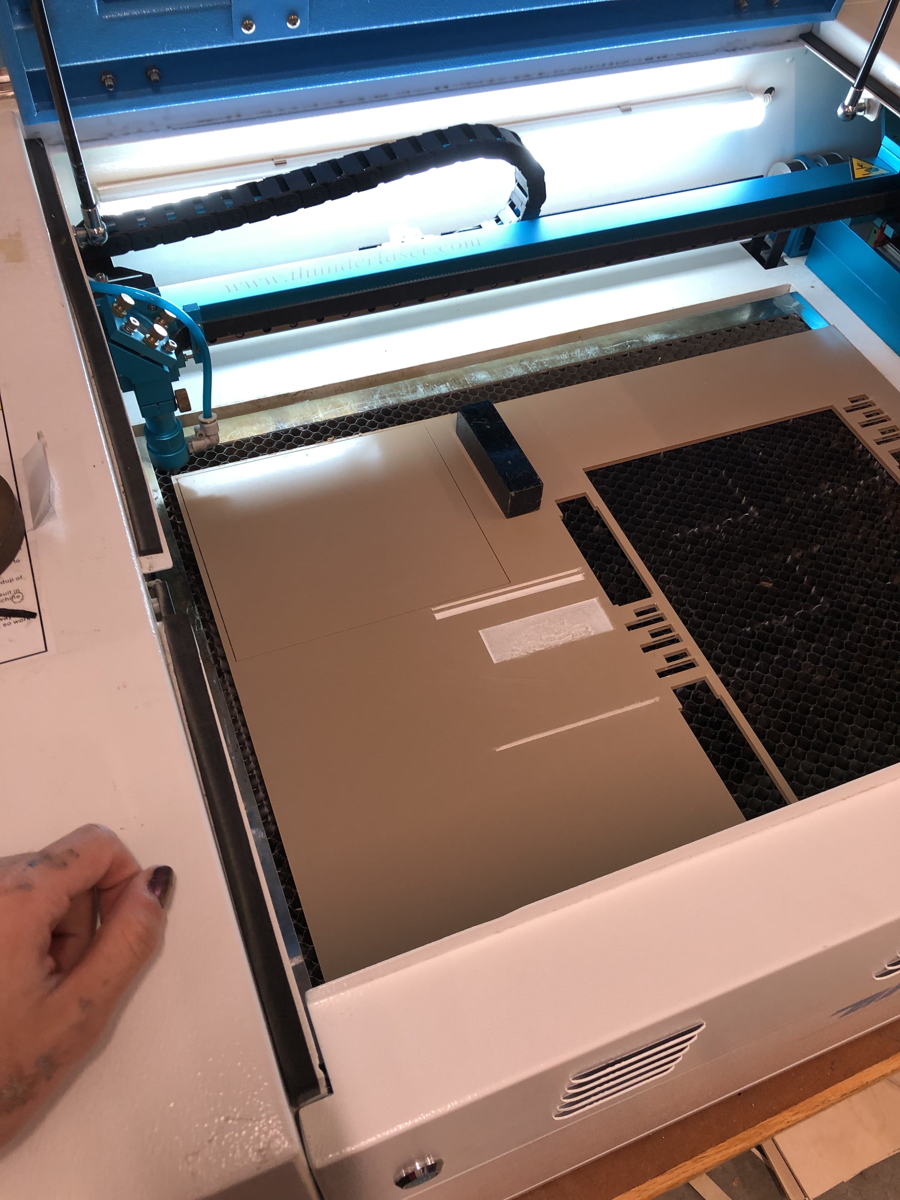
What processes were used?

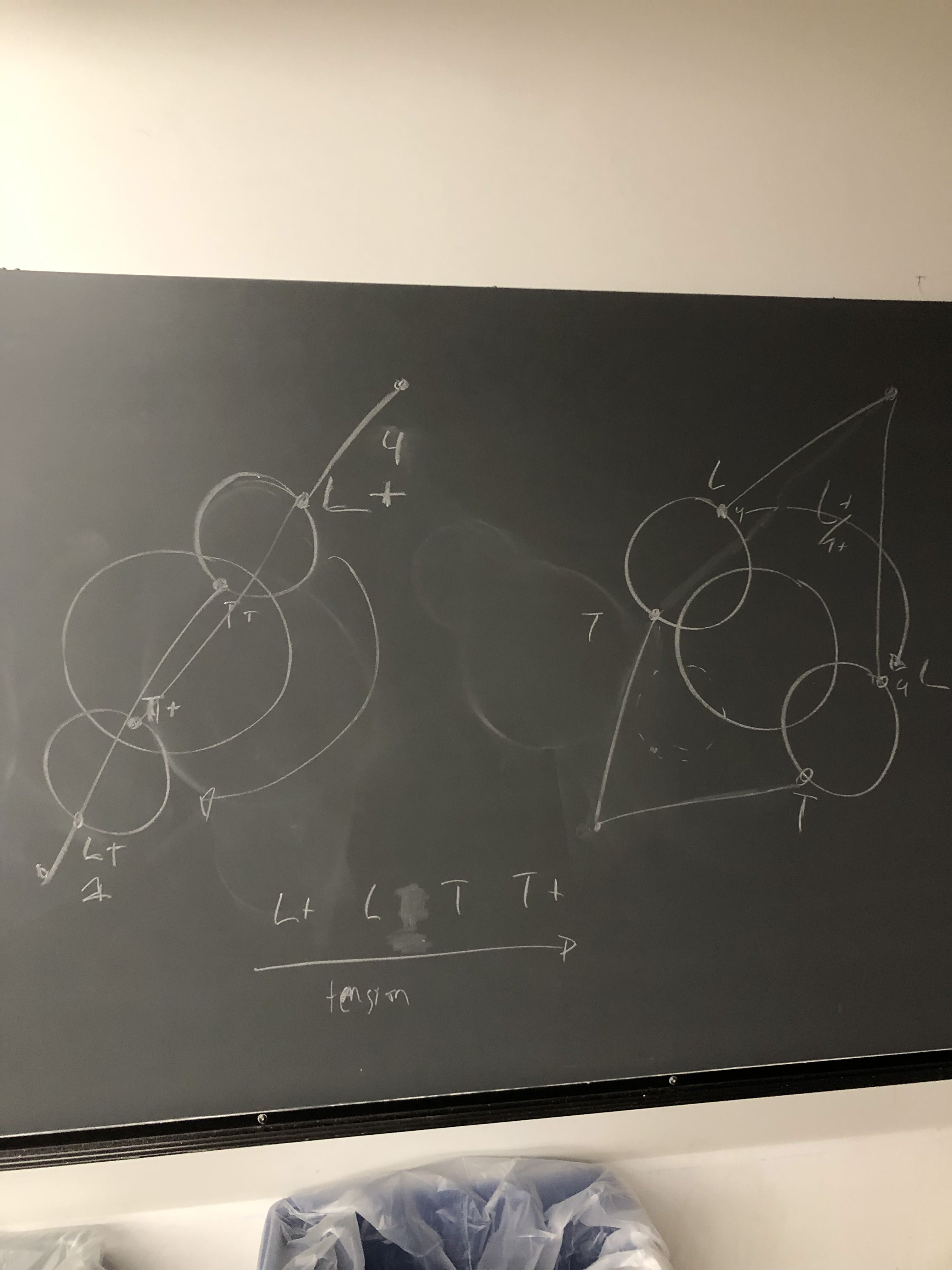
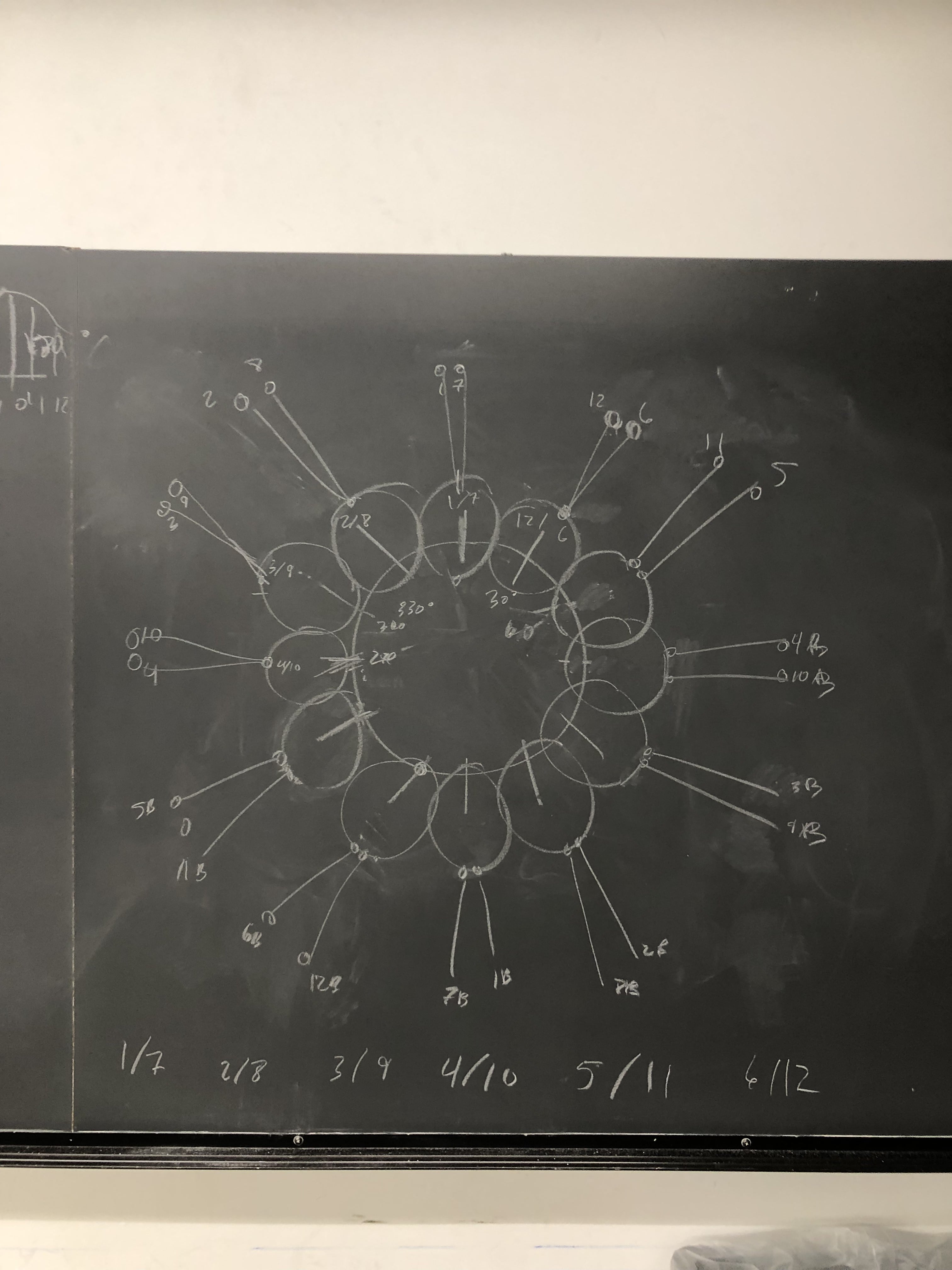
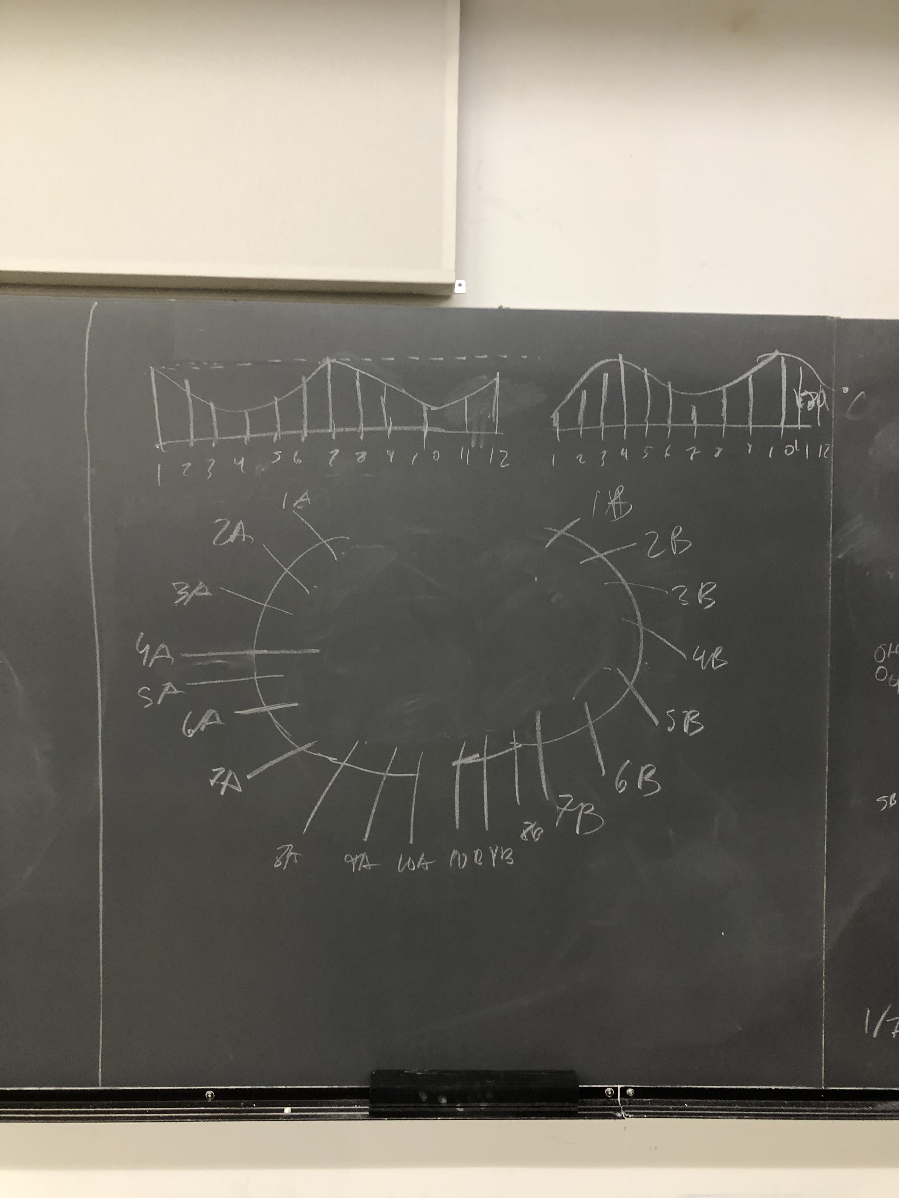
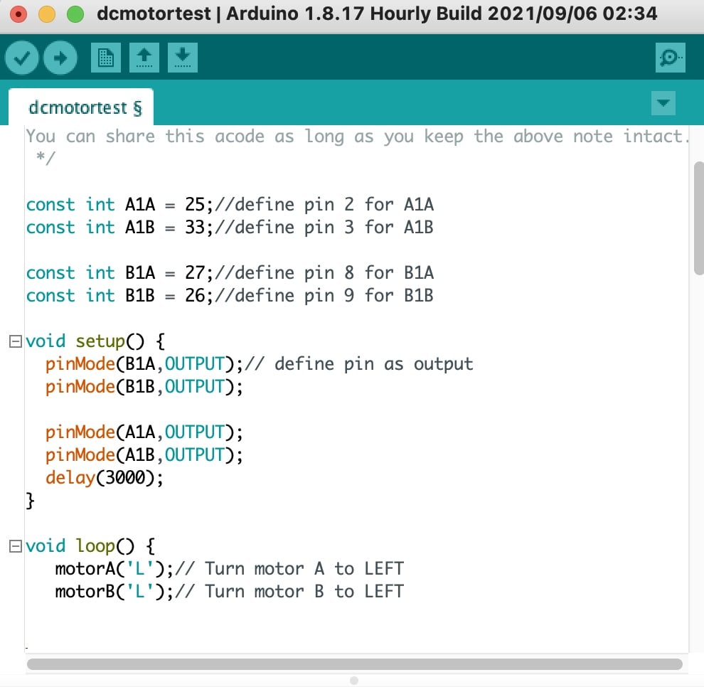
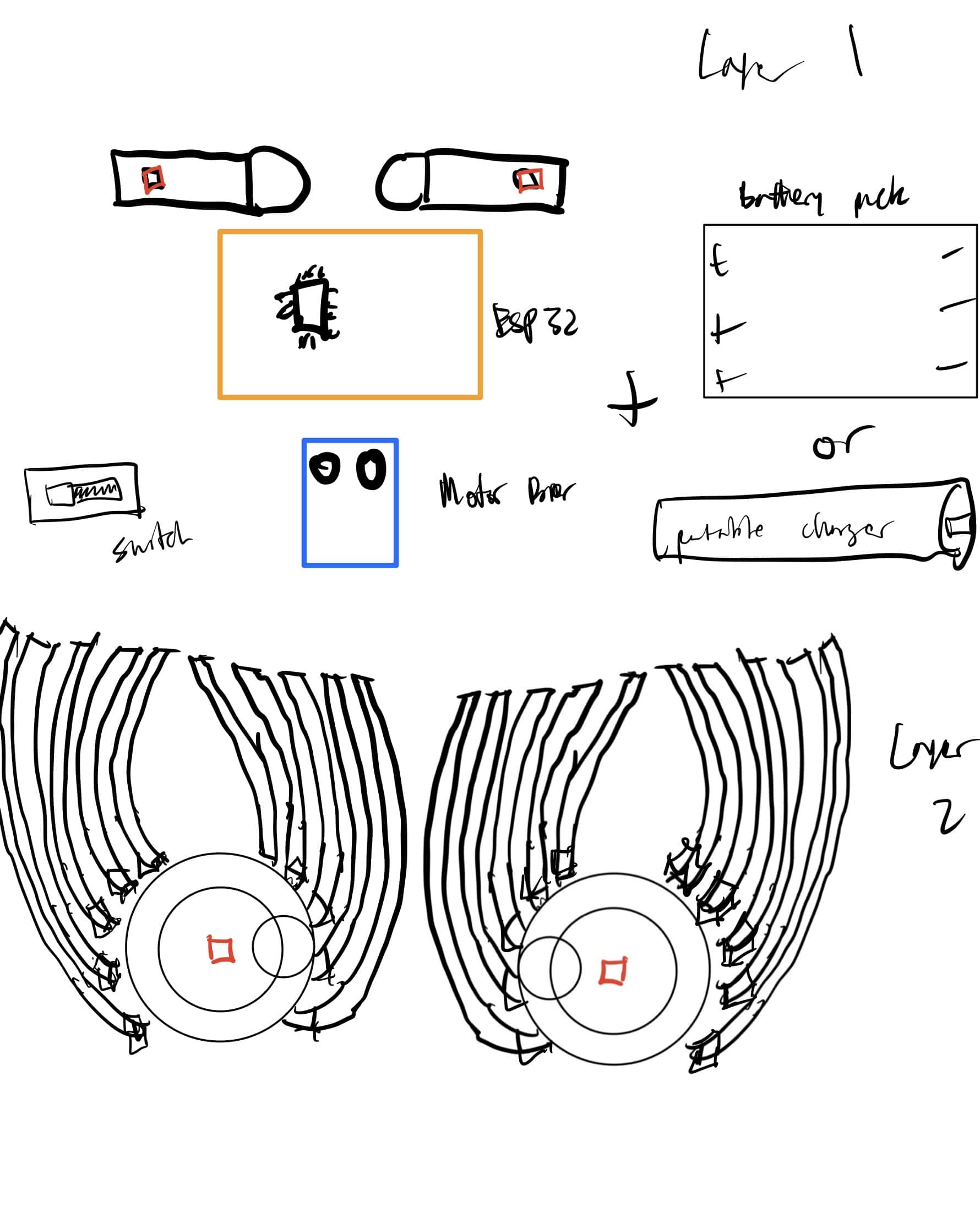
2D and 3D design was used to design this entire project with either CAD software like Fusion360 or chalkboard ideation to plan the schematics of the extremely complicated mechanical movement. I used subtractive fabrication processes to laser cut transparent acrylic and mill a PCB board. Electronics design and production was used to create the ESP32 board, and embedded microcontroller programming was used to program the 2 DC motor rotations. System integration and packing were used to create the arrangement of the electronics on a back piece, as well as fitting the whole project custom to my body.

What questions were answered?

Can I create haute couture using modern fabrication techniques? Yes!

What worked? What didn't?

The wave motion stayed pretty consistent throughout the presentation day, but one of the strings eventually snapped. This is ok since I could easily replace it, but I plan on replacing it with a stronger filament. Other than that, everything seemed to work!

How was it evaluated?

Since my project had a simple premise but complicated design, I evaluated it based on its functionality(whether or not the motion worked, quality of motion, number of features), and aesthetics(symmetry, detailed appearance, neatness). I think I succeeded overall, but the wave motion could be calibrated in closer detail, as some of the feathers have larger ranges of motion than others, and some fell prey to too much friction within the copper tubing. In the future, I would also add more capabilities if given more time, such as the ability to adjust the speed of the wave, and also make it easier to put on/take off. Aesthetically, I thought it looked amazing, but I would still like to add some stationary feathers to decorate it further, and also make the feathers more symmetric within the motion. I also think that if given more time the assembly should be done in a neater and cleaner way.

What are the implications?

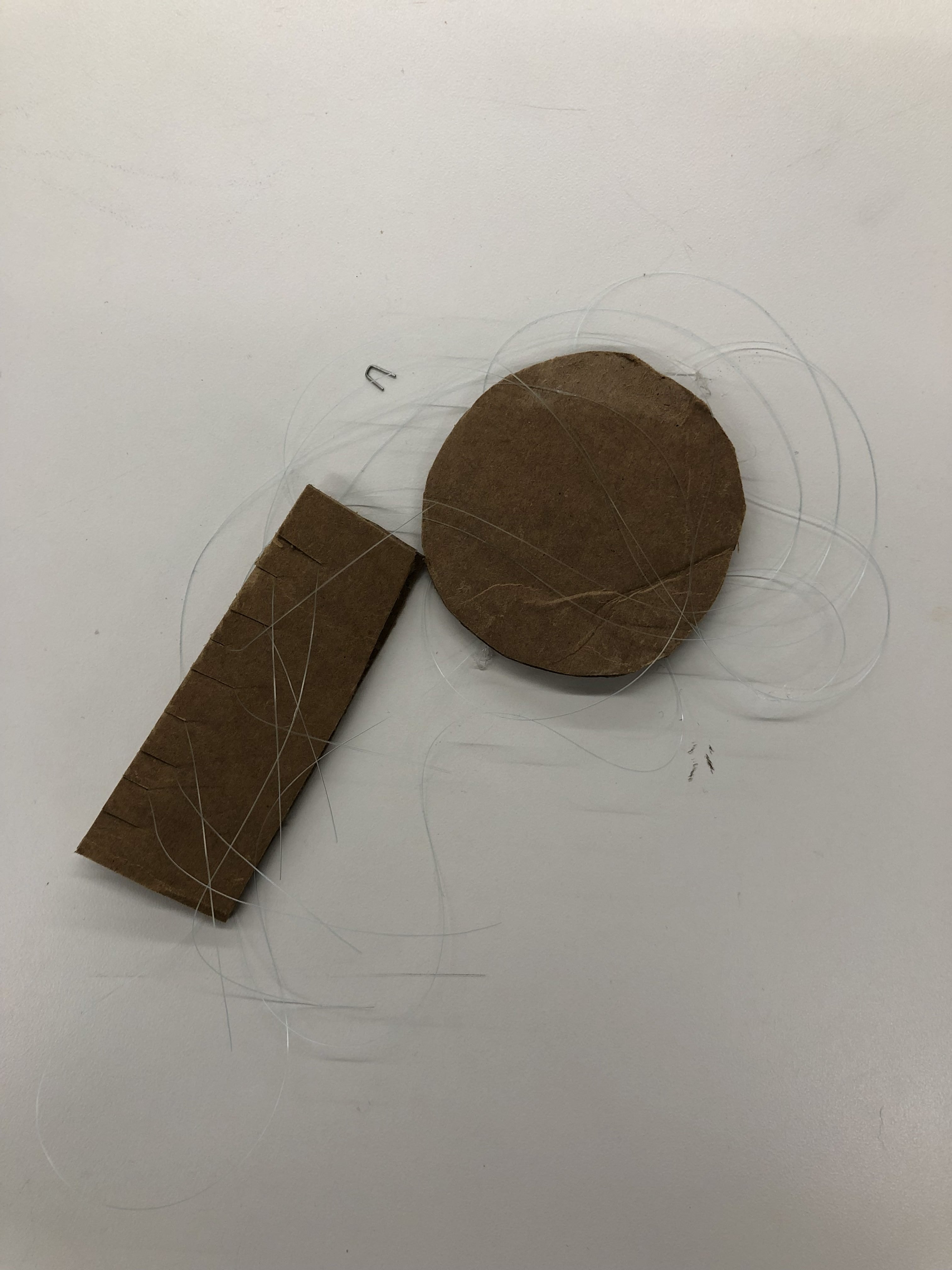
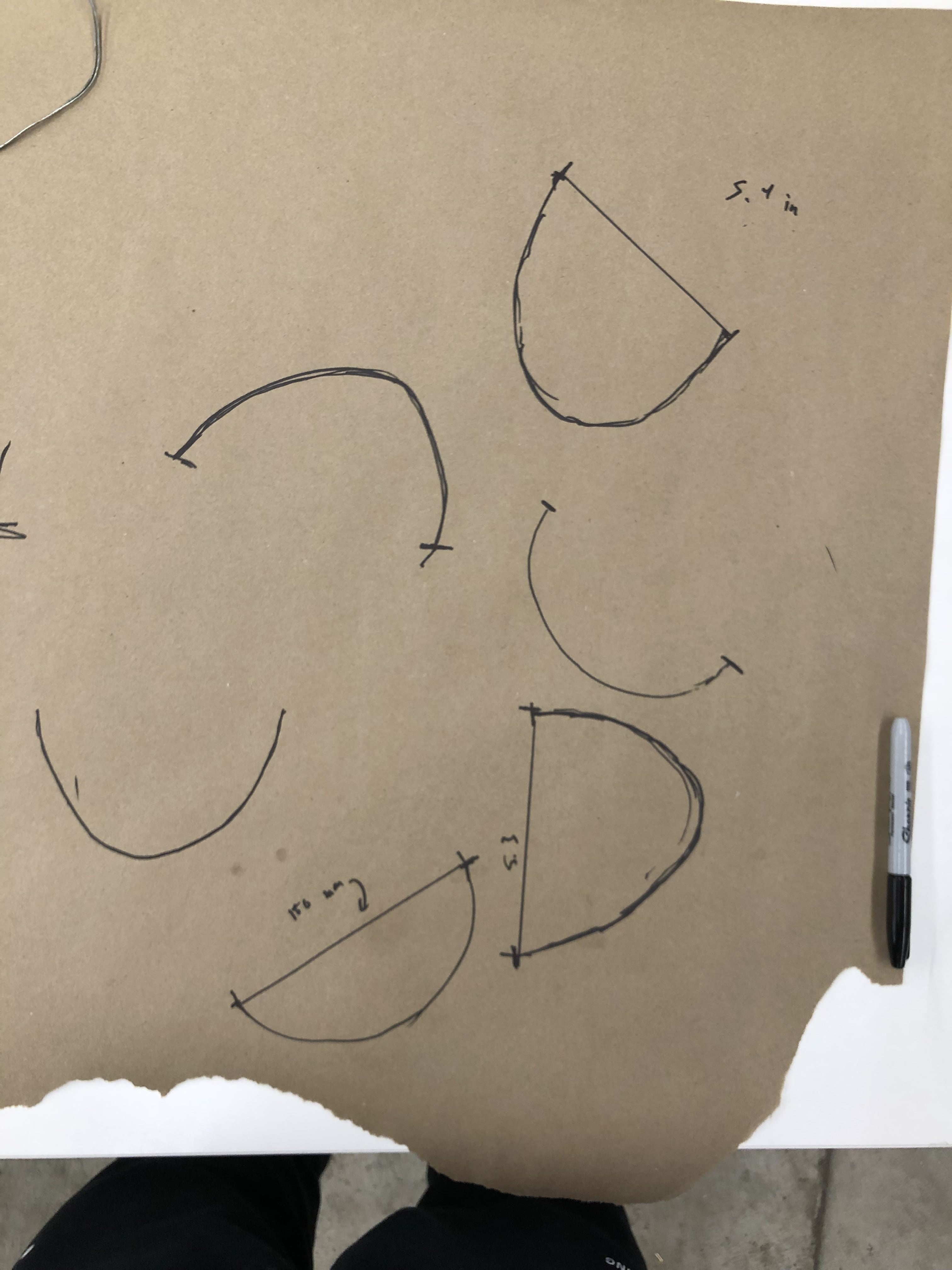
The implications of my project prove that high couture involving electronics and mechanical parts are possible to fabricate by oneself. Haute couture, specifically involving electronic components, is currently seen as a process that is very far out of reach for normal individuals to produce or even procure, so I was very proud of myself for being able to produce something that was not only functional but aesthetically beautiful. I also learned that creating things and testing them out tangibly was a lot more productive than diving deep into a hole of math and precise measurements to fabricate complicated machines. I wasted a lot of time ideating and worrying about the nitty gritty details of the mechanics that were very hypothetical, but ended up realizing that some things could be planned better and quicker simply by making them physically and adjusting them to a final result. I learned so much more by creating a 2D physical mockup of the kinetic aspects of my project than staring at a chalkboard all day. Another application of this lesson was learned by making many different versions of my designs physically to prove their functionality, such as the press fit joints, packaging, and tubing. Rather than making detailed CAD models of each of these aspects in the hopes that they can be printed accurately and precisely to function, keeping my expectations low and just printing things and toying around with them sped up the process of design and fabrication.