Final Project: A notebook
The brief is pretty broad, but the summary that seems most apt is this: make something that does something
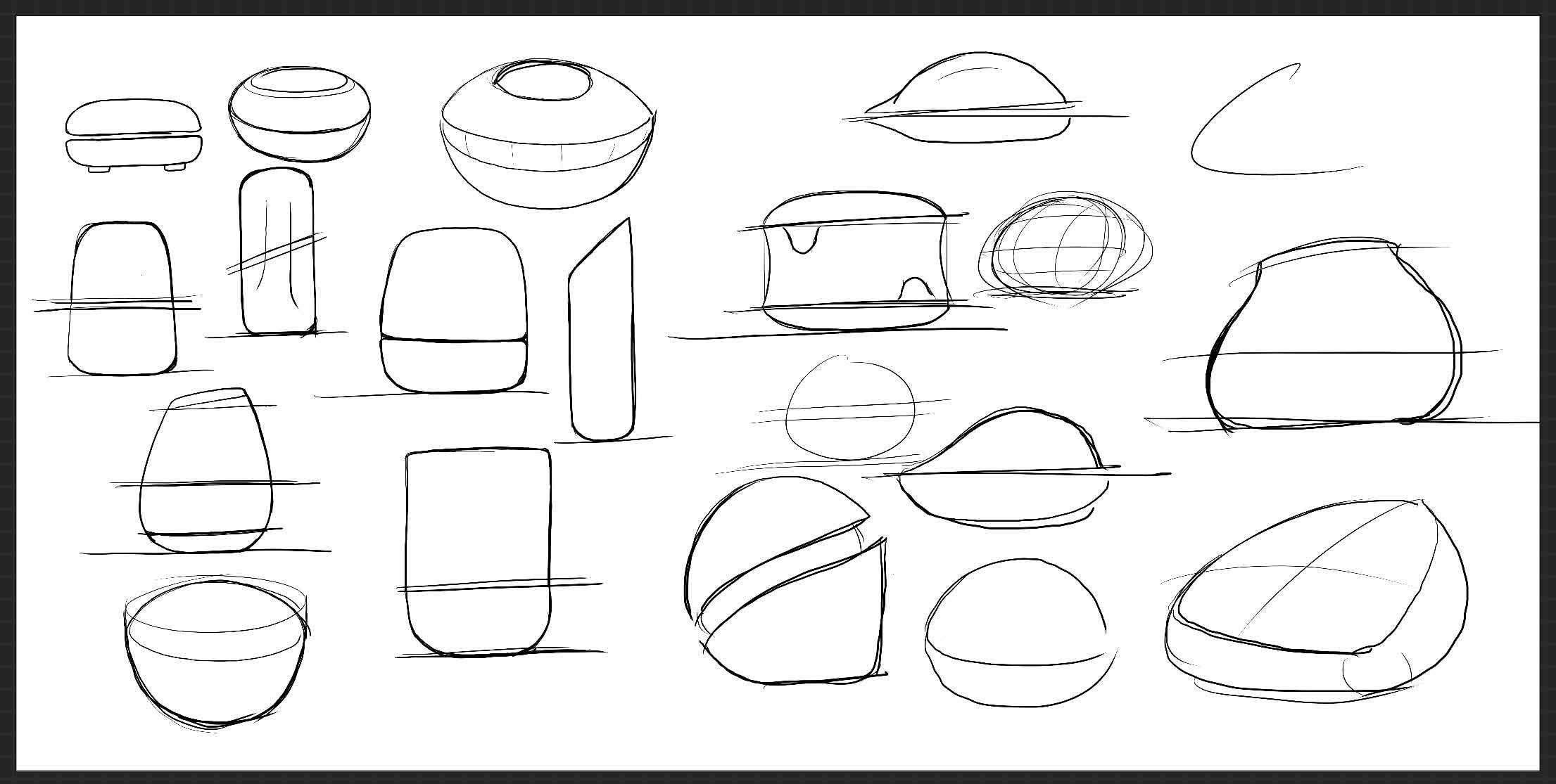
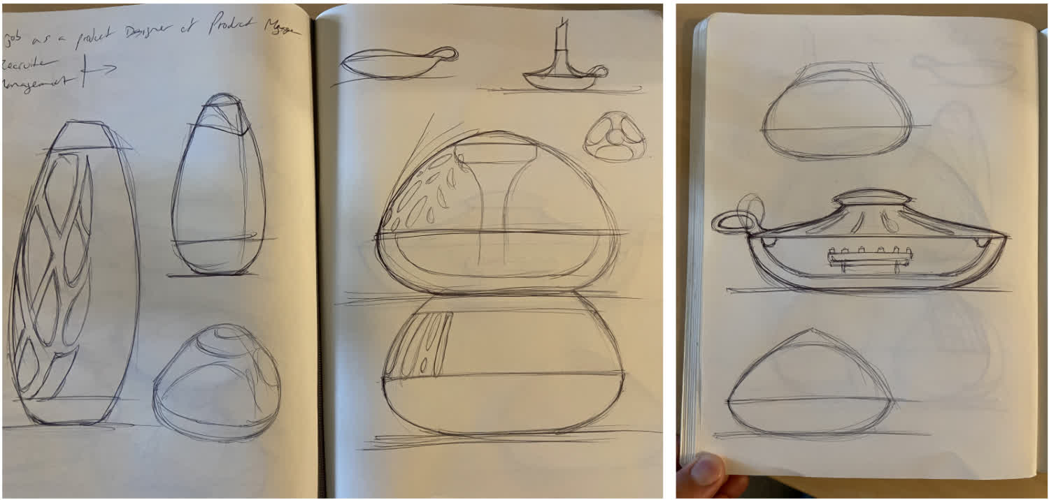
Oct 14: Project Pivot. Sketching out a new Concept
My original idea, an automated chladni plate, didn't really take. I decided I wanted to make something that would have some application in my daily life. So I went back to the drawing board. I was hitting a wall for a while, but as I was sitting in my windowless garage working on the Clank machine, I realized I wanted to check what the weather was like outside. And then I though, hey, what if I had a device that communicated in some way that it was bright or dark outside. Something that wasn't an app on my phone but an external interface. And I thought a lamp could be a cool, simple, somewhat analogous interface for communicating that information. So I started sketching.
Open Questions:
I have a handle on how to make the physical forms. Some of that may be ambitious given the timeline, but it's doable, and I can adjust my goals based on shop availability over the next few weeks.
The bigger questions for me, though, are the actual electronics I should use. Here's what I am thinking so far. Broken into "need to have" and "nice to have:"
Need to Have:
Power: This could be a batter or a cord plug in. I'm leaning towards a 9v barrel jack to keep things simple
On/Off Switch: My initial impulse for this is to use a magnetic switch of some kind, but I am open. Considering I will not be manually adjusting brightness, the switch really is just and on/off discrete input.
Input Device: This is an open question. I'm considering a phototransistor to read the brightness of the outside, but I am also considering linking the brightness to a data source that tells it where the sun is in the sky. If I go that route, I'll need wifi, which may require a chip other than the ATtiny1614. Maybe the 3216 for more storage.
Nice to Have:
ESP to enable me to turn the lamp on with my phone
Capacitive sensing
Nov 6: Physical Prototyping
Once I had a simple CAD, I wanted to print the components to test the fit and get a sense for size and proportion. Because the Sindoh printers were busy when I went into the shop, I sent my files to Shah to run the ABS printer. Here are the results:
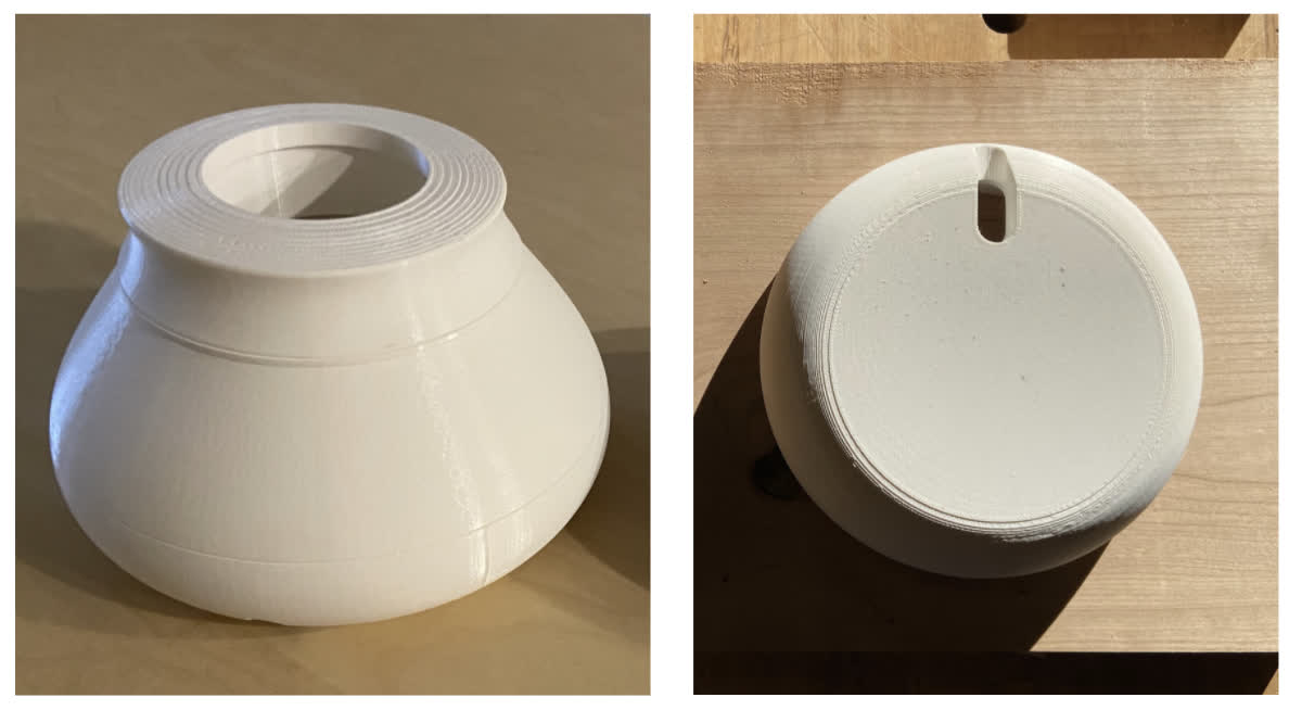
I liked the size and the proportions of the prototype, and the components fit well together, so the tolerances were correct. That said--and I should have foreseen this--the light only shining through the top aperture doesn't really provide a whole lot of ambient light. So I think the center componenet should be translucent to give more opportunity for the light to escape. A change of the component design and material is in order.
Nov 10: Version 2
Back to the drawing board to create a more ambient lighting design. Thinking I'll use CNC milling with wood and 3D printing for the middle section as well as the internal components.
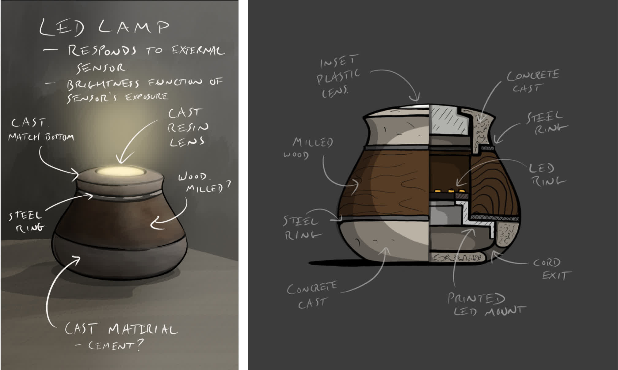
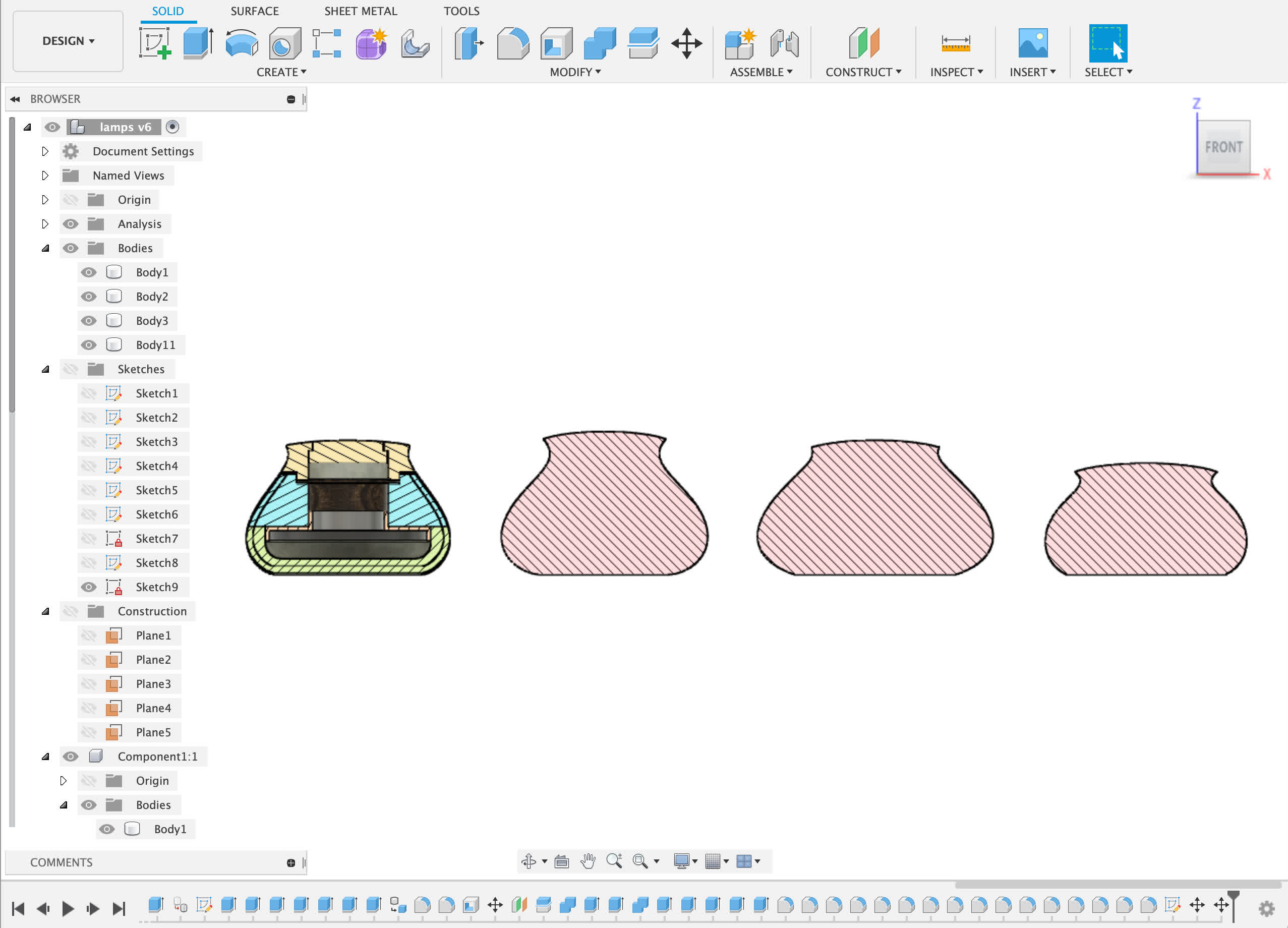
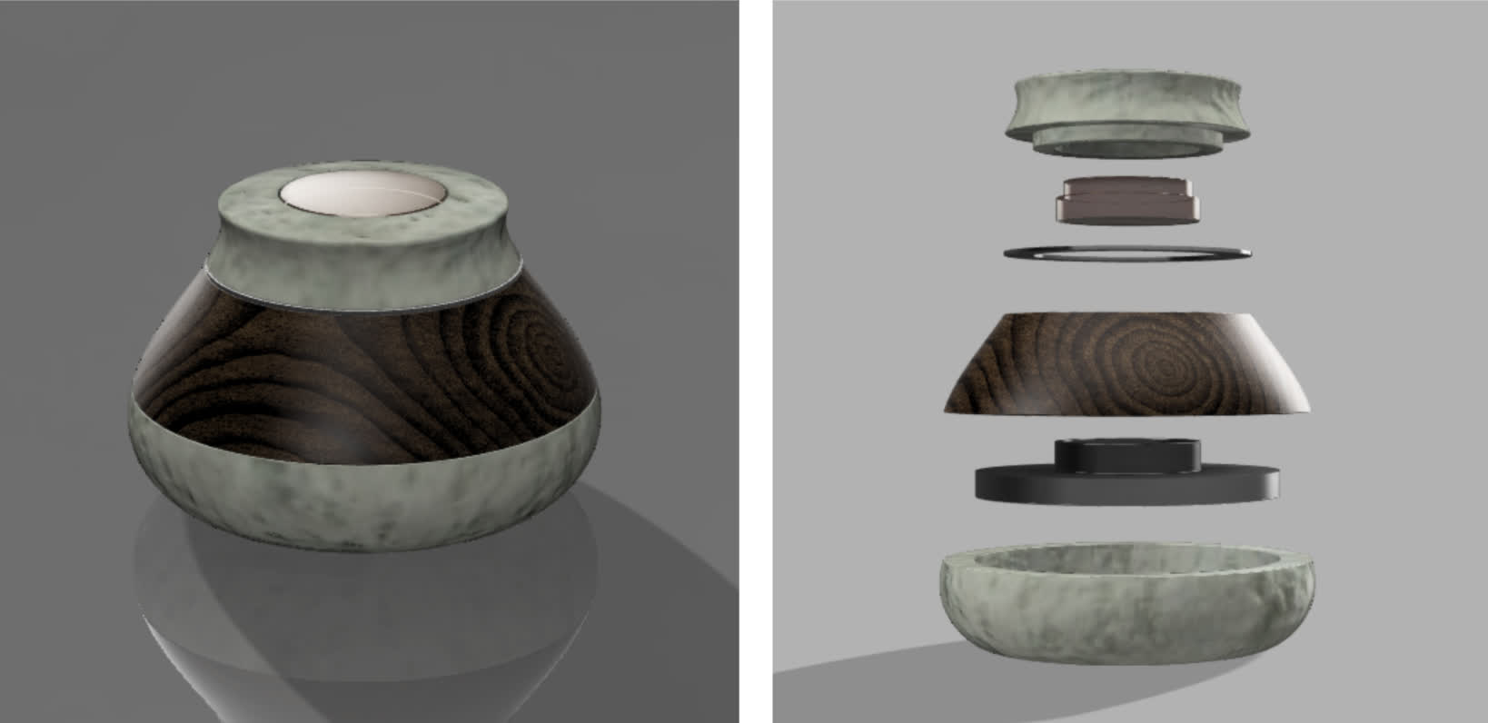
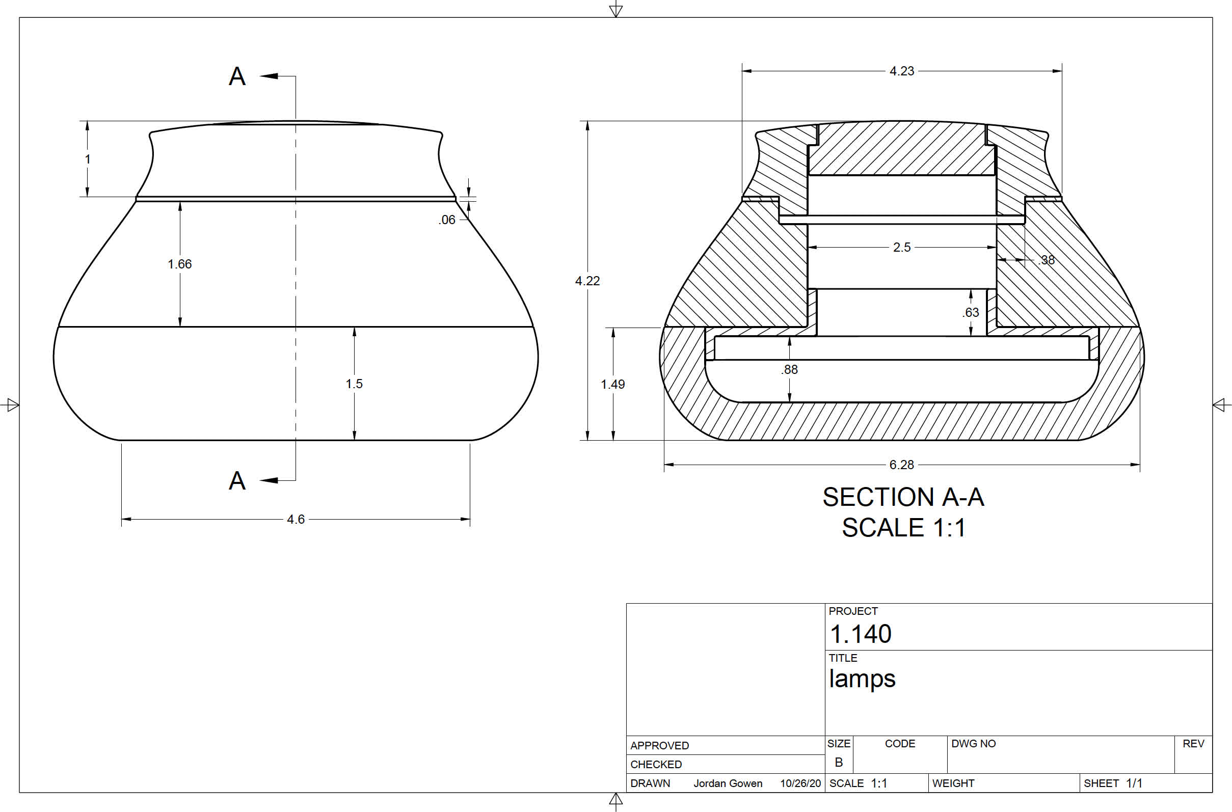
Sketching and CAD:
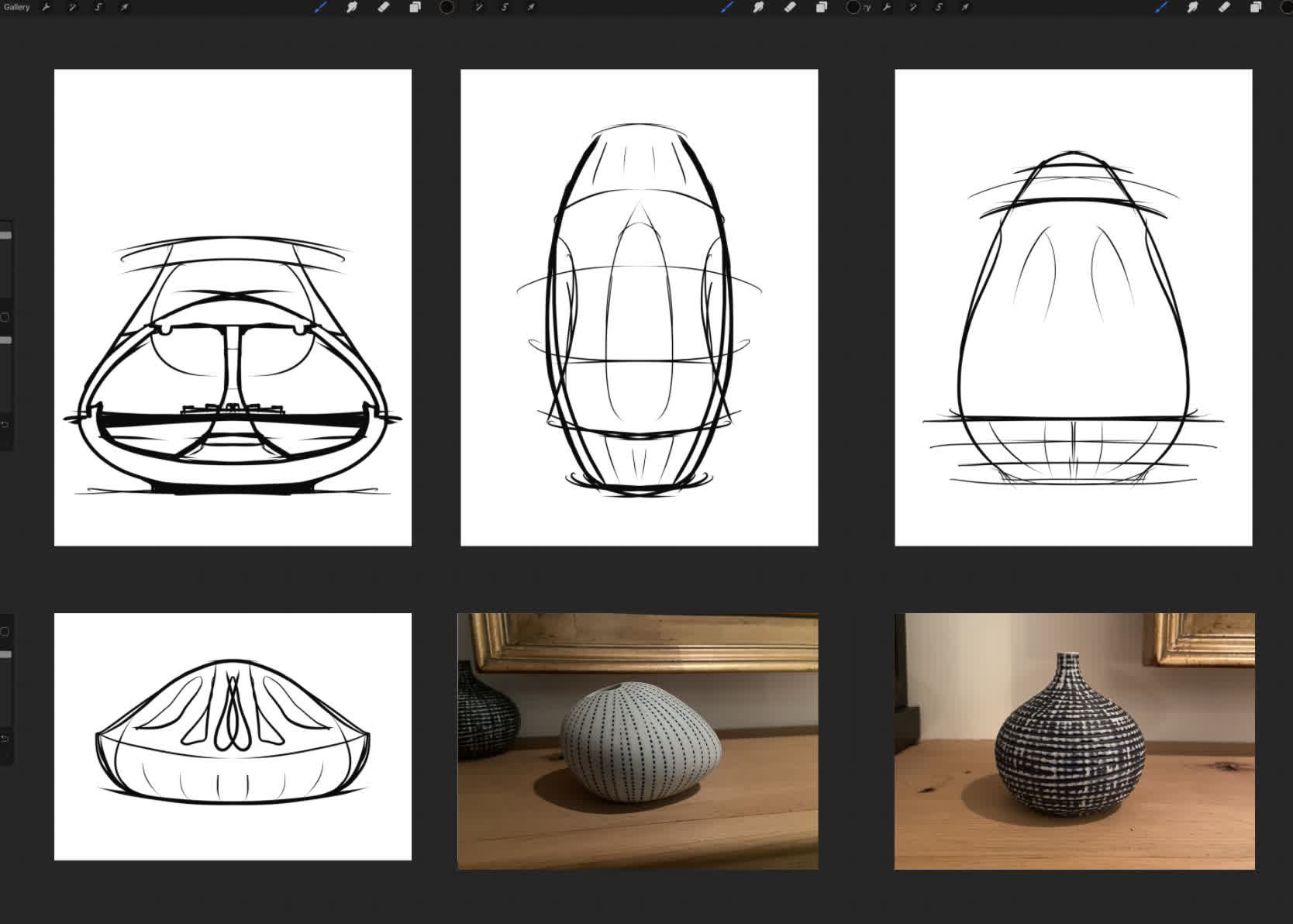
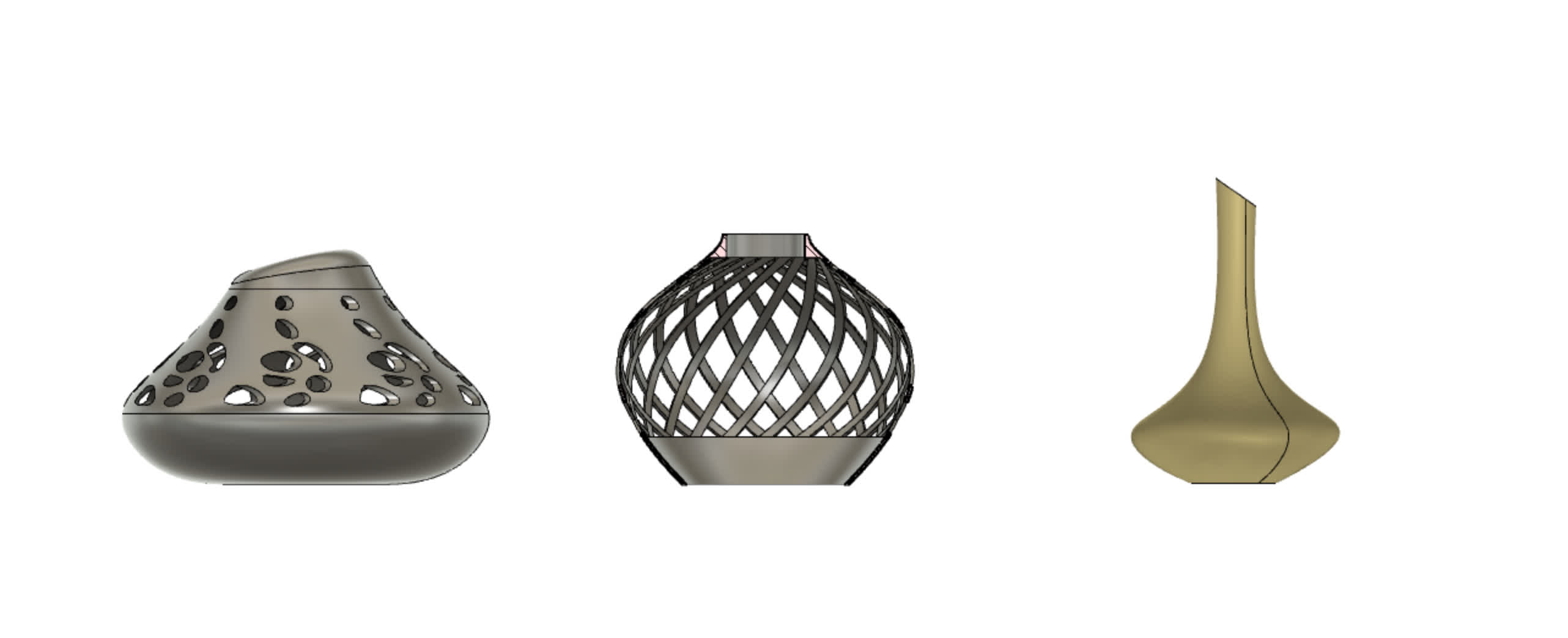
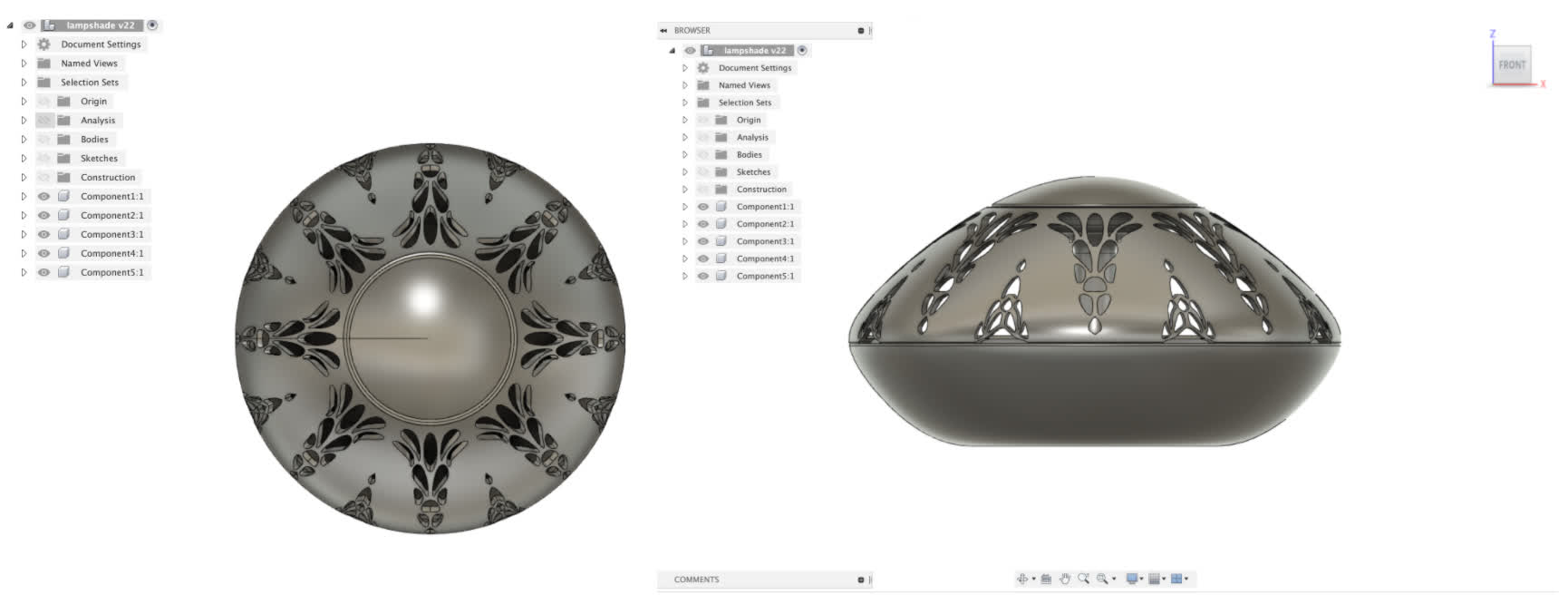
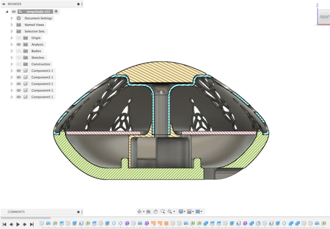
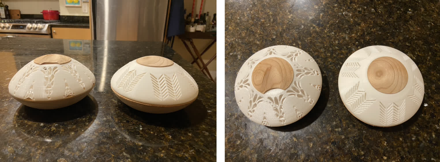
Final selected form. Detailed view:
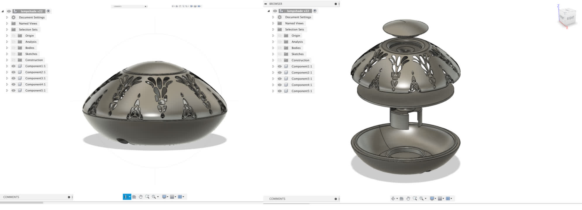
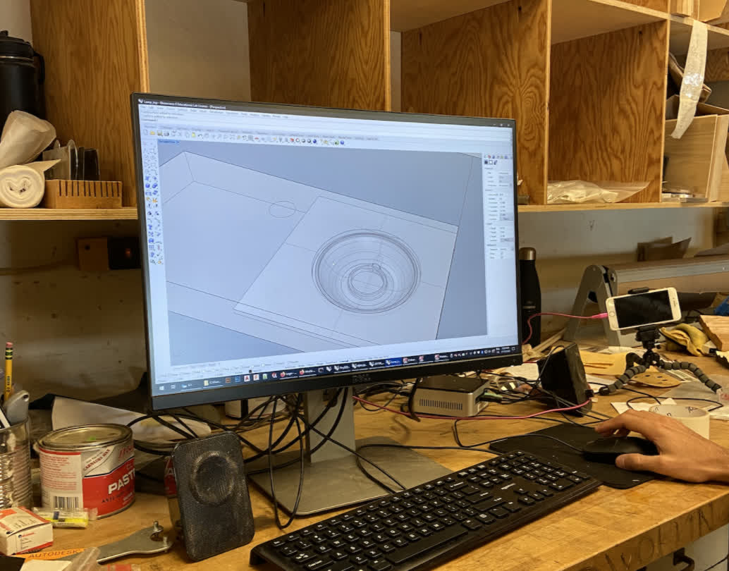
CAM and Milling:
Wooden components exported from Fusion to Rhino to set up for CAM. CAM setup done in MasterCAM.
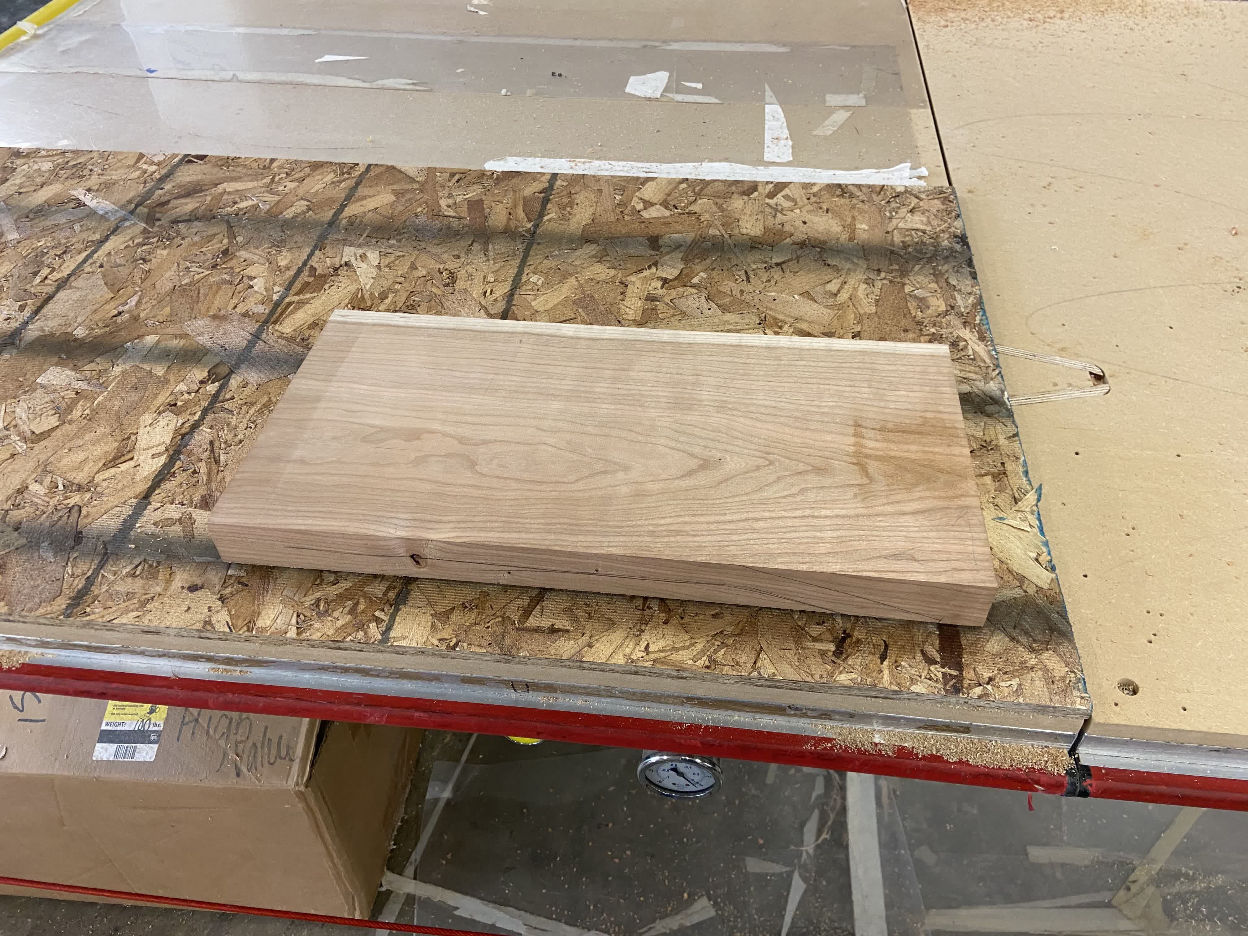
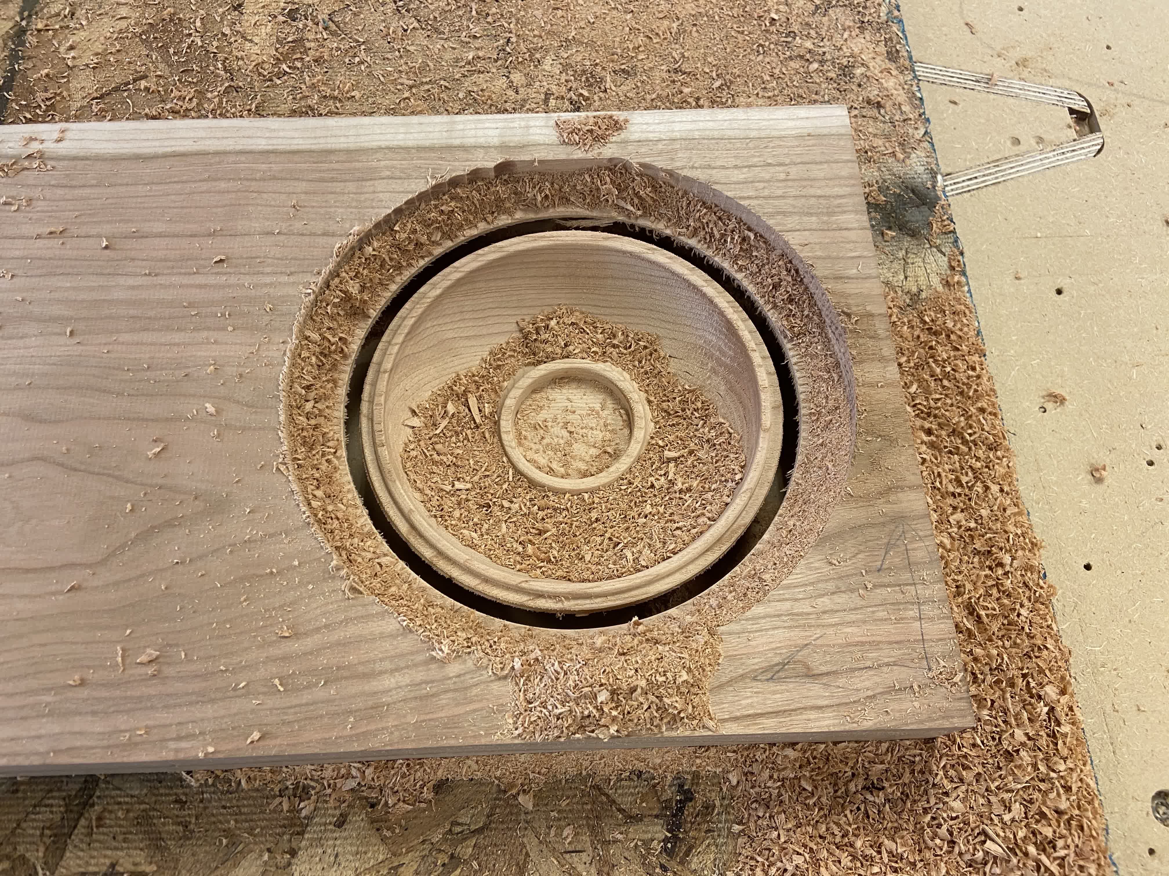
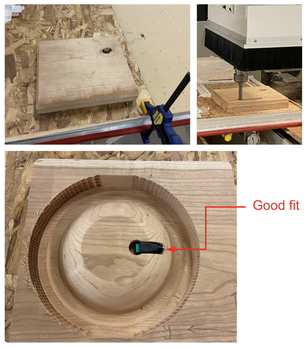
The cherry stock prior to CNC milling. Roughly 8/4" chunk of solid cherry. Flat sawn, so the grain direction/expansion contraction will likely create warping in the final piece, which will ultimately affect the joint between the plastic "shade" and the bottom and top pieces. There are ways to combat this movement, namely cutting and arranging the wood into a circle/hexagon of 20 degree wedges, but in the interest of time, I chose to ignore that rule, and the final product will likely suffer for it. Still, I hope it will be good enough for proof of concept.
Flip milling is the colloquial term for what we were doing. If I had used a lathe to create the bowl shape, making sure the interior and exterior were concentric would be no problem. In this case of CNC milling, we need to make sure the flipped piece is aligned perfectly according to our CAD file. We used a plywood template to ensure placement, and this first run came out pretty well.
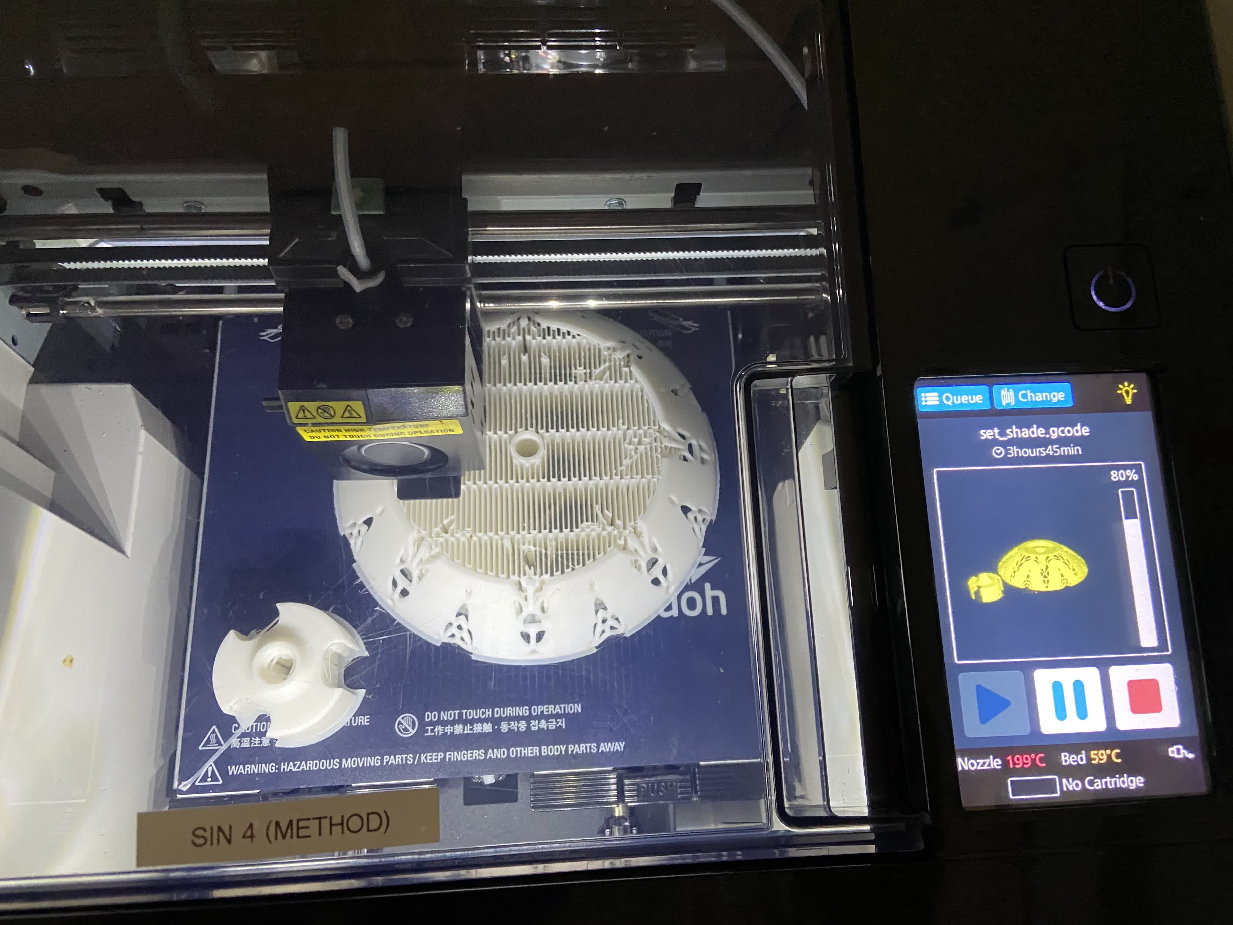
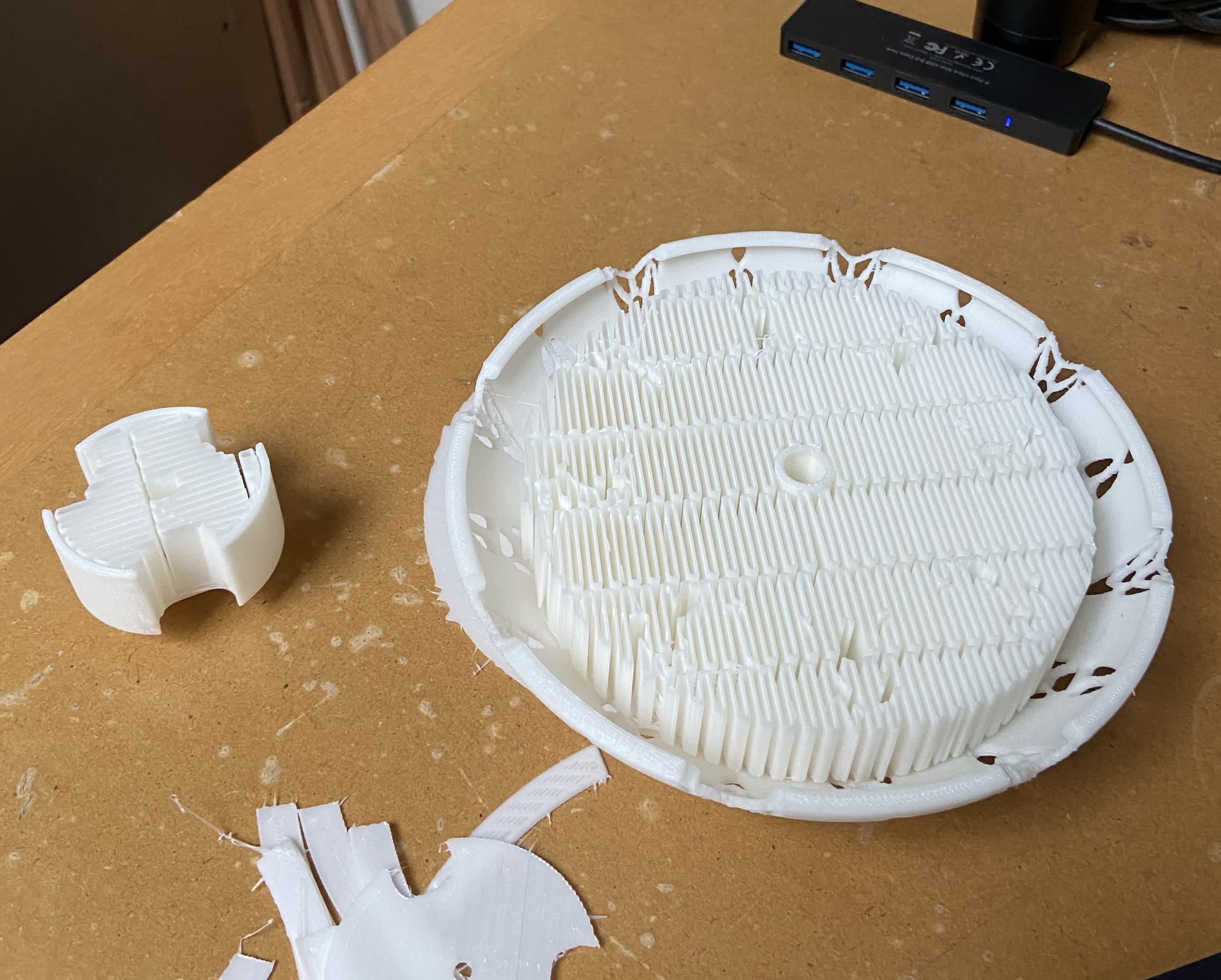
3D Printing:
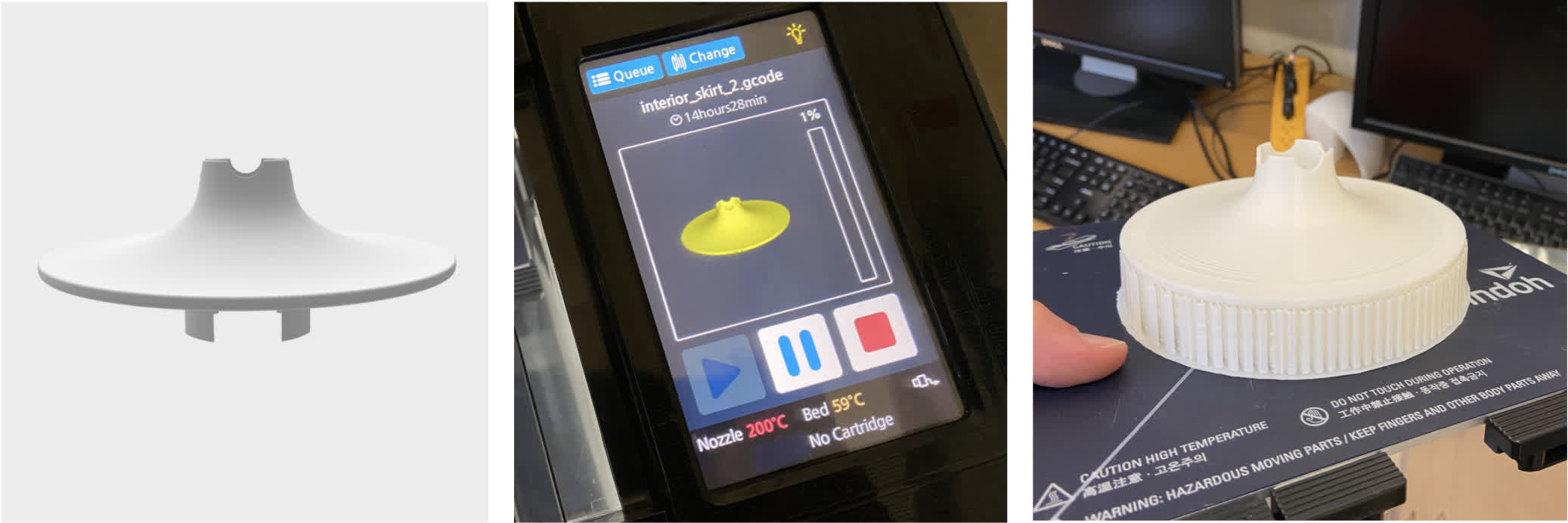
I took advantage of some of the benefits of 3D printing—namely complexity and interior components, but I do think that this first take could still have been achieved via milling or casting. It just would have taken way longer. Even with my print taking 18 hours, that time is passive. I can do other things as the printer works on that piece.
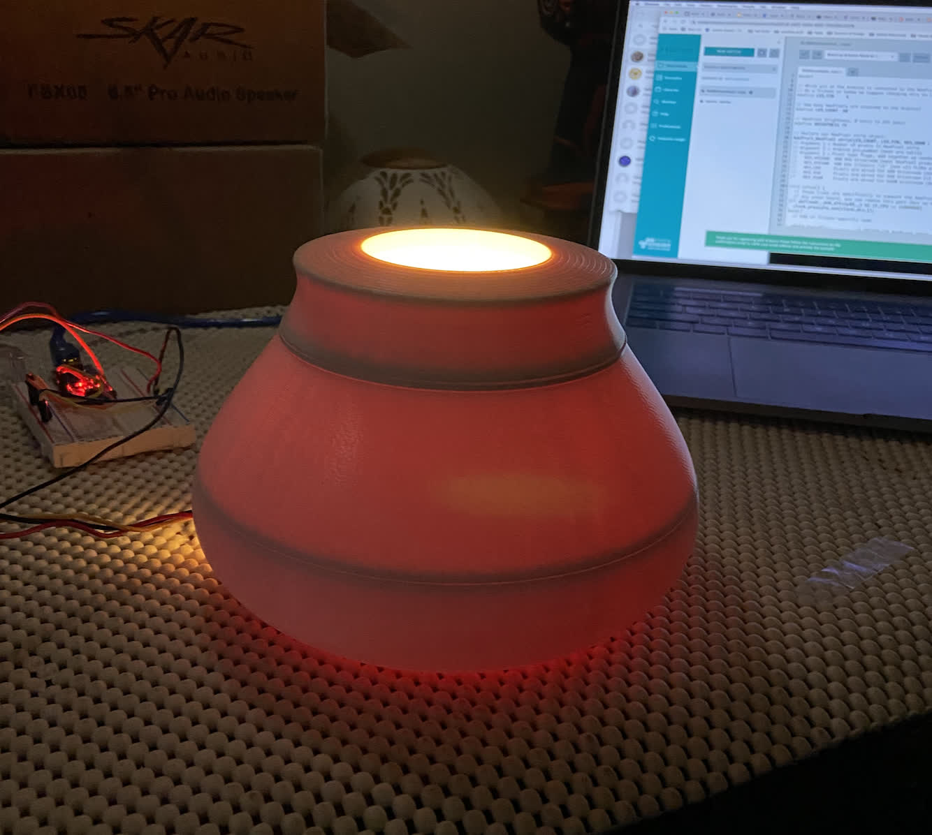
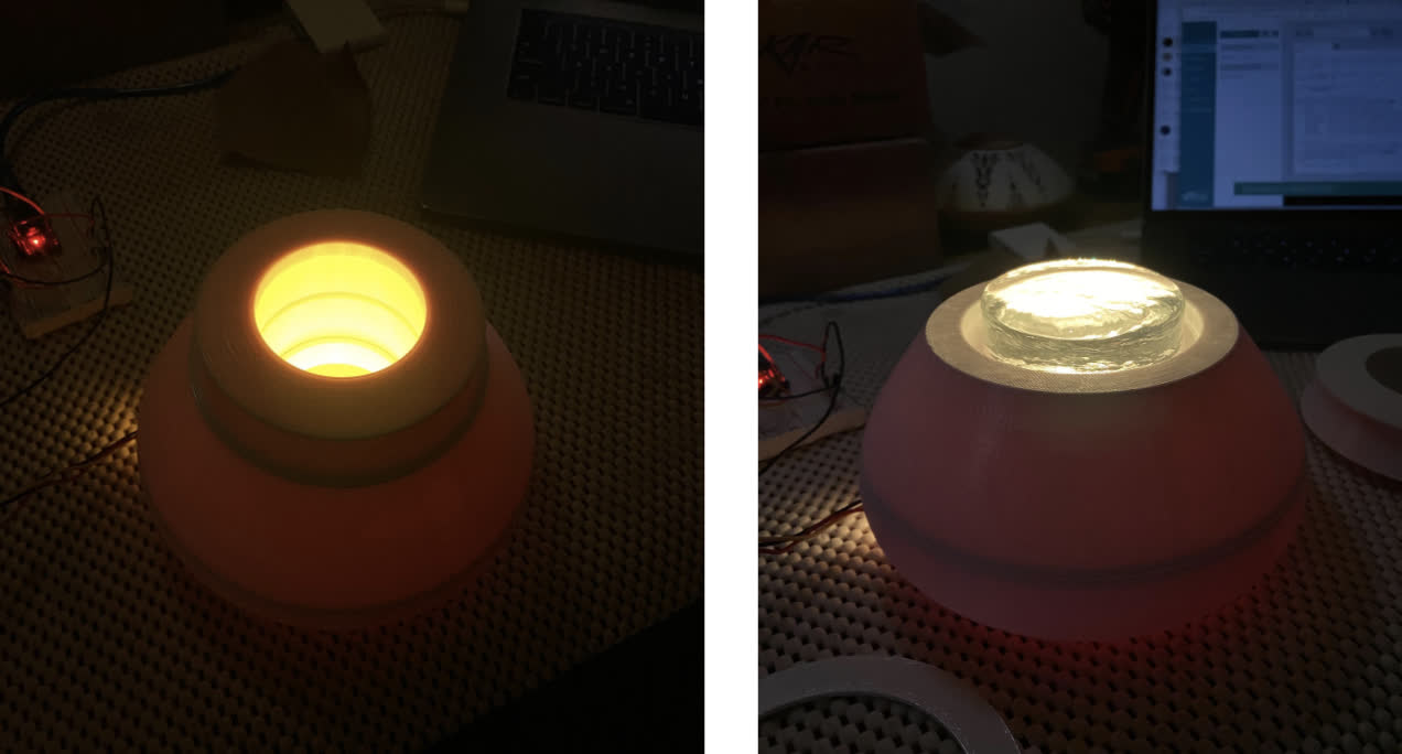
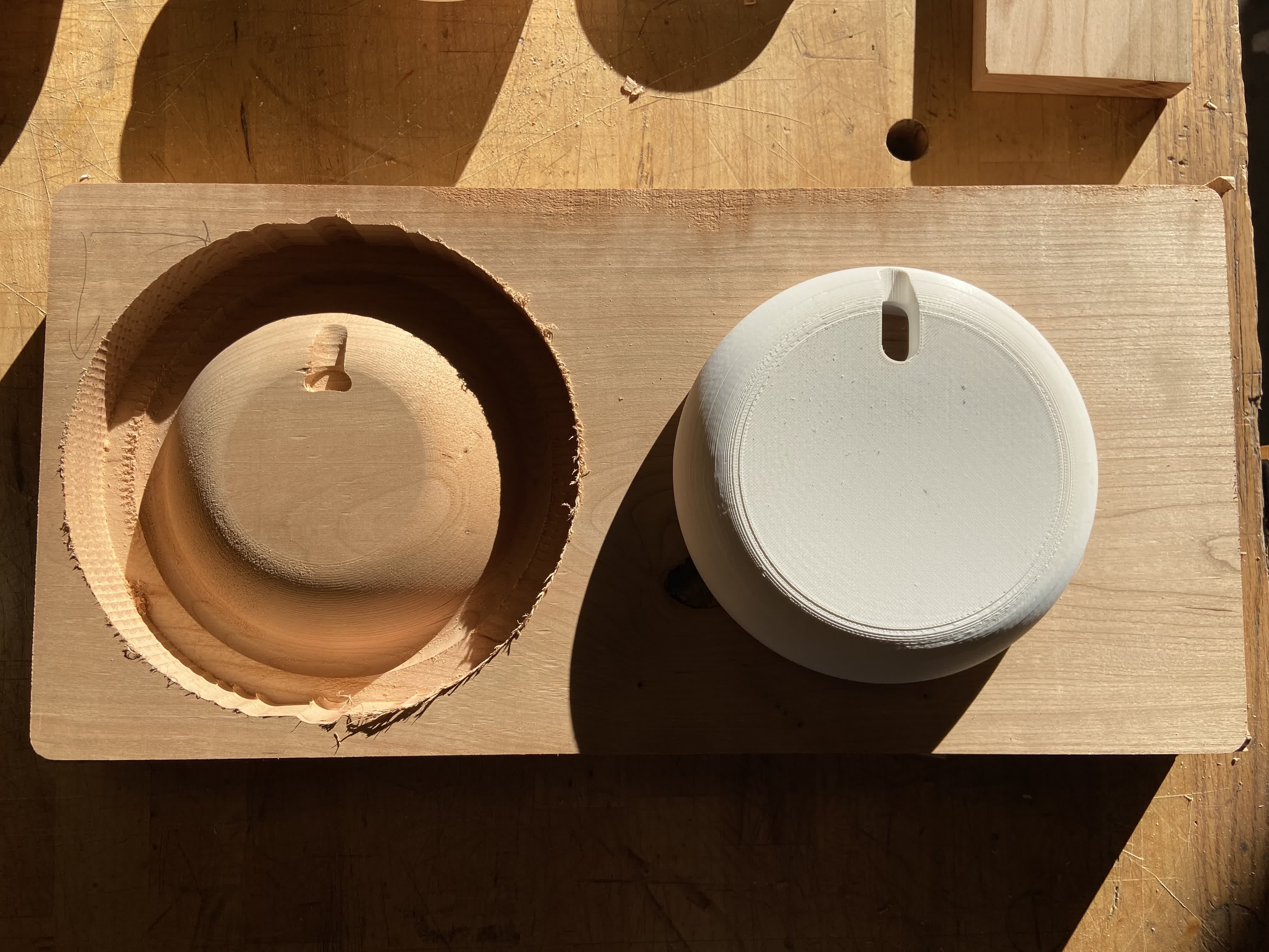
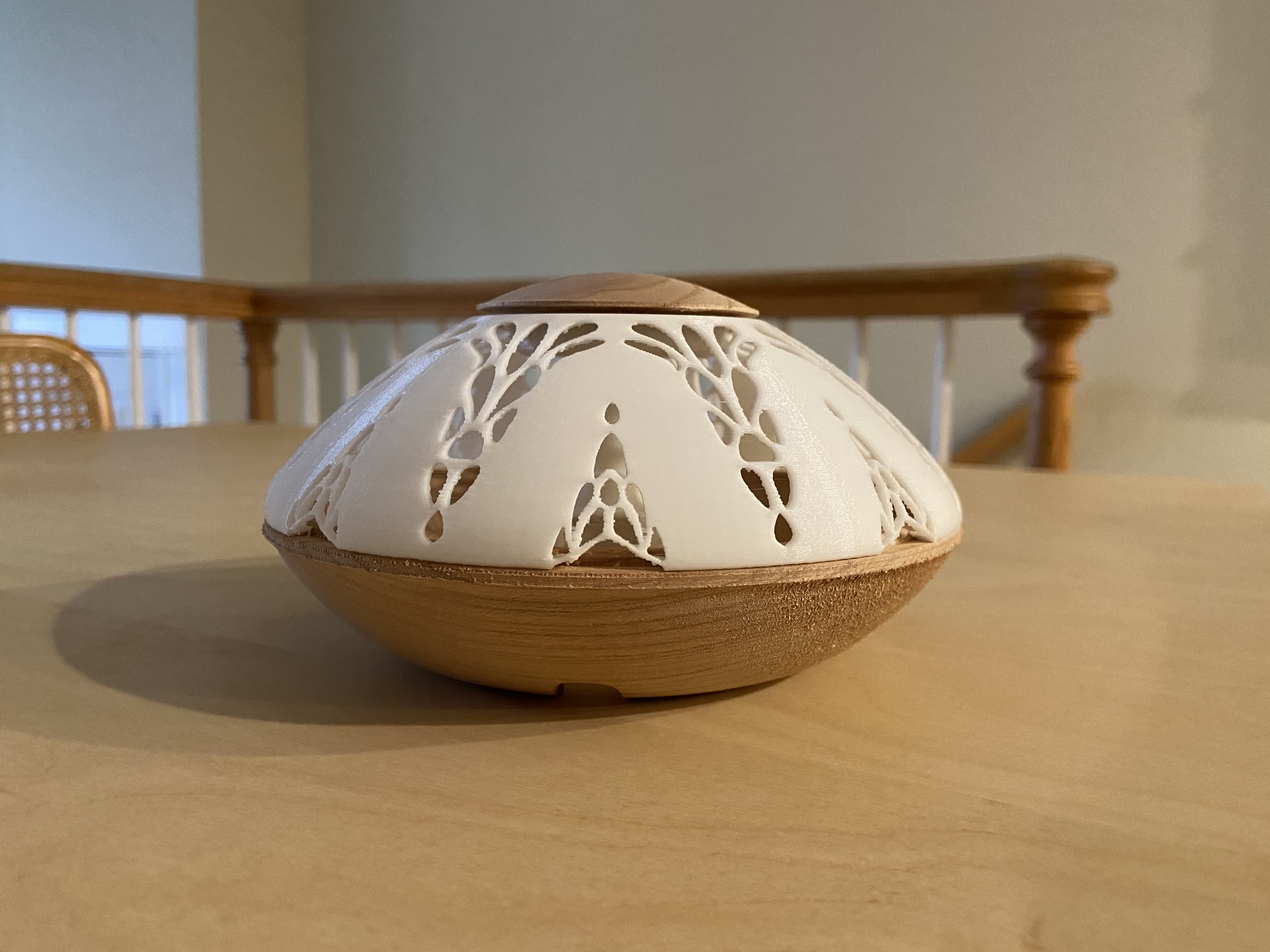
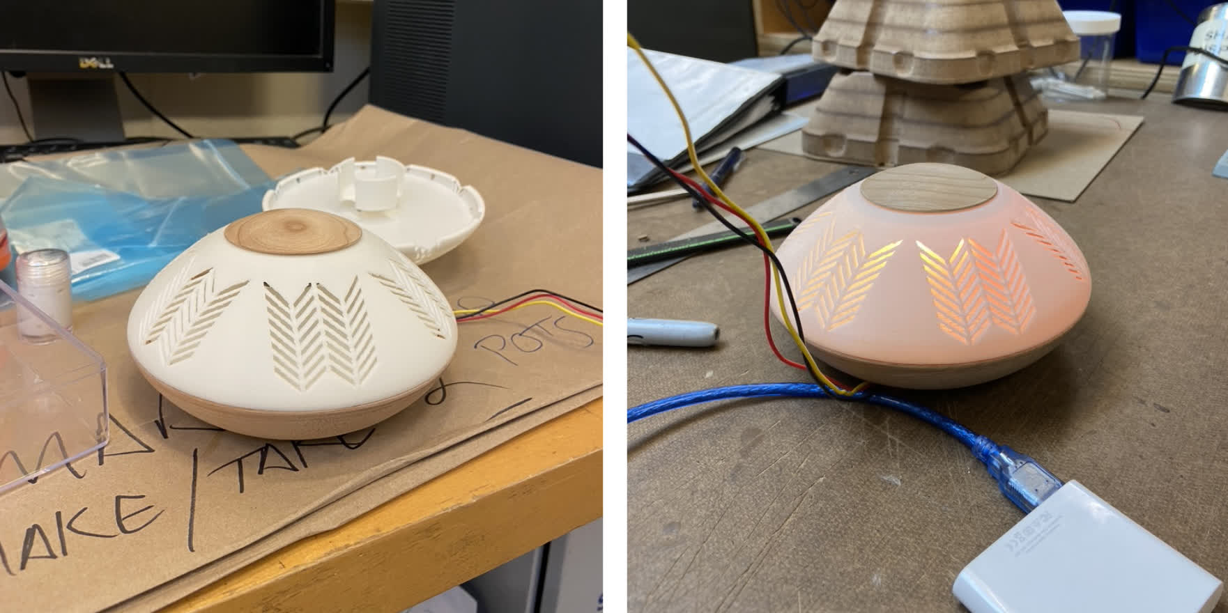
Test Fit and Light Effect:
Nov 17: Version 3
Redesign and Printing:
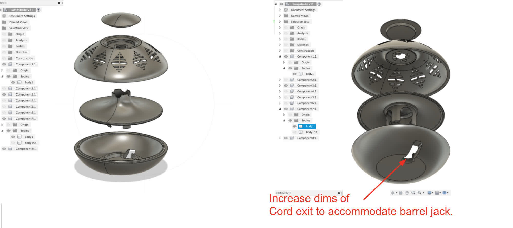
The last version went pretty well, but there were a couple design features that needed tweaking. I also wanted to try out some different patterns on the shade. You can see the changes to the interior component shapes and the placement of the LED below:
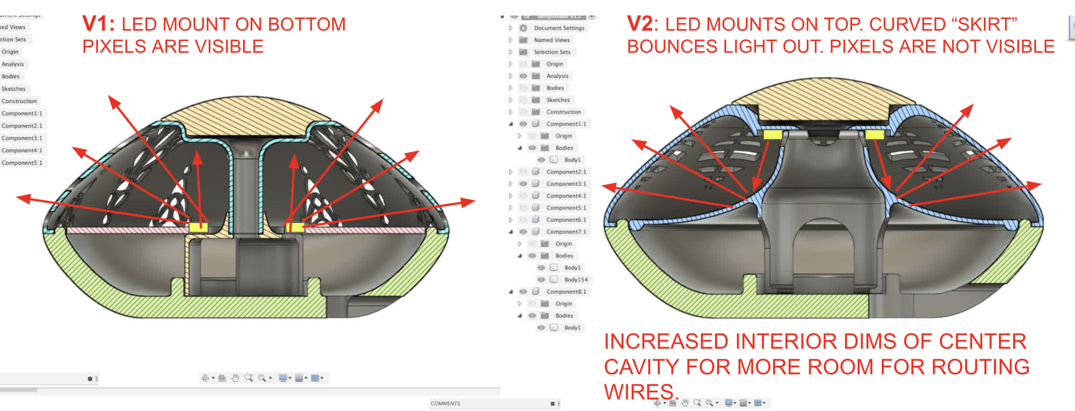
Enlarged cord exit. Called out in red.
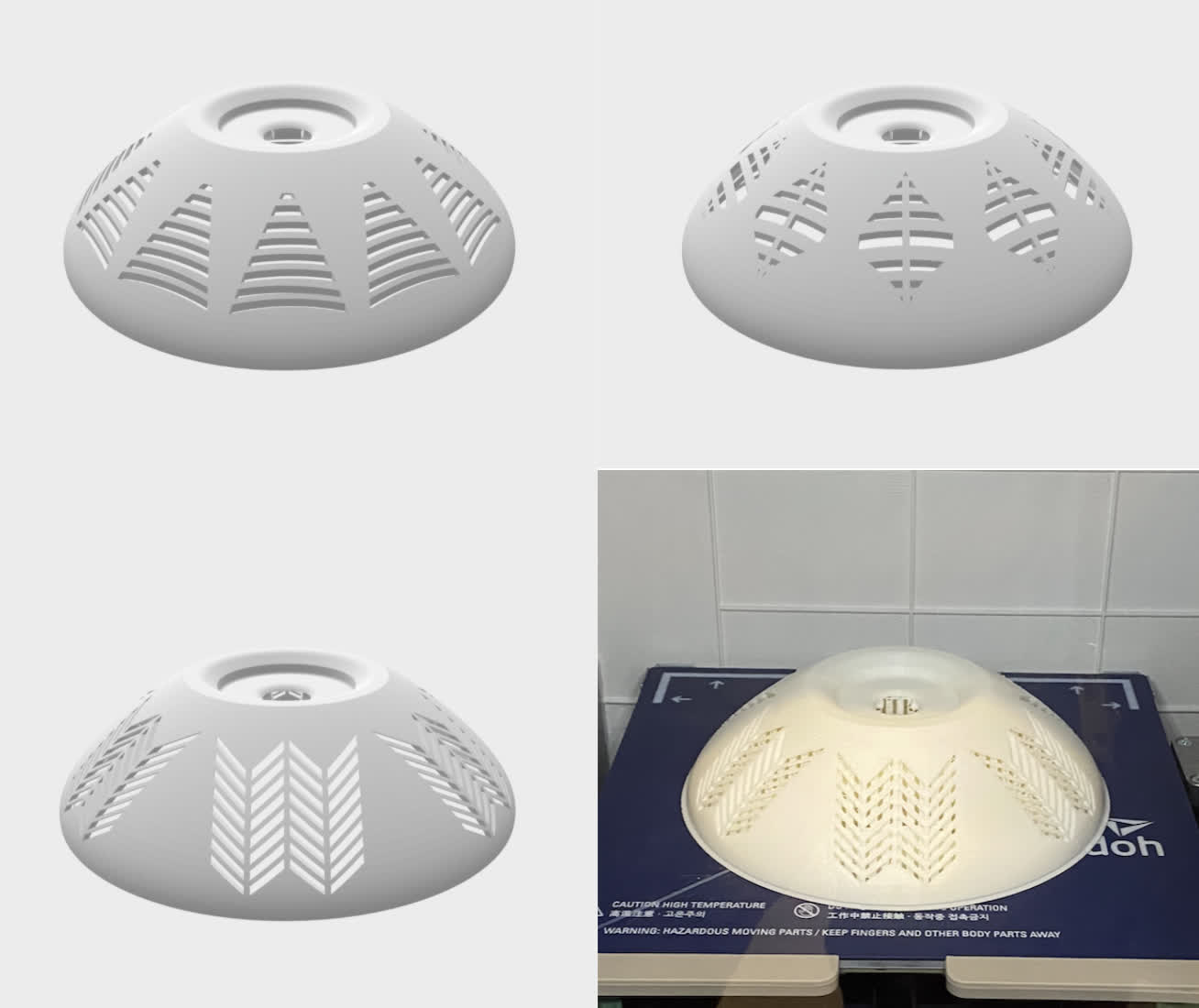
And the new options for the shade. As you can see, I settled on the third option for this version, but I might print the others if I have time.
New skirt design printed.
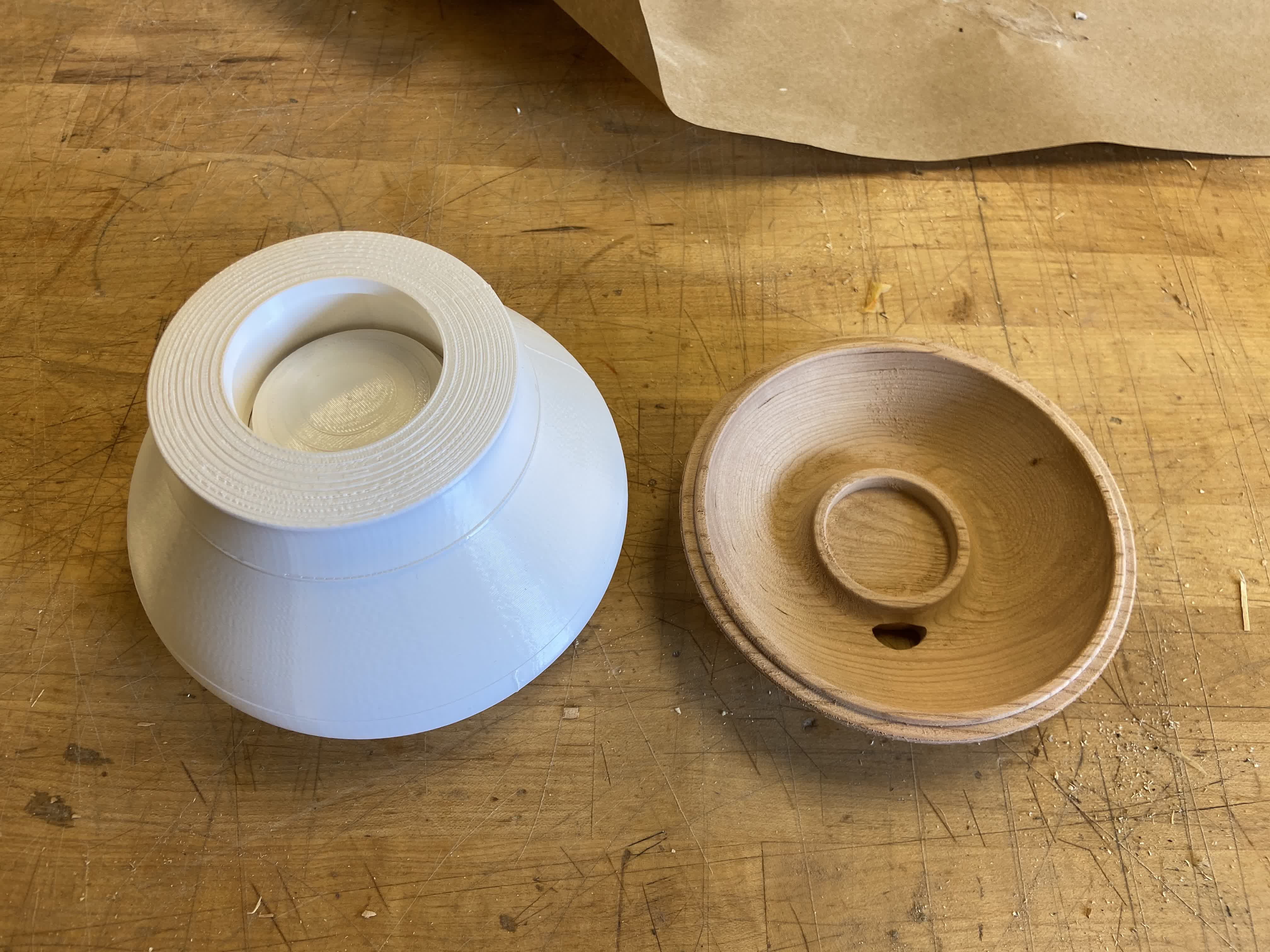
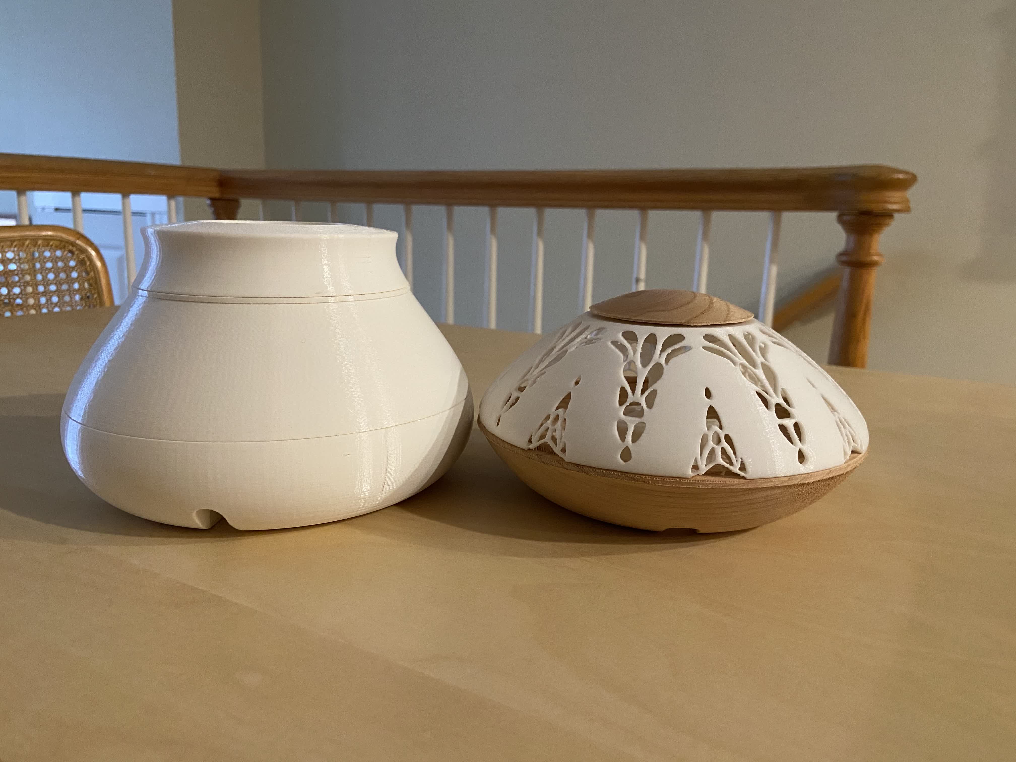
Test fitting the prints with my existing wood components from V2 Proto. They fit well, and the LED sits on the top, thought it's a little loose. I may have to add an encasement or just tape the top to create a tighter fit.
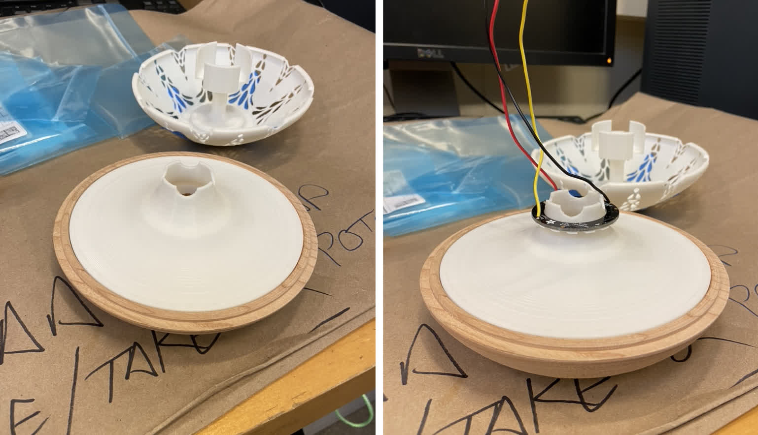
Shade and top fit together nicely. And the LED mounted at the top was a good choice. I can't see it, but the light still emits from the shade well.
Milling again:
Unfortunately, I didn't save the CAM files from last week, which set us back a bit on setup. We also had more trouble registering the pieces on the flip this time. Maybe it was because we were rushing a bit. The top piece came out a little unclean and a little off center. Removing the fillet under the lip did help create a tighter fit, though. So that's something. And the cord exit is now the right dimensions to recieve my barrel jack component.
For the most part, the milled bottom came out nicely, but we missed one pretty critical operation: the final cleanup pass to create the exterior rabbet that receives the shade.
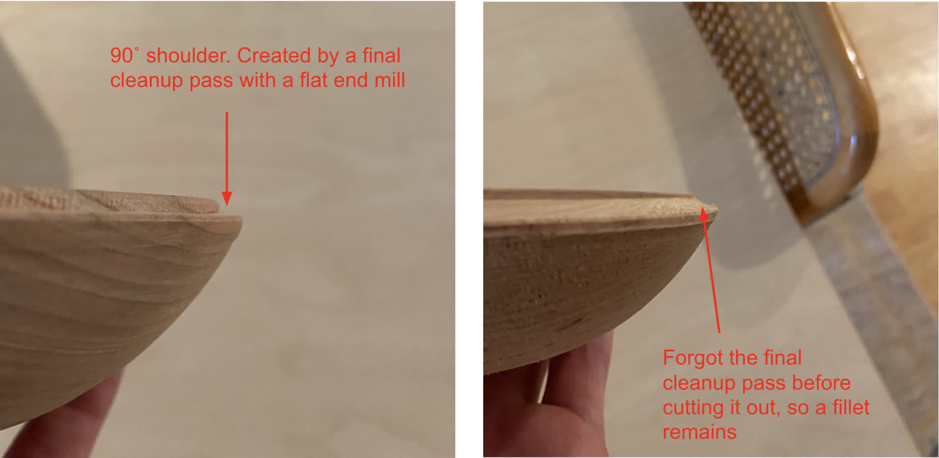
The fit isn't awful, though, so I don't think a complete redo is necessary. Each prototype will simply have quirks, and we'll be sure to improve the design and fabrication process down the line.
What's next? Electronics
I have created a board with a phototransistor input and another board that uses the NeoPixel as an output, but I need to integrate the two.
I also need to start planning out the capacitive sensor--its shape, functionality and placement. This will be my task for the next week.
If I have time and can figure it out, I'd like to get these lamps interacting with each other. I have two, why not use them both. Again, depending on time, I may try to have them communicate via bluetooth. If that is too daunting, I will simply wire them together. That will likely be a task for next week.
Nov 24: Figuring out the device behavior
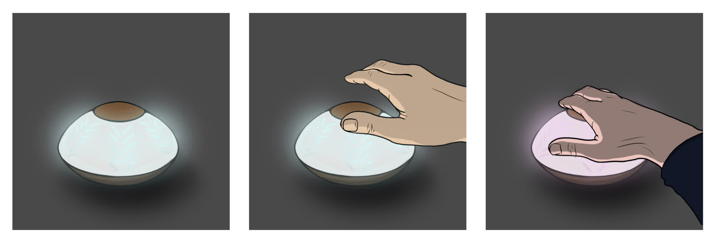
Vision for reactive color changing:
NeoPixel and ATtiny woes:
I really like the NeoPixel for its versility. I've used it before with an Arduino Nano, and I found it really easy to program to perform a variety of functions. But when I tried to integrate it with the new ATtiny series chips, I immediately ran into problems.
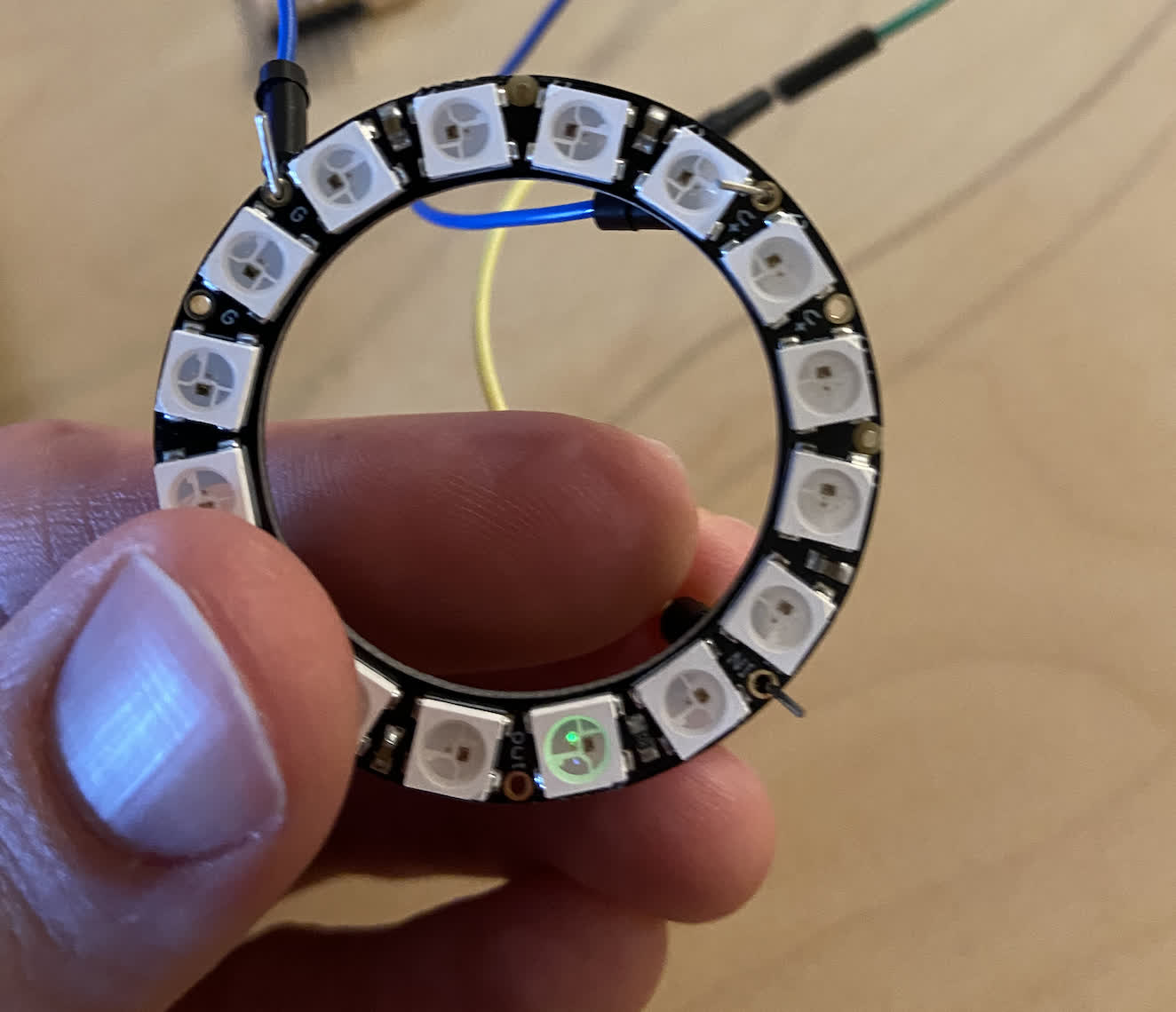
This is a standard example sketch "Strand Test" for the NeoPixel, running through Arduino Nano. It is running perfectly, so the NeoPixel itself is working.
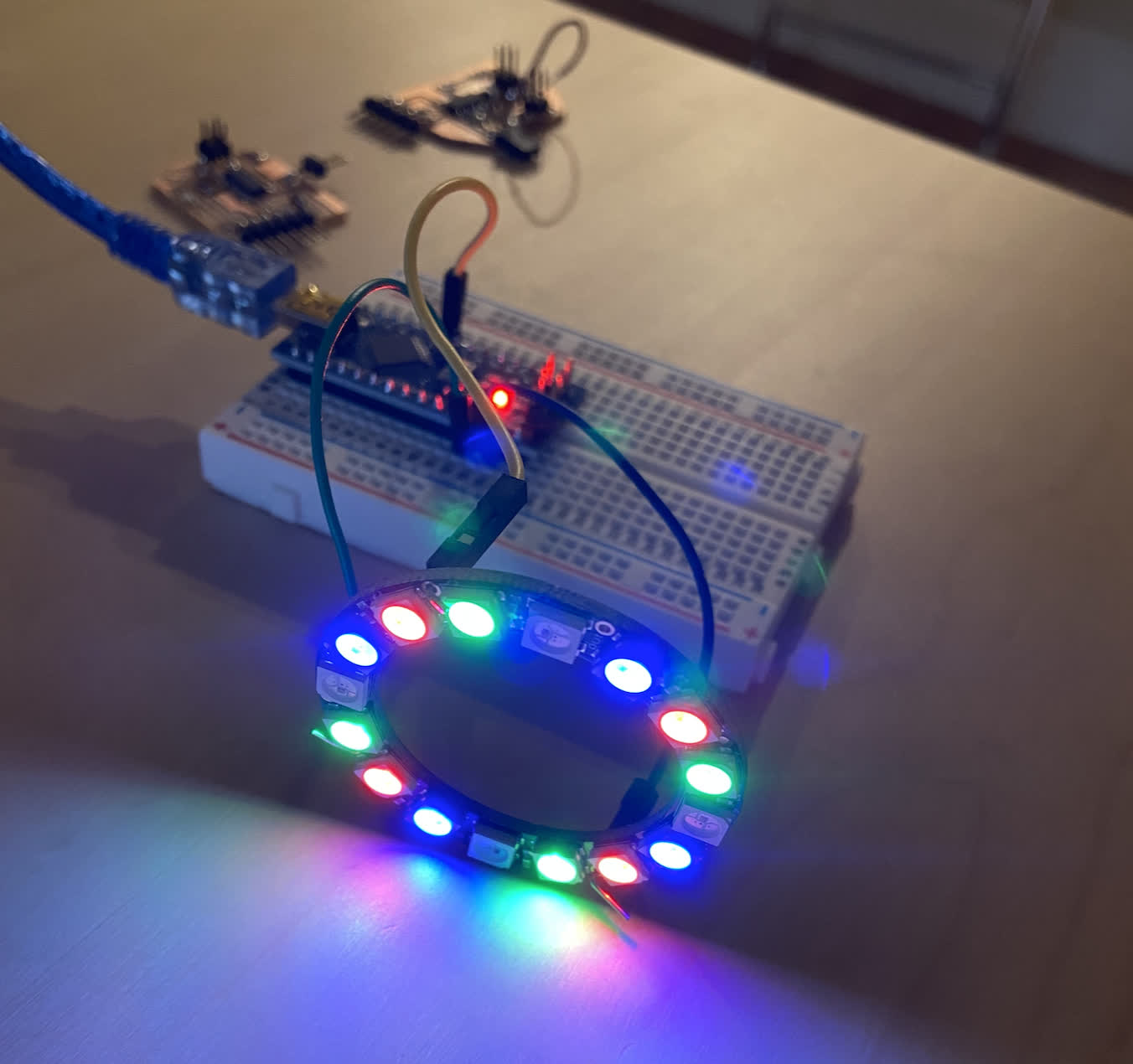
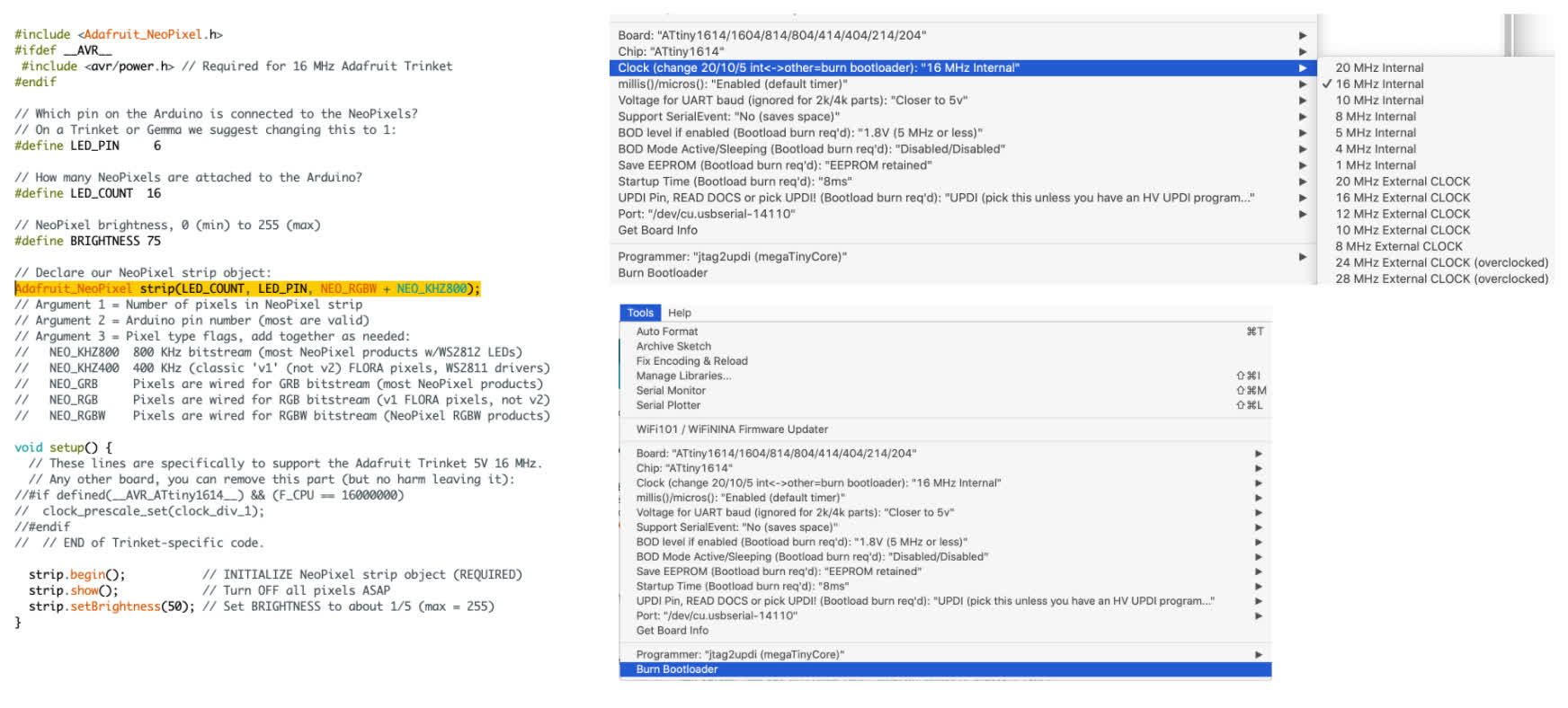
According to the NeoPixel Uberguide, the LED strips or ring need a single pin connection to the board (in addition to ground and power). In this case, I chose digital pin 6 per their example. And I created a 1614 board with the requisite pin hooked up. See the chart for Arduino pin 6 on the board:
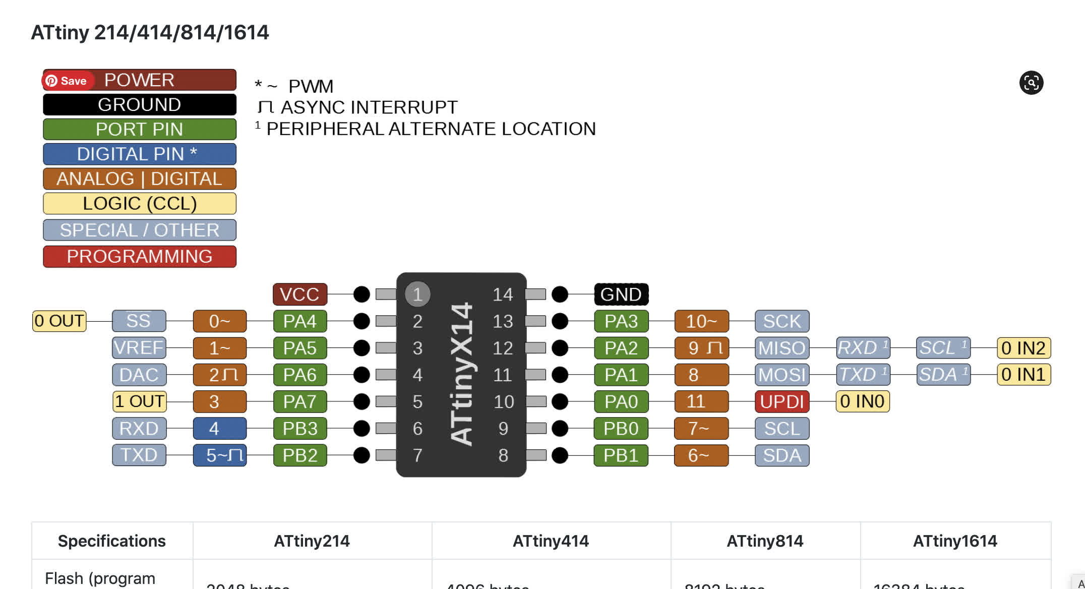
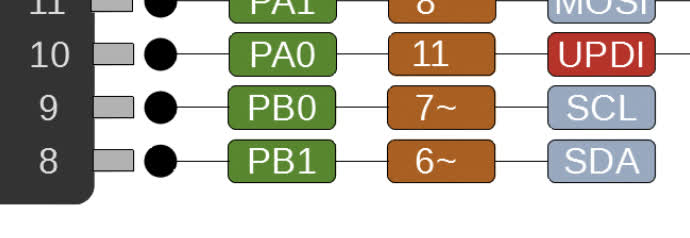
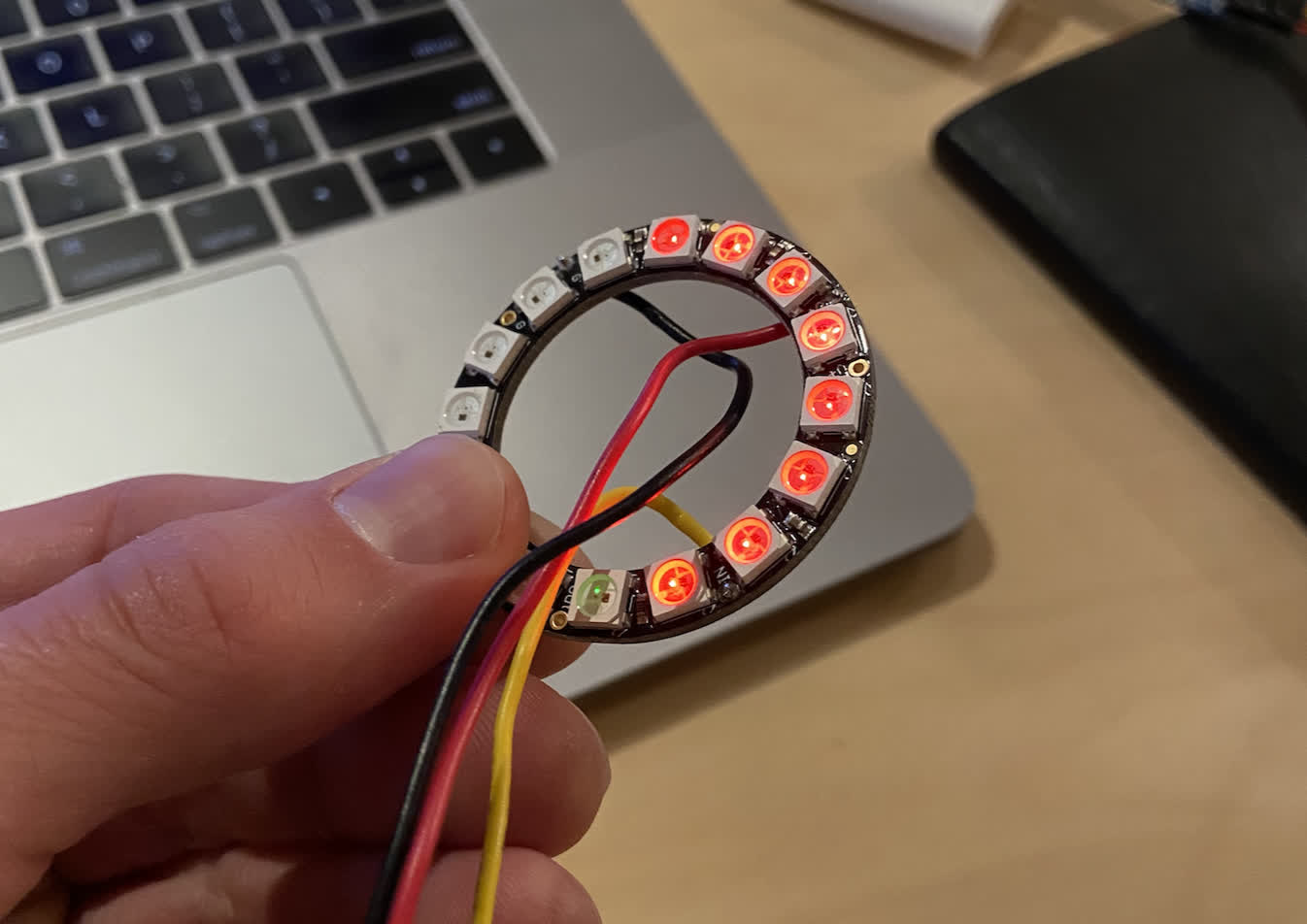
You can see week10 for a full account of how this went on the first try. After some board troubleshooting, the connection should work, and the NeoPixel should run correctly, but it didn't. Instead of the full strand test color cycle, I got a few lights to light up and only shining red. This was programmed using the FT232 and UPDI.
This was frustrating. The working theory we came up with was that there was an issue with the ClockSpeed between the ATtiny series and the NeoPixel. I raised an issue asking about this, and I got a variety of responses, which were helpful in considering the reality of pushing farther down this road. I think a viable alternative is to create my own LED ring. And I may still do this, but I also wanted to work with Anthony to see if we could make this work a little better.
I did some pretty intensive digging online to see if anyone had successfully used these components together, and I found a couple.
1. This instructables IKEA Star light. was a good resource to show that these products can work together. It also mentioned that the clock speed needs to be changed to 16MHz instead of 20MHz.
2. This Newton's Cradle project actually successfully used ATtiny1614, which was a good thing to see. It also provided a guide to converting the Arduino Nano into a UPDI programmer.
I showed these to Anthony, and he came up with a few plans to try out. The first was to change some aspects of the code I was running in the Strand Test.
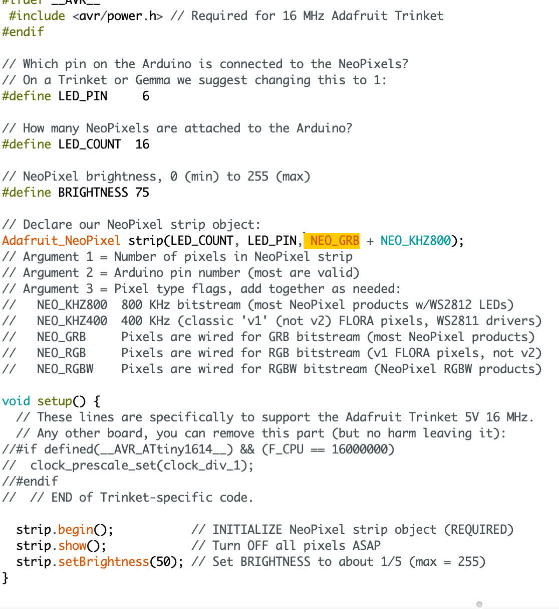
I toggled the the Adadfruit_NeoPixel strip(LED_Count, LED_PIN, NEO_GRB + NEO_KHZ800) line a few times. Changing NEO_GRB to NEO_RGBW for exmple. But in using ftdi, this didn't change much. In some cases it resulted in no light at all.
So the next thing we wanted to try was to convert the Arduino Nano into a UPDI programmer because it should be to "natively" run ATtiny series. Anthony found an even better resource for doing this:
A Step-by-step guide to turn a uno/nano/pro mini into a UPDI programmer
We did this succesfully, and I not able to upload Arduino sketches directly instead of using the hex file method through pyupdi. That said, I ran the sketch to see if the NeoPixel would respond differently, and we got a frustrating non-result.
I tried toggling the same aspects of the code, this time changing NEO_KHZ800 to NEO_KHZ400, and I got a more responsive output. Still not what we're looking for, but I got a red color wipe.
Anthony kindly offered to help me troubleshoot this by purchasing a NeoPixel product of his own. He bought a strip of LEDs and had no problem running a Strand Test on the lights. We think it may have something to do with the compatibility of the 400KHz version that I think I'm working with in the Ring. The strips run on 800KHz, and they appear to run more easily, so I bought some. They should arrive next Tuesday, but I may begin designing my own custom light board as a contingency plan. I can't push this much further. I have other problems that need my attention--namely in the networking department.
The new product arrived on Tuesday, but I wanted to doublecheck my old board with the ring because I hadn't in a while. I had been programming the 1614 boards all day, and had no problem, so I hooked up the board and the LED to my converted Nano programmer, checked the tool settings were at 16MHz, burned the Bootloader, and uploaded the Strand Test code with NEO_RGBW + NEO_KHZ800 selected. It came out working exactly as it should.
I had another one of those moments were I was floored that this thing I'd been working on for days had suddenly started working seemingly out of nowhere. Thinking it might be a fluke of the board, I tried it with my other 1614 board, and it worked with that too. I'm not sure if I changed something inadvertently and didn't track it, but now I have the setup down, and I know that I can make the NeoPixel ring and the ATitny1614 work together, so I'll take it.
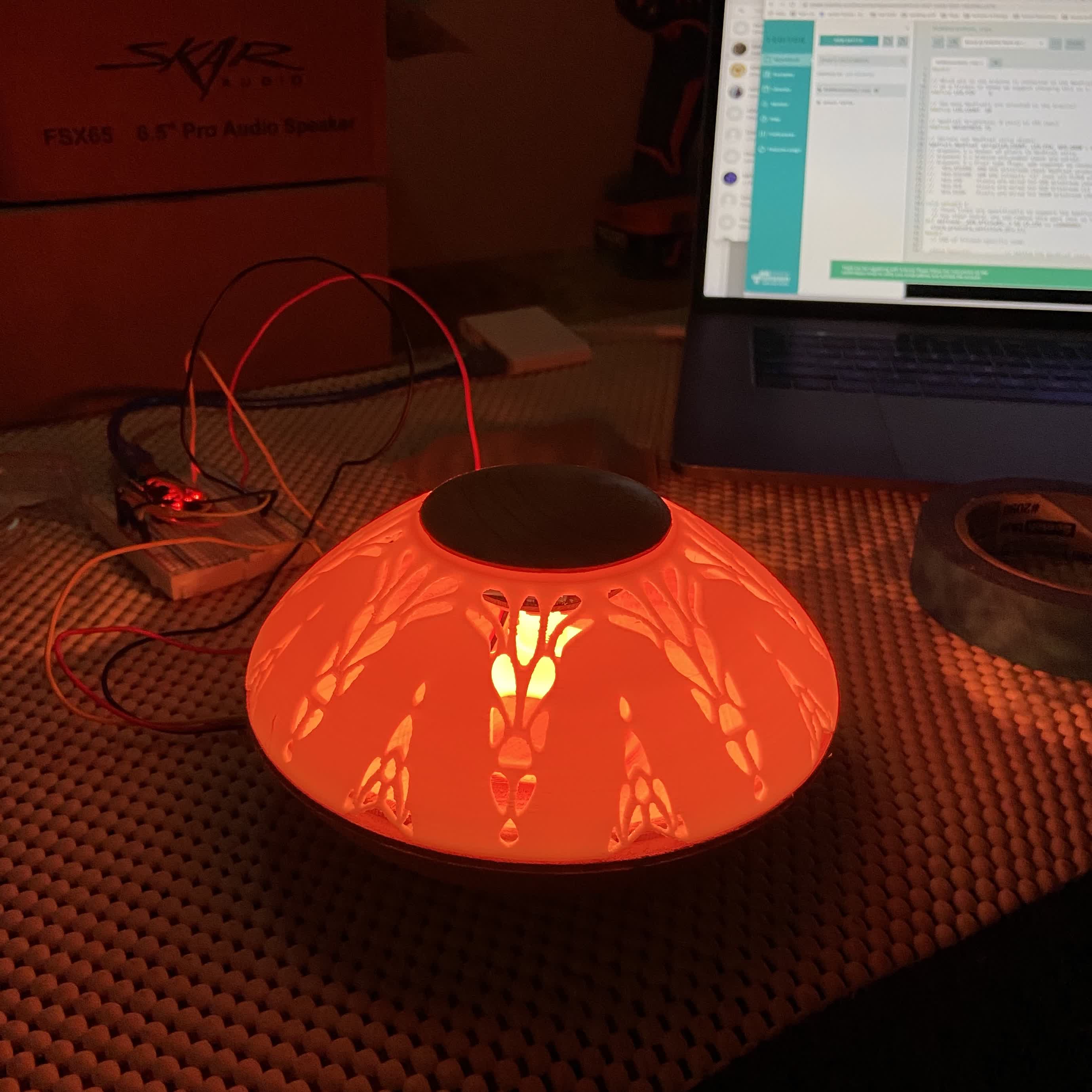
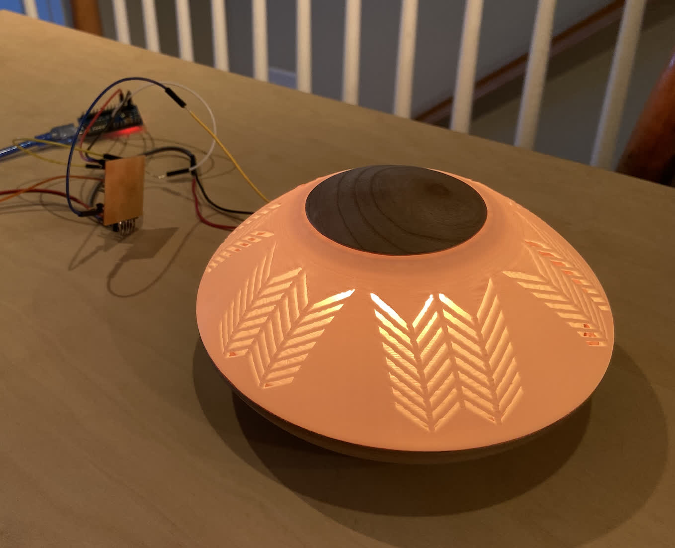
I did some toggling of the NeoPixel code to make sure it was definitely responsive. I also wanted to check it out in the housing. Here's some purple shining from inside the packaging for good measure:
The wiring right now is really ugly. I could shove it all inside the packaging, but I think I'll refine the setup before I do. See the mess of wires:
I was curious as to whether I could get a ATtiny412 board to work with the Pixels as well, so I change the settings in tools and uploaded the code, but I got nothing. I decided to move on for now because I have something working, but I'll circle back to that issue when/if I need to use a 412 board.
Hooking up a Phototransistor:
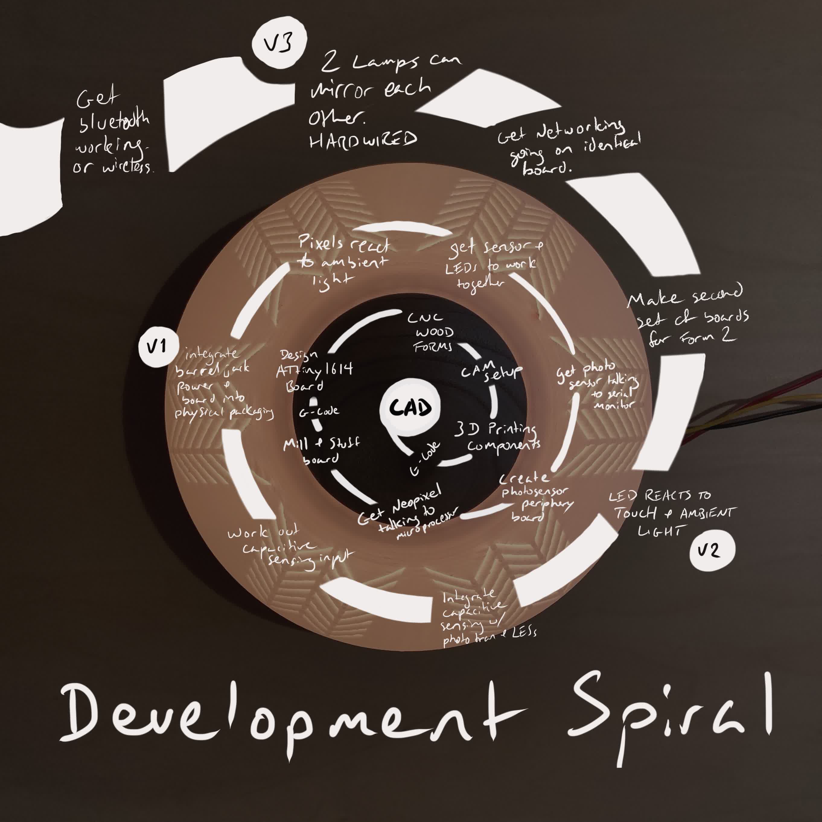
I had grand ambitions for this project that didn't seem so grand at the beginning. At this point, major triage is in order, so I sketched out my Spiral Development plan to visualize the benchmarks of potential versions of this project. I will likely only get to Version 1 by next week, and I'll need to decide if I want to integrate capacitive sensing or if I want to move forward with integrating my application interface. I don't think I'll have time for both.
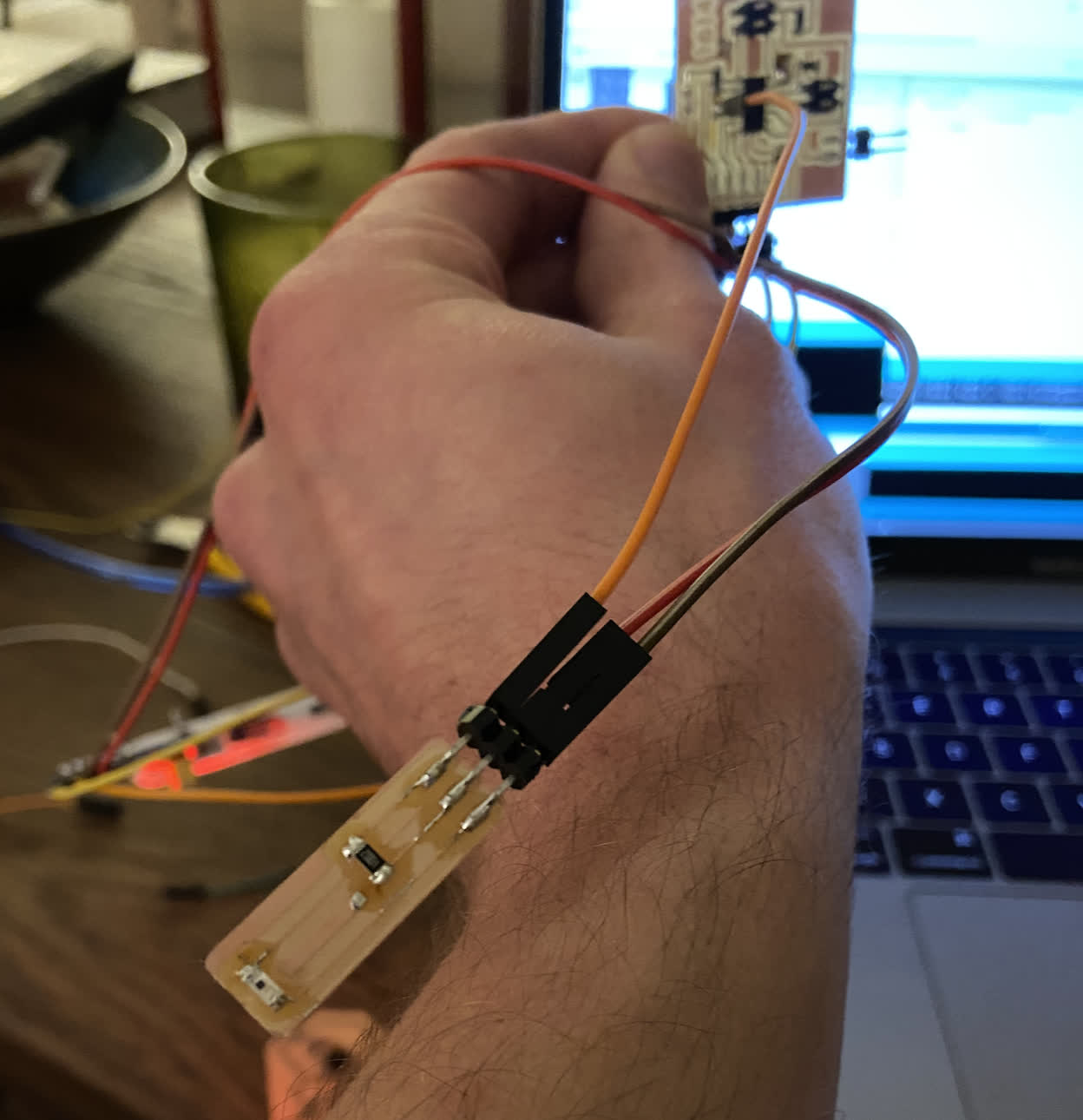
With this in mind, I really wanted to get the phototransistor up and running. I have been having a hard time getting two different sizes of the ATtiny series to speak to each other via serial--I have had success getting 412s to speak to 412s and 1614s to 1614s, but I haven't succeeded in getting them to speak to the others. I only have one working ATtiny1614 board right now, so in the interest of time--and in the interest of rapid testing--I created a breakout board for my Phototransitor to connect directly to the board that is already talking to the NeoPixels.
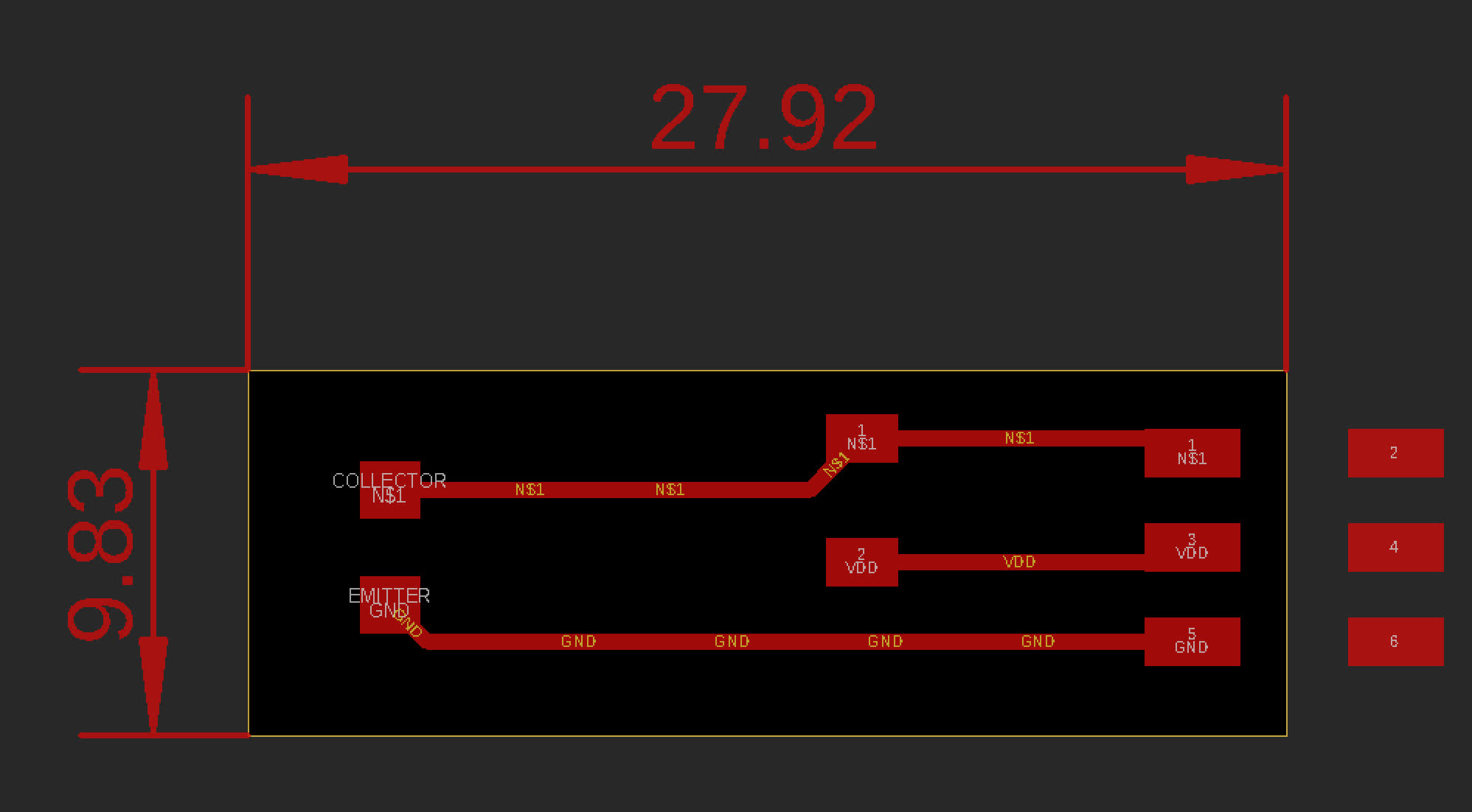
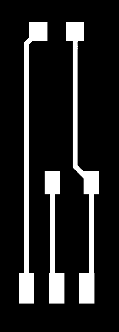
I used an engraving bit to mill the board, and it had a blunted tip, which I think may have been the reason that the traces came out so thin. They were usable, especially considering how simple the soldering was, but it's still something to look out for if I'm going to make another board. I'm running out of board material.
Here's the board all stuffed and hooked up to the main board:
And here's a serial monitor test to make sure it's taking a reading and writing a value.
Files:
photo_breakout.sch
photo_breakout.brd
photo_breakout.ai
photo_breakout_traces.png
photo_breakout_interior.png
Attempting to Integrate the Phototransistor and the NeoPixels:
My goal here is simple: I want the NeoPixels to turn on when its dark out and turn off when it's light out. This should be fairly straight forward, but if other experiences with this project have anything to say about it, we know that's a bad assumption to make.
So. Where are we. I know I have this board working with my LEDs, and I know I have this board working with my phototransistor. Conceivably, this should just be a matter of telling the LEDs to listen for a value coming into the analog pin from the sensor. I think that is the general concept, but I am falling short in how to write out the statements.
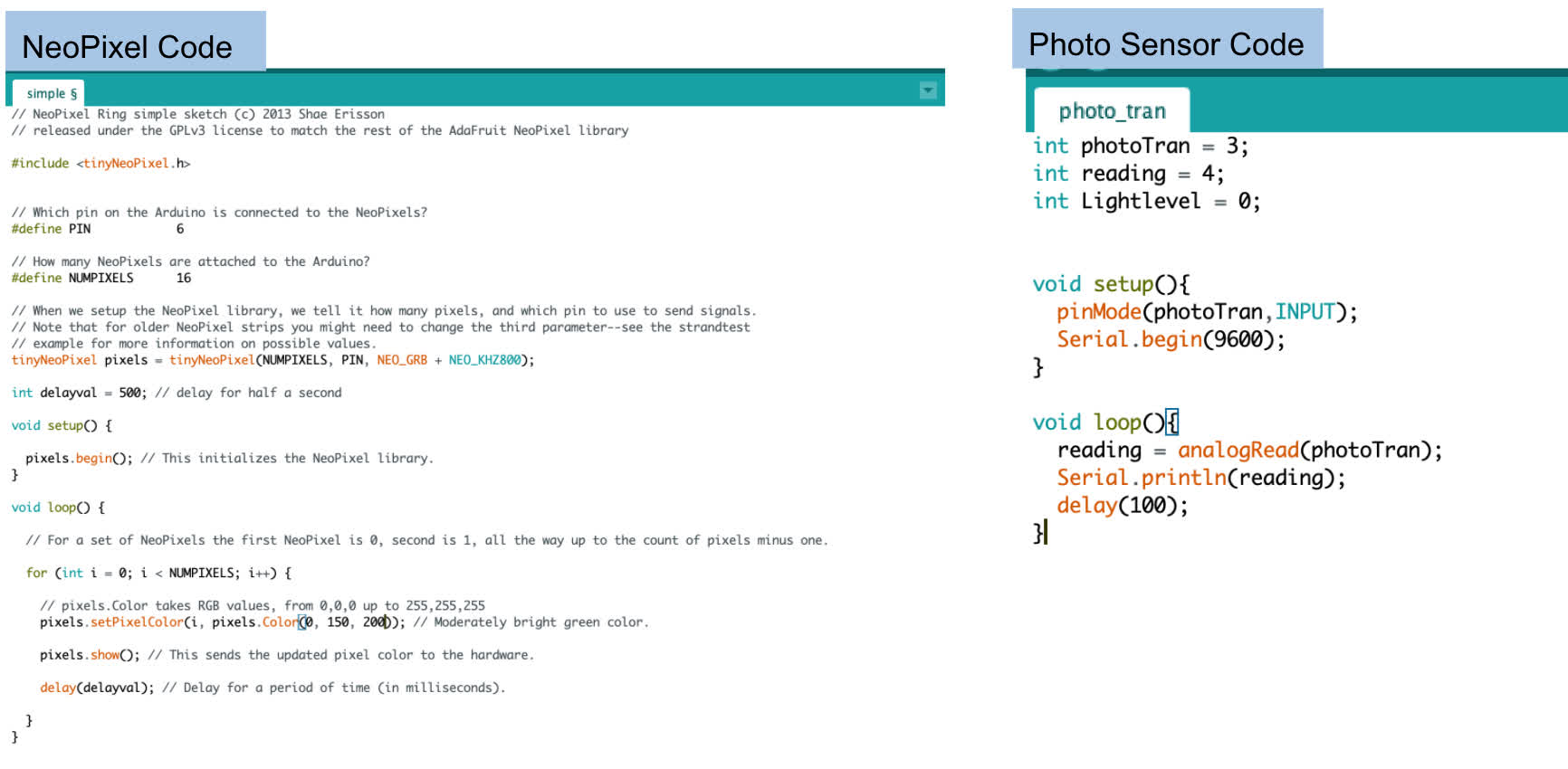
Here are the examples of code that has worked with each individual component:
Probably a foolish approach, but I just tried dumping my photo transistor example into the void setup and void loop of my NeoPixel example:
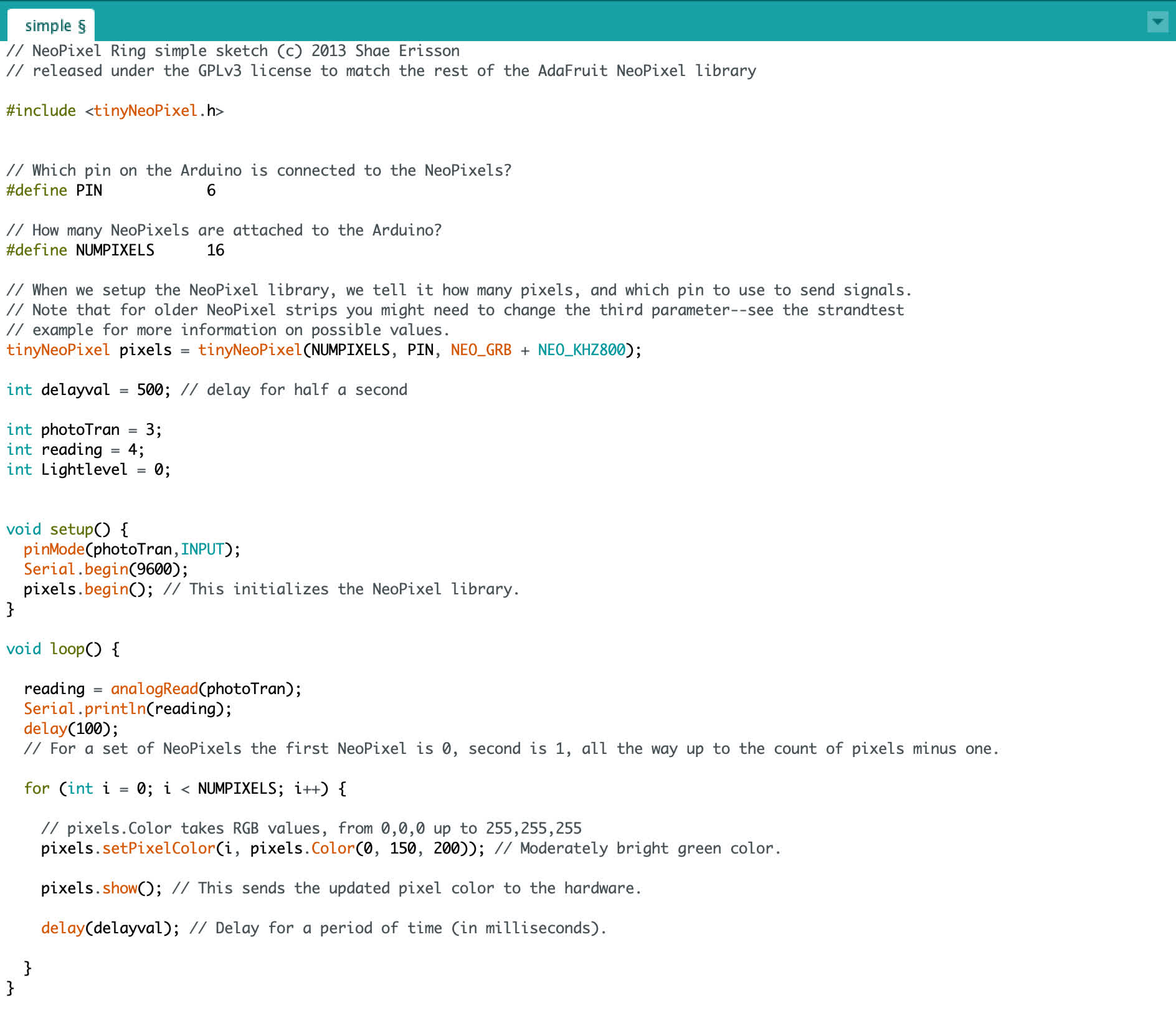
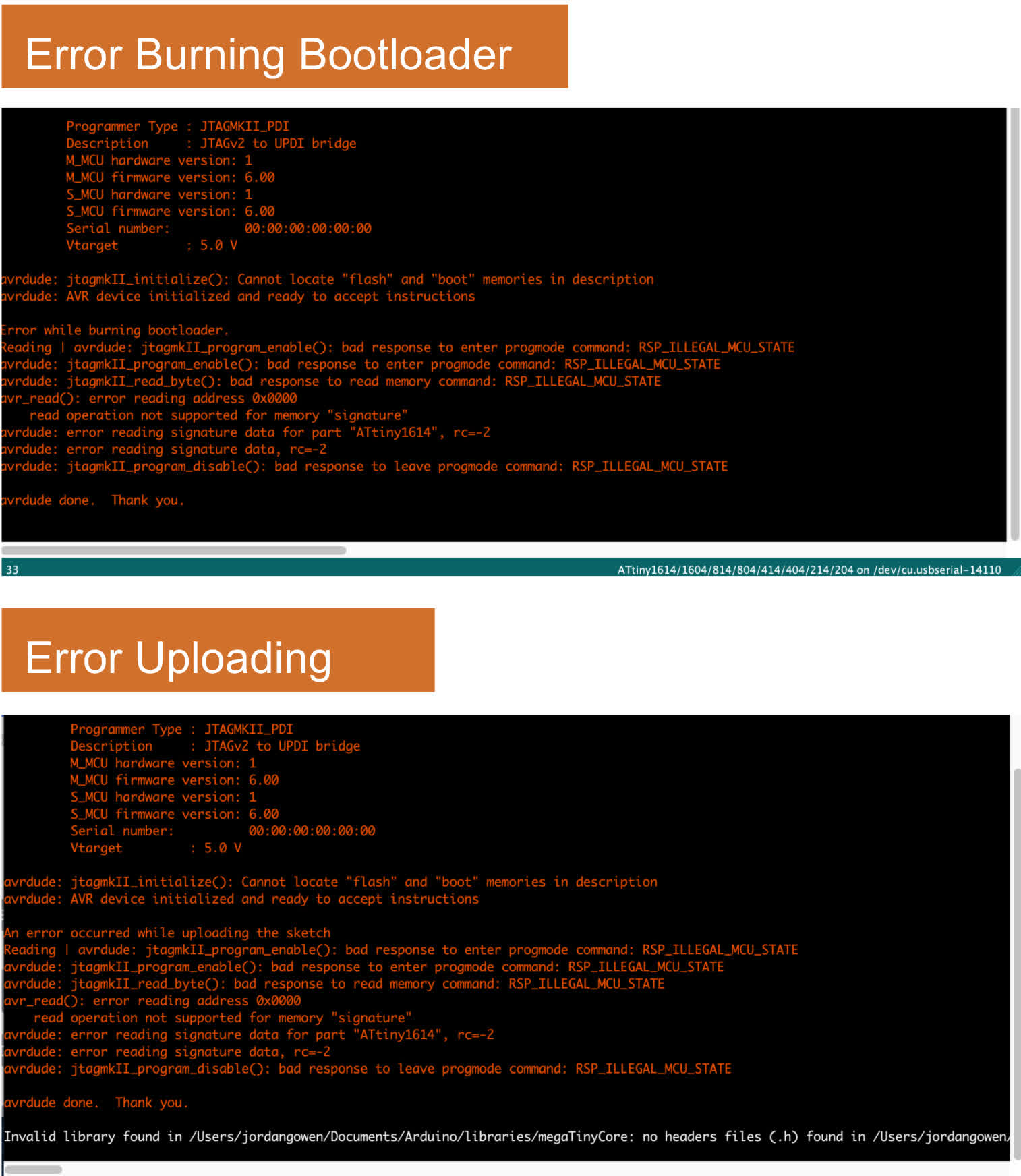
I didn't work. I got errors burning the bootloader and then, obviously, got an error when I just tried to upload for the hell of it.
Time to take a step back and look at some examples of similar work. Or reach out for help.
Successfullying Integrating the Phototransistor and the NeoPixels:
I have found that taking a step back and simplifying the task helps to speed things up in teh long run. Not a profound or original notion, but it's a habit I've been breaking through much of this project. With that in mind, I decided to simplify my task and test that my phototransistor can turn an onboard LED on and off.
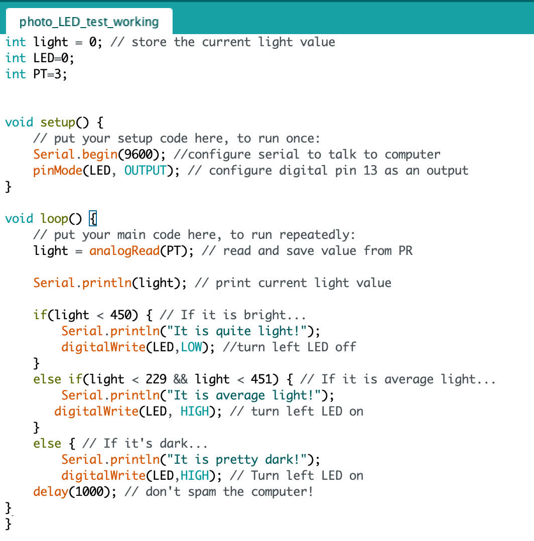
Seeing as I have an LED blinking and a phototransistor communicating sensor values through serial, this was a pretty easy task to accomplish. Here is my code with an if statement telling the LED to turn off if the sensor value is less that 450. There are two else statements, which are irrelevant for the binary choice of turning off or on, but the middle range will provide a different serial readout about the state of the ambient light in the room.
Successful test:
So that went well, and I'm comfortable with creating that interaction. Tell the LED pin to flip LOW or HIGH based on input value. Where I am a little unsure is how to get this same interaction to happen with the NeoPixel. I was hoping it might be similar to the onboard LED--just be a matter of writing High or Low for the single pin connecting the NeoPixel to board. So I took a sht with this code:
Unsurprisingly, this didn't work. I had assumed that the NeoPixels are too smart for a simple toggling of the power to work, and Anthony confirmed this. But we were most of the way to getting this system to work. He suggested a very simple workaround for turning the NeoPixels on and off: Change all the RGB values to 0 if I want the pixels to turn off. This would be the working code to make that happen:
            for (int i = 0; i < NUMPIXELS; i++) { // pixels.Color takes RGB values, from 0,0,0 up to 255,255,255

              pixels.setPixelColor(i, pixels.Color(0, 0, 0)); // probably off
              pixels.show(); // This sends the updated pixel color to the hardware.
              delay(delayval); // Delay for a period of time (in milliseconds).
              }
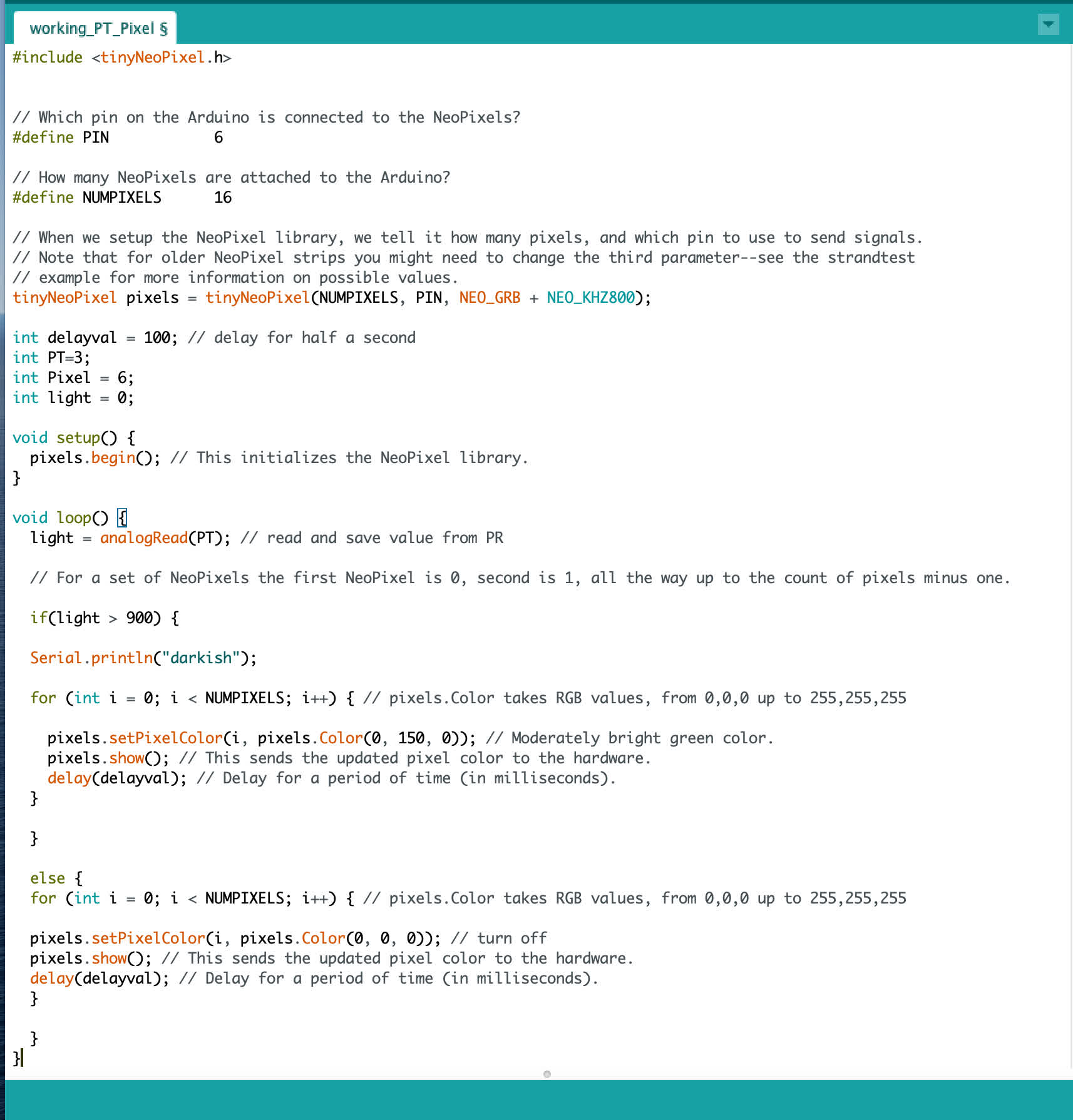
From here, I just needed and if and else statement to tell the NeoPixels to respond to the sensor value. Here is an example of working code:
The moment of truth:
Wow. It finally works! What a simple function, but it's so satisfying to finally have it working. No I can play around with changing colors and check the fit of the board in the housing.
Integration with Packaging
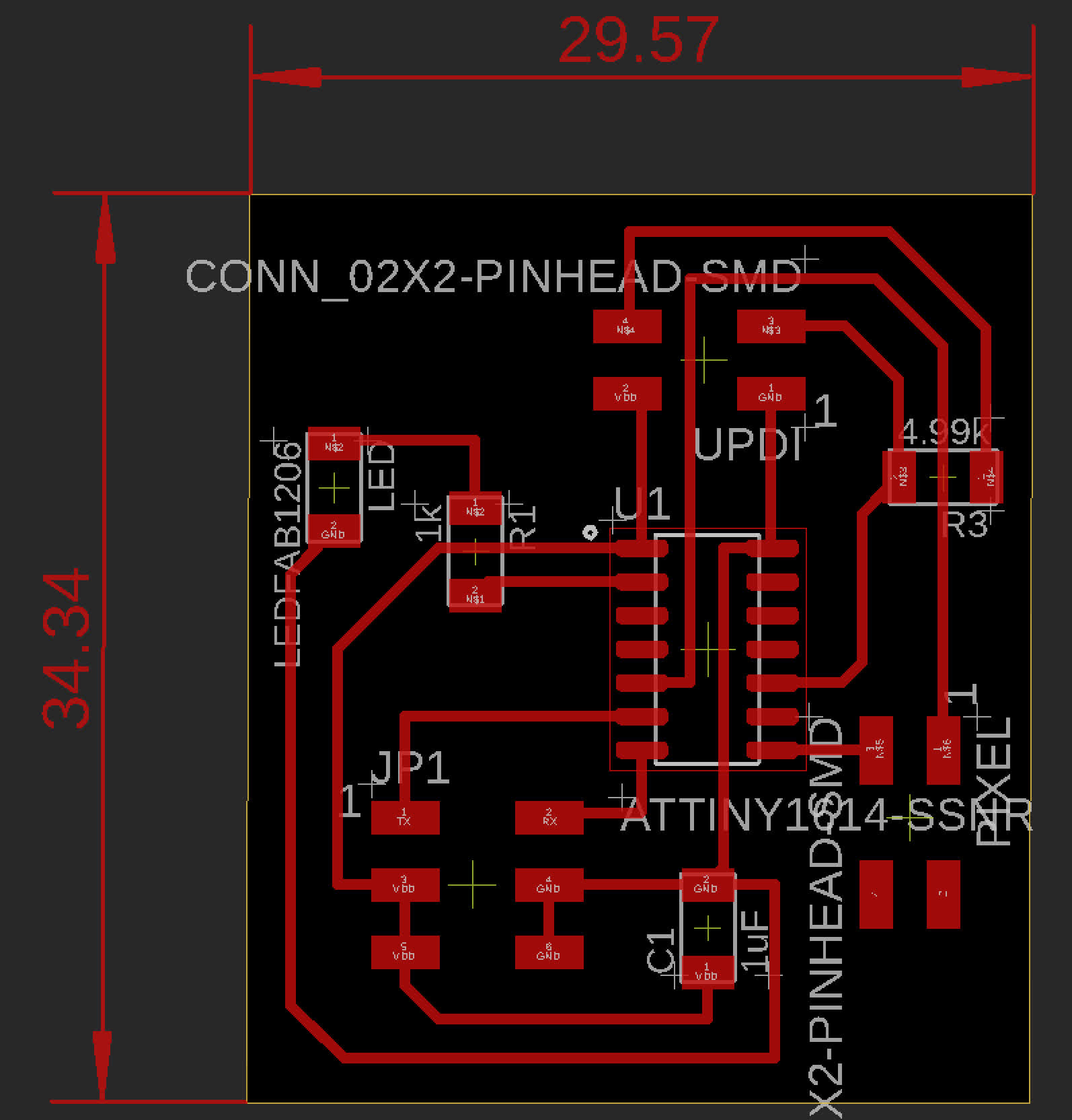
While the existing board fits inside the housing, the pin connectors--the FTDI and the digital pin for the Pixels--exit the board laterally, which makes running the wires a little difficult. So I designed a new board with only vertical pin connectors to decrease the footprint in planview when it is fully wired up.
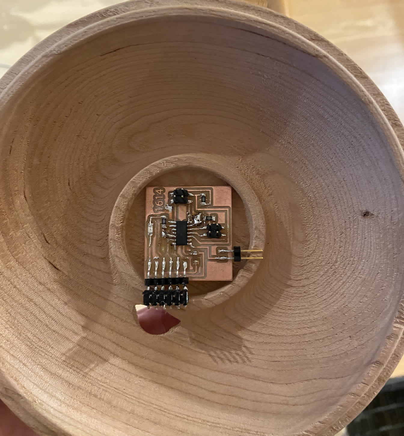
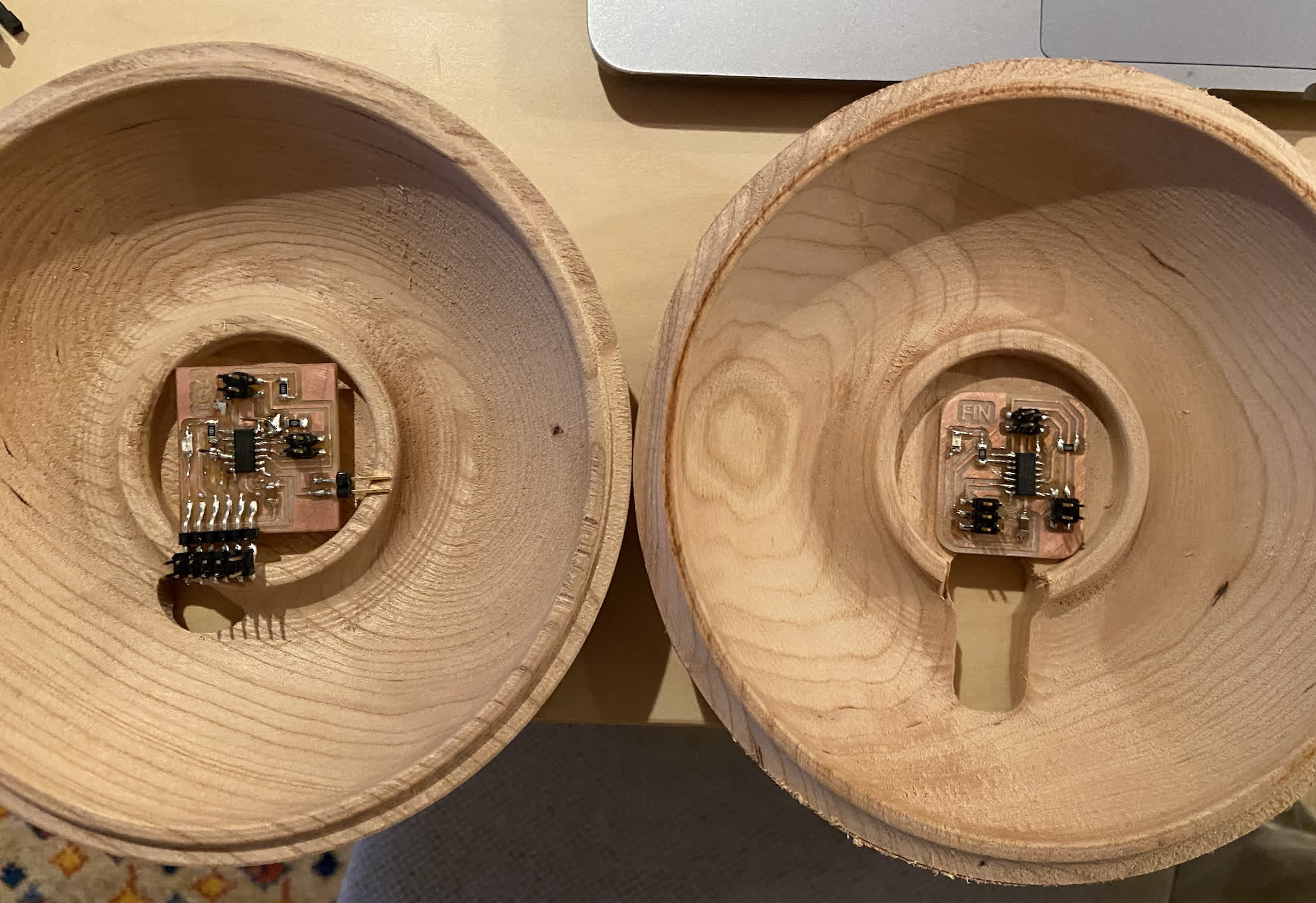
Existing board sitting in the housing:
New board design:
New board fit:
The new board fits well, but I need to shorten the wire lengths between all the components, maybe solder some wiring in place for the final setup. I also need to consider where the phototransistor should sit and hook up the barrel jack as a power source. Beyond that, the physical form of this thing is pretty close to complete.
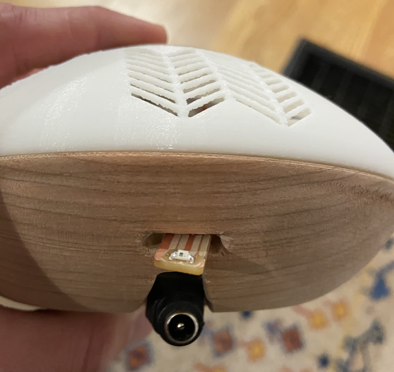
One final consideration/afterthought was giving the phototransistor board a place to exit that would be shielded from the LED's light. I chiseled a small slot over the power cord exit to keep things clean. I would redesign this in CAD to make it a little sleeker, but it works for now.
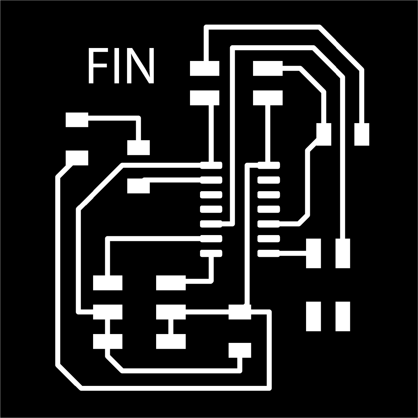
Files:
final_board_traces.png
final_board_interior.png