The Sundown Lamp: A Project Overview
What does it do?
The lamp reacts to surrounding ambient light. In this case, it turns on when the room is dark and turns off when the room is light. Check out this demo and process video to see it in action!
Who's done what beforehand?
This is not an original project. Many people have made light sensitive lamps--most with more complex functionality--but for me this was a good introductory project on number of levels, and it still has a lot of potential.
I found some great examples of past projects that have incorporated one or both of these functions in their project. Some good examples include:
Eva's Fablux Lamp from FabAcademy Barcelona,
Marjo's LED Lamp from FabAcademy Oulu, Finland,
Alex's CastLight project from HMAA 2019.
What did I design? What parts and systems did I make? What tools and processes did I use?
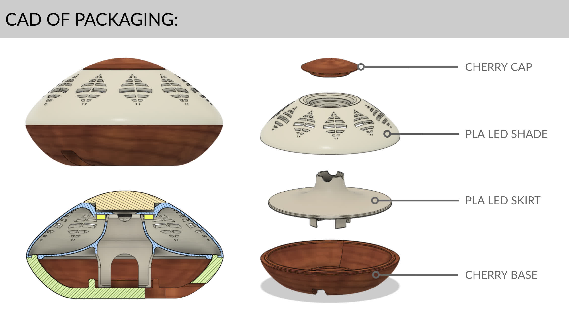
I designed and made everything but the LED ring and the 5V power cord, barrel jack… and the individual board components and the wires connecting the LED to the board. Scroll down to see it all:
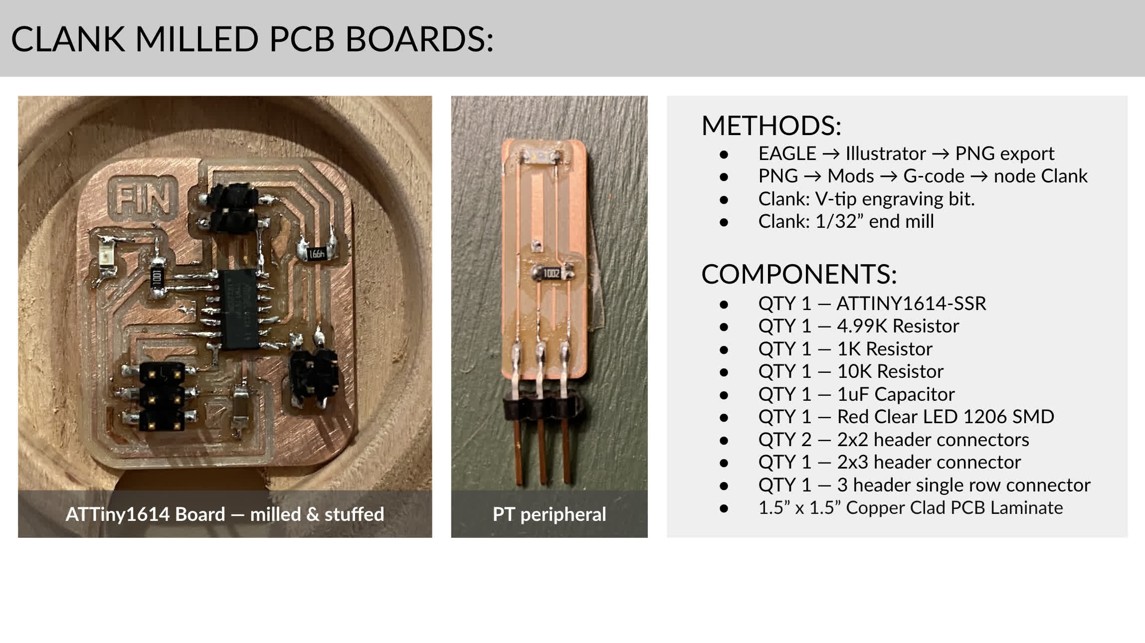
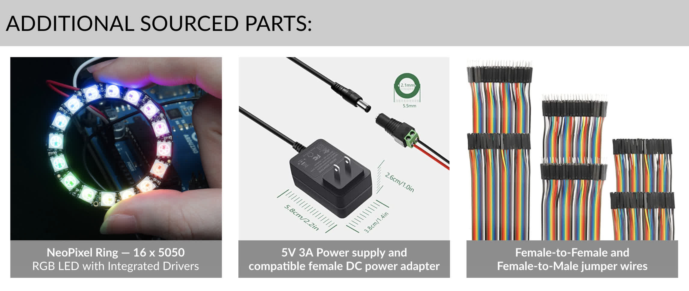
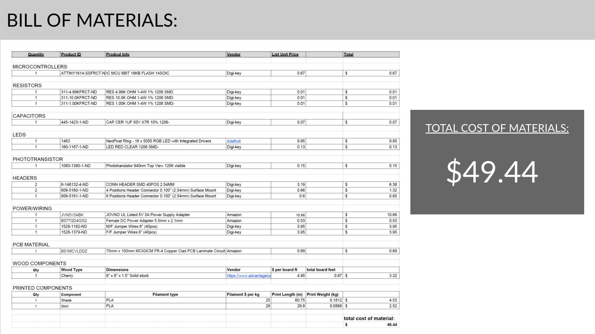
What materials and components did I use, and how much did they cost?
What questions did I answer?
Given schedule constraints and comfort with each technical process, what problem should I tackle first?
In hindsight, I think I prioritized correctly once I had a direction for the physical form of my lamp. I chose to front load the CND and printing work while I had access to campus. While I was confident in my ability to design and fabricate PCB boards at home, I underestimated the difficulty of troubleshooting electronics issues remotely with my still shaky understanding of the subject matter. If I were to do this project again, I would have picked a project at the very beginning. That's the first thing. I would have made progress each week, and would have finished in a more complete state, closer to what I had been accomplish. I would also have put a higher premium on getting rough boards working while I had access to on-campus help. This would also have accelerated the debugging process, which would have accelerated the entire project.
Design & Fabrication Processes:
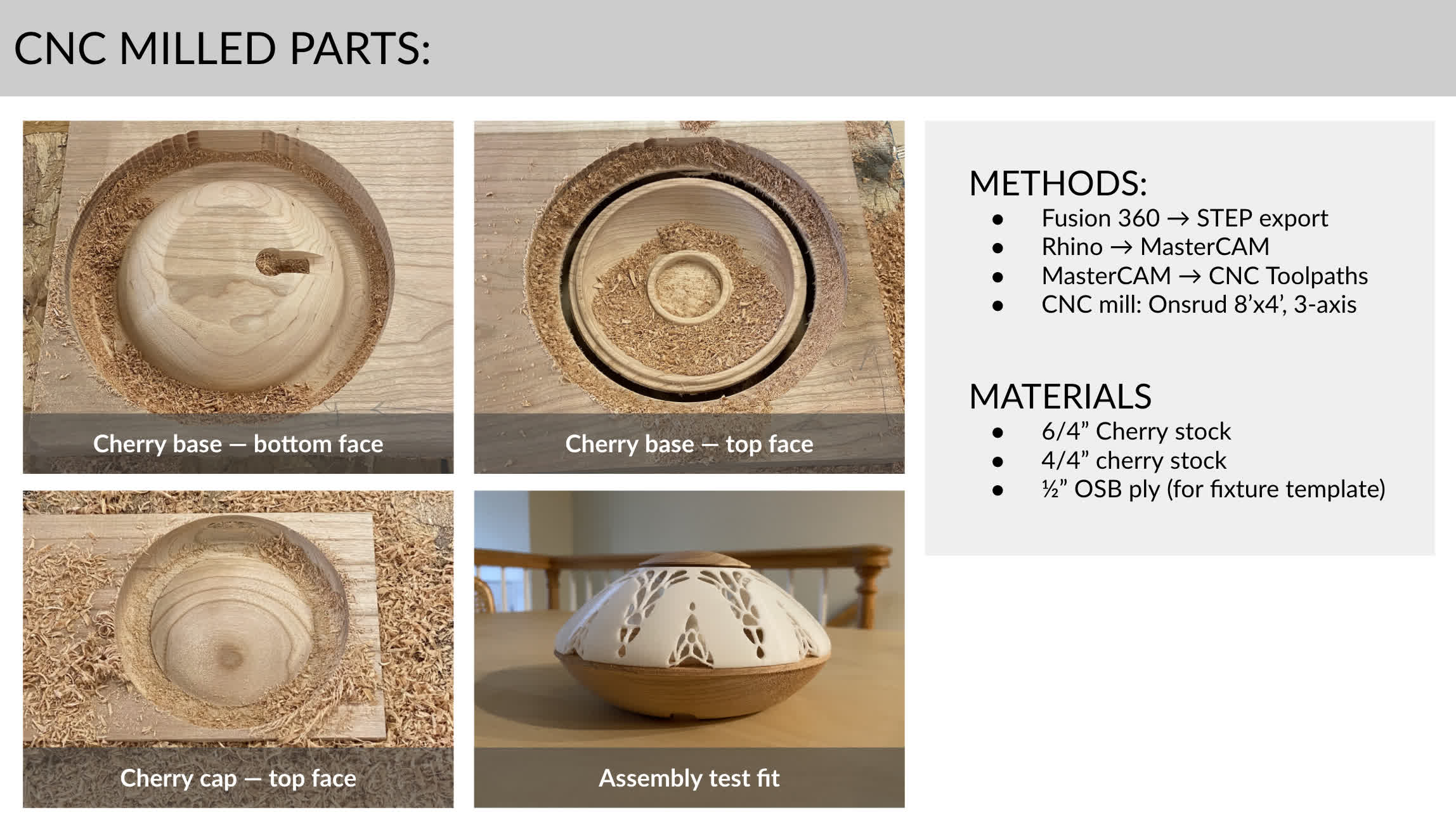
How can you use a 3-axis CNC to surface two sides of a form?
For a smaller piece of stock, making a template to help fixture the piece to the bed will not only hold it in place, but it provides easy registration to ensure that the surfaces will be cut according to plan. A key point in CAD and CAM is to accurately represent the template dimensions. I’d recommend cutting a new template for each new piece to ensure alignment.
What other tools and processes could achieve the same (or better) result?
Concentric circular objects like the ones I created could easily be milled using a lathe. I chose a CNC for a couple of reasons:
1. I wanted to learn how to do this surfacing and flip milling process on the CNC
2. Matching the geometry of the other non-wood components would require a lot of skill and practice on a lathe. Leveraging digital fabrication ensures that the output of the process will exactly match the CAD design--within a certain threshold.
How should you design around end mill constraints while using a CNC?
Know your machine, its bits and design your forms with the tooling in mind. I thought I had done this, but the radius of the ball end mill on the Onsrud was a little larger than the corresponding radius I designed on my shade, so I had to do some post processing to get a reasonable fit. This could have been avoided if I had been more careful to check the tool dimensions as I designed.
Does the packaging design allow for easy reprogramming?
Right now, I need to disassemble the lamp in order ot reprogram the microprocessor. This would have been fine if I had used a wireless chip, but I was unable to get that to work. If I were to design this specifically to be used with hard wiring, I would have accommodated that need in the physical form, but I think further development effort would be focused on getting the wireless to work instead of accommodating that physical design condition.
What tolerances are needed for 3D printed components to fit with wood components?
I used a gap .01in in between concentric components, and that seemed to work fairly well in this case. The fit is a little looser than I'd like, but not much. This tolerance might also be idiosyncratic to each cut or print. I only did two versions, so I haven't sufficiently tested the tolerances for each process yet.
Electronics:
Are the new ATtiny series and NeoPixels compatible? What steps need to be taken for them to work together?
Yes! This was one of the more difficult problems I faced throughout the programming process, but the short answer is they work together. You can check out week10: Output Devices or my Final Project Tracker to see the full journey to making these work, but the high level takeaways that if you are using Arduino, you need to add the MegaTiny Core and Adafruit NeoPixel Libraries, switch your clock speed from 20MHz to 16MHZ, and ensure that you are defining your pixel product as NEO_RGBW + NEO_KHZ800.
How can you tell the NeoPixel to respond to a light level reading from a phototransistor?
Once the phototransistor is hooked up and written into the void setup, your NeoPixel condition becomes a function of the light level readout from your phototransistor. Unlike a simple onboard LED, though, the NeoPixel doesn't turn on or off with a pin reading high or low. Its RGB values should be adjusted for the desired condition based on the sensor input.
What sort of power does this system need?
5V. I used a simple 5V DC adapter I had lying around. Best practices dictate you should use a large capacitor to handle spike or an initial onrush of current.
Can this system be reprogrammed easily as it stands?
As I mentioned in the design & fab section, the product needs to be disassembled in order to access and reprogram the ATtiny1614 board. This isn't difficult, but it is a bit cumbersome and could be improved in a few different ways. As I mentioned, I think looping in a wireless capability to allow for wireless reprogramming.
What worked?
Pretty much everything I have shown so far:
CNC milling 2 sided wooden parts.
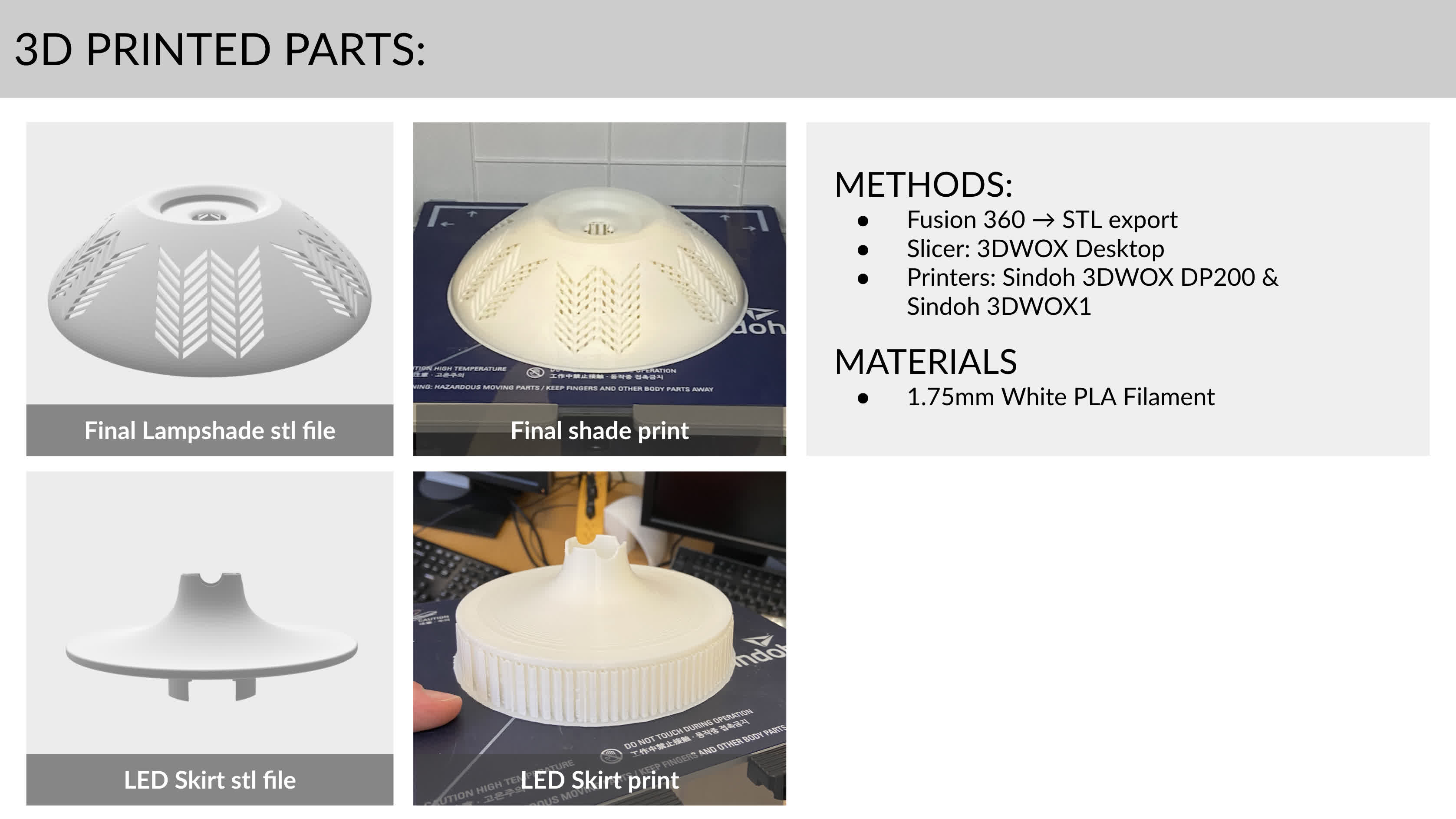
3D printing a shade for LED diffusion.
3D printing an internal LED mount/skirt to conceal electronic components.
Programming the NeoPixel to respond to a measurement from a phototransistor.
Powering the programmed PCB and LED with a 5V wall adapter.
What didn't work?
Most of the above listed processes did not work at some point, but there a lot more that got cut in triage. At the outset, the project had been a bit more ambitious, including interactions like the one displayed below,
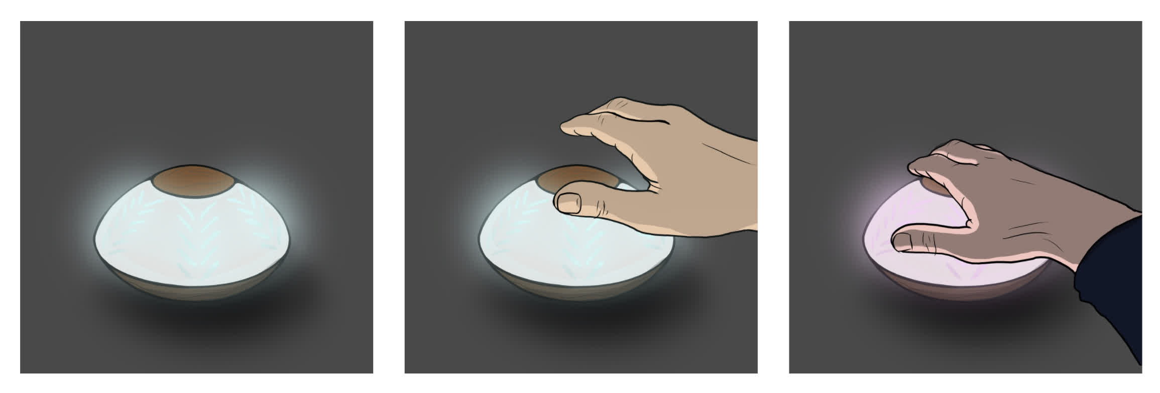
but the following list was cut to meet the project deadline. Instead of saying these were failure or that they didn't work, though, I'd prefer to designate this list as "future work":
Concealed capacitive touch sensor to change light color.
Wireless communication between the lamp and a computer.
A phone app interface to control the lamp, change color, light sensitivity, etc.
Network a second lamp to mirror the first. First hardwired, then wireless.
Program the LED to respond to real-time sunlight data. The brightness exists as a function of where the sun is in its journey across the sky.
How was the project evaluated, and what are the implications?
As I said at the beginning, this project is not ground breaking. It simply represents a basic integration of many of the skills we covered in this class. While having to scope down the complexity of the project was frustrating at times, I got the lamp to a workable place for this assignment, and I learned a little more about how to approach a project like this--namely one that includes many technical processes that are unfamiliar to me at the outset. I chronically underestimated the time and effort each new skill would require, and as a result, there were moments when I spiraled in the wrong direction. Where I did succeed, however, was timing the use of the Onsrud. If I had not used that when I did, I would have been limited in my ability to create the form I wanted from the material I liked. What I failed to plan for, however, was how difficult troubleshooting and debugging is in a remote setting. The communication process requires a lot more time, energy and creative communication from both parties for it to be effective, and at this point, remote debugging can't hold a candle to an in person session with a TA or instructor.
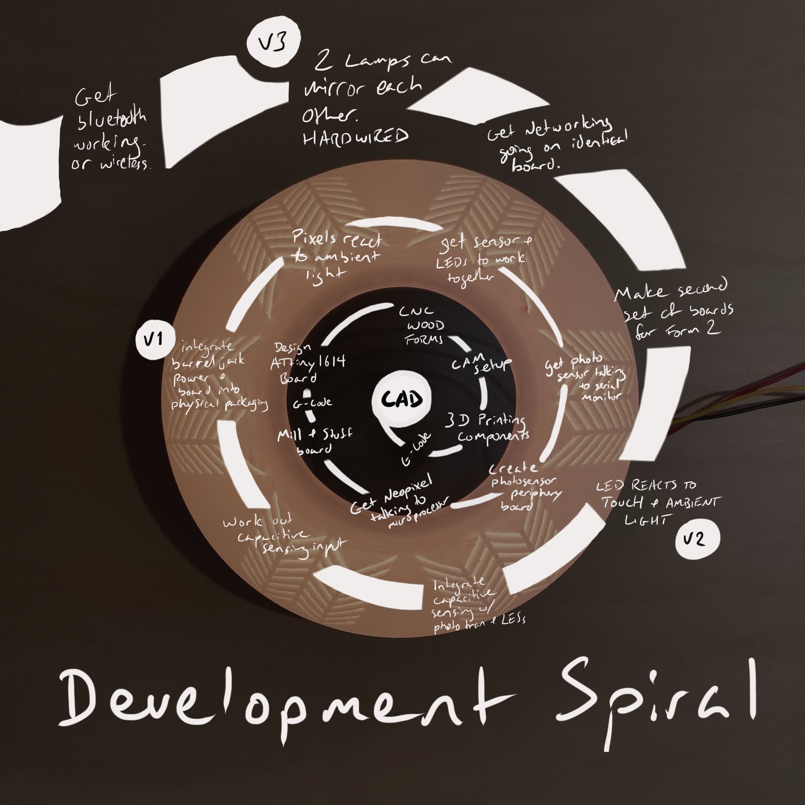
So in general, I think the implications of this project are primarily those of personal development. I have a path forward for this project, an understanding of the methods, tools and components required to pursue that path, and a development spiral for taking it on in managable chunks.
In a greater context, this class and this project demonstrate how a hands-on learning experience like How to Make Almost Anything can and should be tailored to a remote setting. The implications to that end are much greater. This class is possible without access to a lab, but a larger portion of the planning--both from a staff and faculty perspective and from a participating student perspective--needs to happen at the outset, accomodate lead times, spatial constraints and technology breakdowns. More effort will be required in regard to asynchronous communication. None of this is impossible, but it presents interesting challenges and a reframing of what projects should include. Is the goal of the class to learn to individually operate machines and fabricate devices? Or does the class raise the idea and challenge to its students of how we might leverage the distributed digital fabrication network to produce our plans. Is the import placed on the physical making? Or is it placed on how to communicate with the people and machines that will be producing parts?
Files:
BOM.xlsx
Sundown_Lamp_CAD.f3d
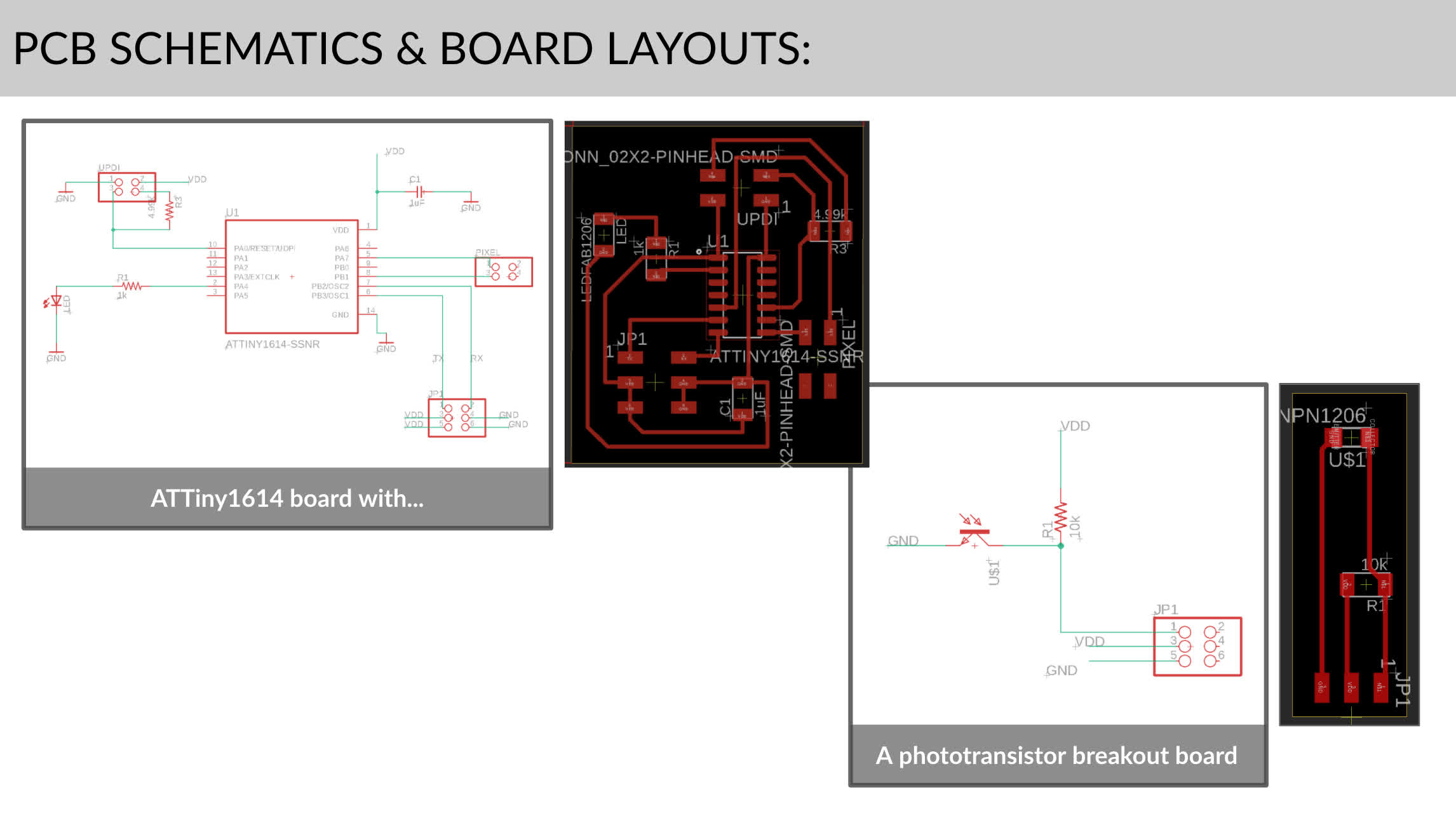
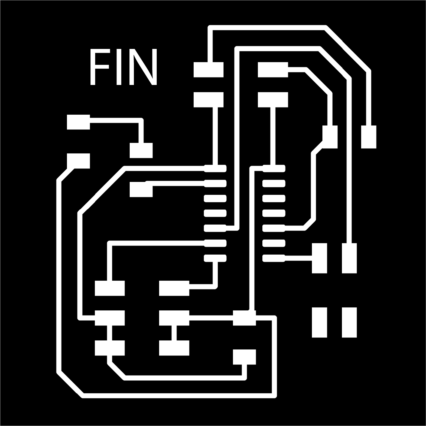
final_1614_board.sch
final_1614_board.brd
final_1614_board_traces.png
final_1614_board_interior.png
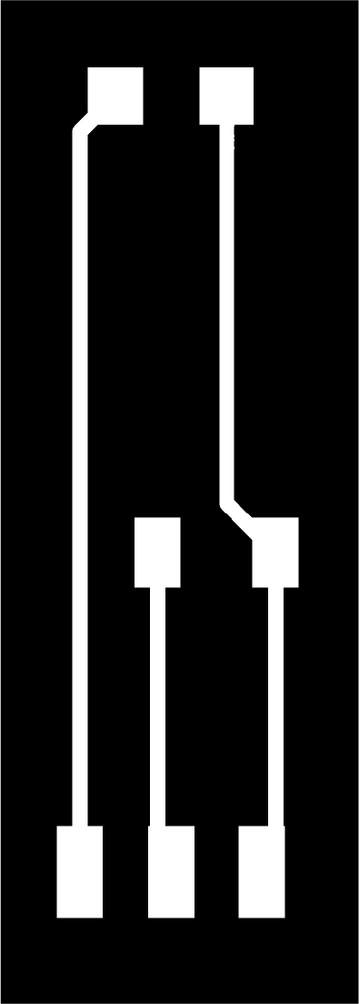
photosensor_breakout.sch
photosensor_breakout.brd
photosensor_breakout_traces.png
photosensor_breakout_interior.png
example_light_sensitive_neopixel.ino