Week 12: Interface & Application Programming
Individual Assignment: write an application that interfaces a user with an input &/or output device that you made.
The last few weeks have been a bit of a debugging mess. Things just aren't working like they should be, and I think a large portion of the issues I've encountered have stemmed from me trying to mix and match approaches I've seen online to boards I already have on hand rather than recreating boards from scratch to match those methods. I kind of equate it to trying to play a new piece of music on an instrument I am still learning. I'm still learning how the chords map onto the fingering patterns, and I need to do that before I can start improvising. So with that in mind, I thought it would be a good idea to just get acclimated to this assignment before trying to wrestle an wrestle an interface onto one of my boards.
Learning Processing:
I am becoming more comfortable with Arduino, and I want to take advantage of that comfort. Neil mentioned that if we like Arduino, we would like Processing. "They share very much the same spirit look and feel." I can echo that. The interface looks familiar, which is promising.
As usual, I reached out to my fellow section mates before setting out, wanting to learn from any progress they had made on their own this week. Luckily Omar had already made some good strides, and he directed me to a very good beginner tutorial for using Arduino and Processing. The full tutorial is really straightforward and helpful, but the video is a step-by-step walkthrough to building the simple LED on/off interface, and I would definitely recommend true beginners like me should start by just following through the video.
This is clearly stated in the tutorial, but to do this example you need the following:
1. Arduino(1x) -- the example uses a Nano, but any will do
2. Generic Breadboard (1x)
3. LEDs (3x) -- 1red, 1yellow, 1blue
4. 100 Ohm Resisters (3x)
5. Jumper wires (4x)
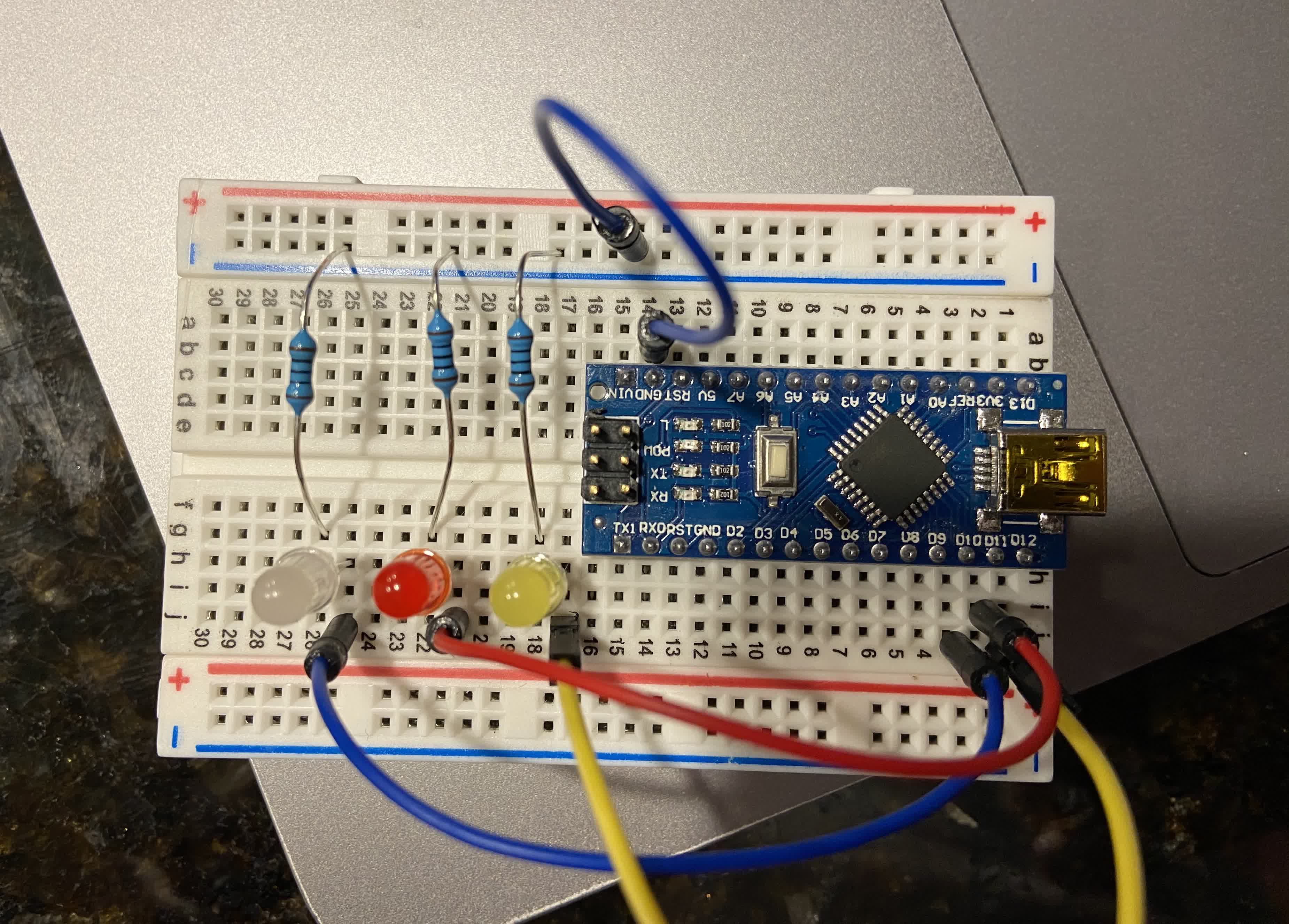
This is the schematic from the tutorial incase it's hard to see where the wires are connecting in the picture above:
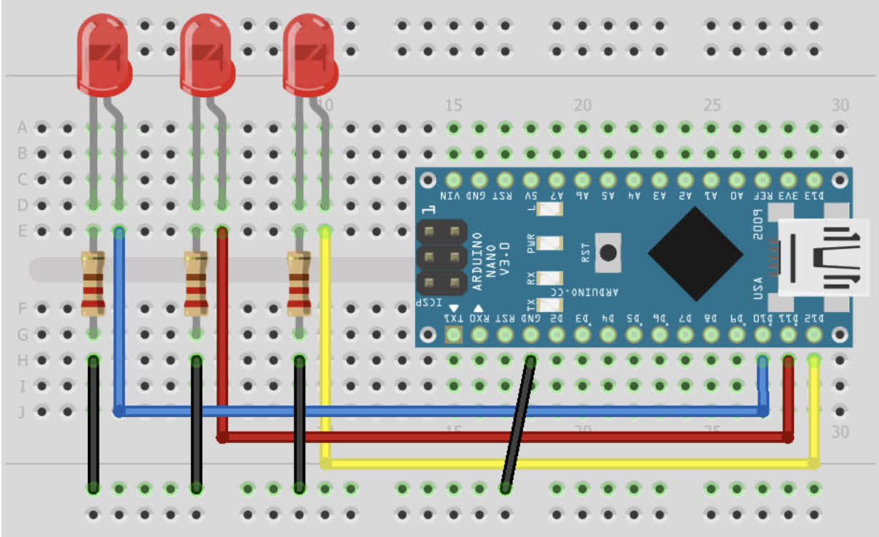
The basic process here is simple. Build a sketch in Processing to create the look and layout of the interface as well as how it responds to interaction. In this case, the interface spits an assigned char value out to the arduino board according to the button that has been clicked. You then build the Arduino sketch to read the char value coming in from that clicked button and respond by lighting the corresponding LED.
Processing Code:
              import controlP5.*; //import ControlP5 library
              import processing.serial.*;

              Serial port;

              ControlP5 cp5; //create ControlP5 object
              PFont font;

              void setup(){ //same as arduino program

              size(300, 450);    //window size, (width, height)

              printArray(Serial.list());   //prints all available serial ports

              port = new Serial(this, "/dev/cu.usbserial-14510", 9600);  //i have connected to /dev/cu.usbserial-14150. This will change depending on the port you are using.

              //lets add buton to empty window

              cp5 = new ControlP5(this);
              font = createFont("calibri light bold", 20);    // custom fonts for buttons and title

              cp5.addButton("red")     //"red" is the name of button
                .setPosition(100, 50)  //x and y coordinates of upper left corner of button
                .setSize(120, 70)      //(width, height)
                .setFont(font)
                ;

              cp5.addButton("yellow")     //"yellow" is the name of button
                .setPosition(100, 150)  //x and y coordinates of upper left corner of button
                .setSize(120, 70)      //(width, height)
                .setFont(font)
                ;

              cp5.addButton("blue")     //"blue" is the name of button
                .setPosition(100, 250)  //x and y coordinates of upper left corner of button
                .setSize(120, 70)      //(width, height)
                .setFont(font)
                ;

              cp5.addButton("alloff")     //"alloff" is the name of button
                .setPosition(100, 350)  //x and y coordinates of upper left corner of button
                .setSize(120, 70)      //(width, height)
                .setFont(font)
                ;
                }

              void draw(){  //same as loop in arduino

                background(150, 0 , 150); // background color of window (r, g, b) or (0 to 255)

                //lets give title to our window
                fill(0, 255, 0);               //text color (r, g, b)
                textFont(font);
                text("LED CONTROL", 80, 30);  // ("text", x coordinate, y coordinat)
                }

                //lets add some functions to our buttons
                //so whe you press any button, it sends perticular char over serial port

                void red(){
                  port.write('r');
                }

                void yellow(){
                  port.write('y');
                }

                void blue(){
                  port.write('b');
                }

                void alloff(){
                  port.write('f');
                }
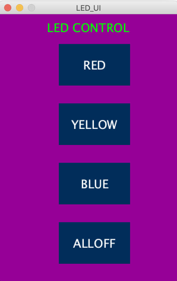
This sketch should produce a GUI that looks like this:
Corresponding Arduino Sketch:
              void setup() {

                pinMode(10, OUTPUT);   //set pin as output , blue led
                pinMode(11, OUTPUT);   //set pin as output , red led
                pinMode(12, OUTPUT);   //set pin as output , yellow led

                Serial.begin(9600);    //start serial communication @9600 bps
                }

              void loop(){

                if(Serial.available()){  //id data is available to read

                  char val = Serial.read();

                  if(val == 'r'){       //if r received
                    digitalWrite(11, HIGH); //turn on red led
                    }
                  if(val == 'b'){       //if b received
                    digitalWrite(10, HIGH); //turn on blue led
                    }
                  if(val == 'y'){       //if y received
                    digitalWrite(12, HIGH); //turn on yellow led
                    }
                  if(val == 'f'){       //if f received
                    digitalWrite(11, LOW); //turn off all led
                    digitalWrite(12, LOW);
                    digitalWrite(10, LOW);
                    }
                  }
                }
Quick note: the UI window will only open if the serial port is the right one. I accidentally switched the usb port I was using on my Mac, and I kept getting errors until I realized the port I selected did not match the port I had called out in the sketch:
Once I got past that snag, the interface and LED setup worked the way it was supposed to! After a couple weeks of things really not cooperating, it was a nice, albeit small, victory.
Files:
Arduion Code
Processing
Creating an interface for my input board:
With the example handled, I wanted to turn my focus to creating an interface for my input board that had housed a working onboard phototransistor. Because that board had been working well before, I thought this would be a lighter lift than trying to get my capative sensor working or the neopixel output board working well enough to respond to an interface.
But following in the tradition of all my other boards, this 412 input board that had previously been working fine decided to bug out on me at the opportune moment.
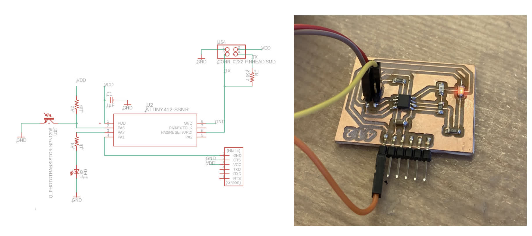
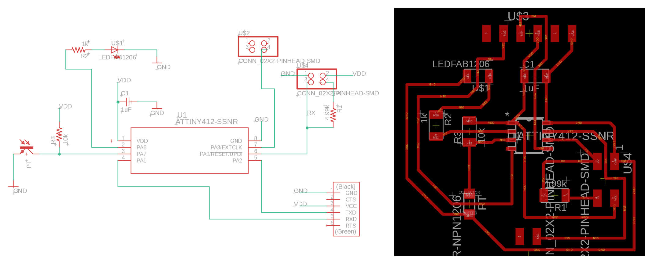
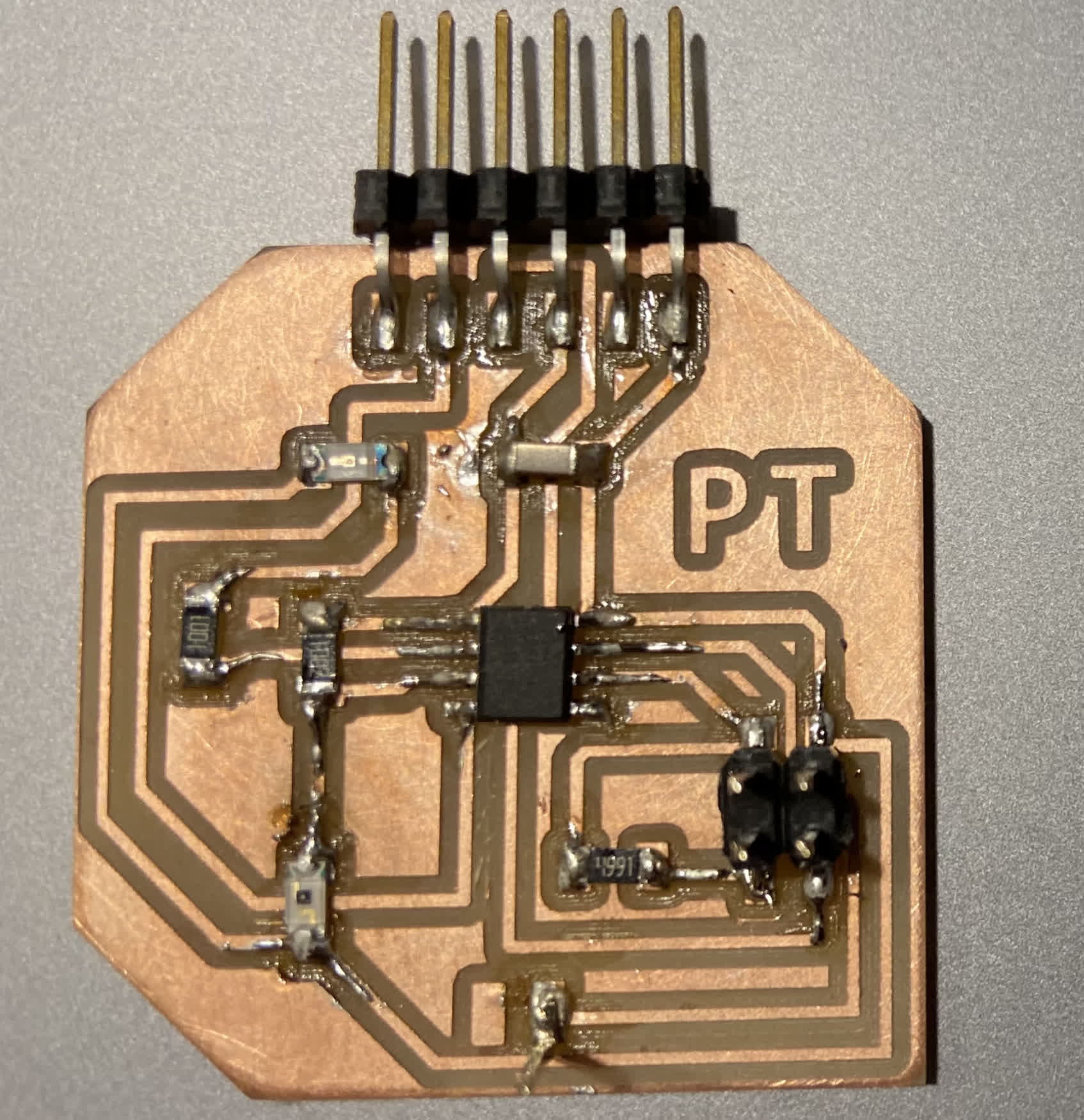
For context: My original board schematic looked like this. It's a little janky and breaks some conventions for wiring to the ftdi pin header, but it worked as it should. Here is the schematic and board at week8:
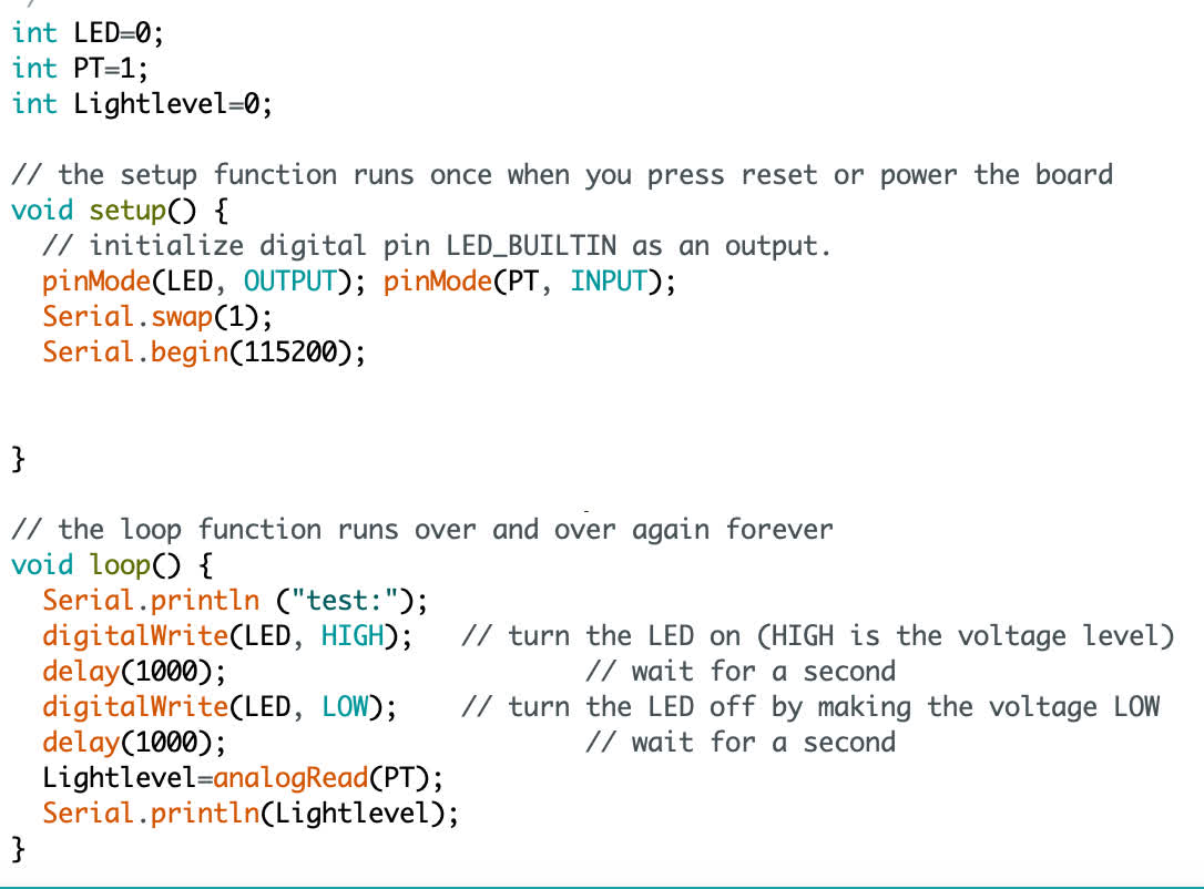
I had some very simple code to just get a test readout to make sure the sensor was working. It looked like this:
And the readout on the serial monitor gave me "test" and a light level value as intended:
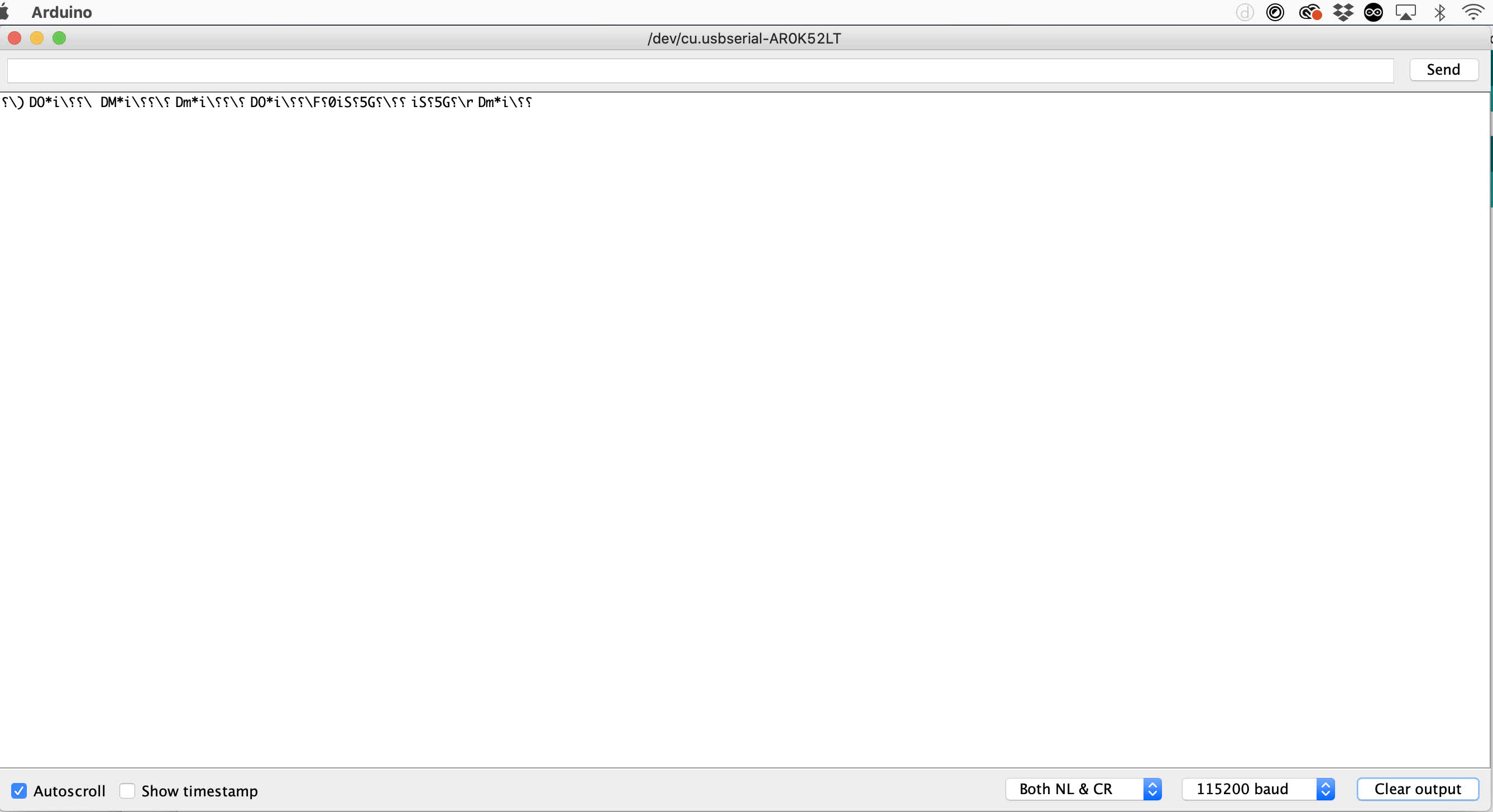
In trying to get my networking assignment to work, I doctored the board a bit to give me a Tx connection that did not previously exist on the board. I had no trouble programming the board for a simple call and response, but when I ran the same test code again to get the phototransistor talking, my readout became nonsense characters.
My theory is that there is something up with the wiring. Jake mentioned that lowering the baude rate may help deal with faulty wiring, so I'll try that. Beyond that, I'll bring out the oscilliscope to test the signal. If that doesn't help, I'll make another board, but I'd like to avoid that if possible.
I broke it out and tested some pins, but I'm still a little shaky on how to use and read the oscilliscope, so I couldn't quite figure out whether it was giving me what I was supposed to be getting. I had been planning on making some new boards anyway, and since I had already redesigned the phototransistor board in Eagle to give me the necessary Tx and Rx connections, I decided to load that into the queue.
I thought this would be a quick job, but, naturally, Clank decided to act up. It was giving me different depth and width cuts, so I tighted screws, pulleys, belts, and then I refaced the bed for good measure. 2 hours later, I ran my new boards, and got good results. Clank is still a little shaky on diagonal cuts, so I think one of the pulleys may still be loose, but the results were good enough to use.
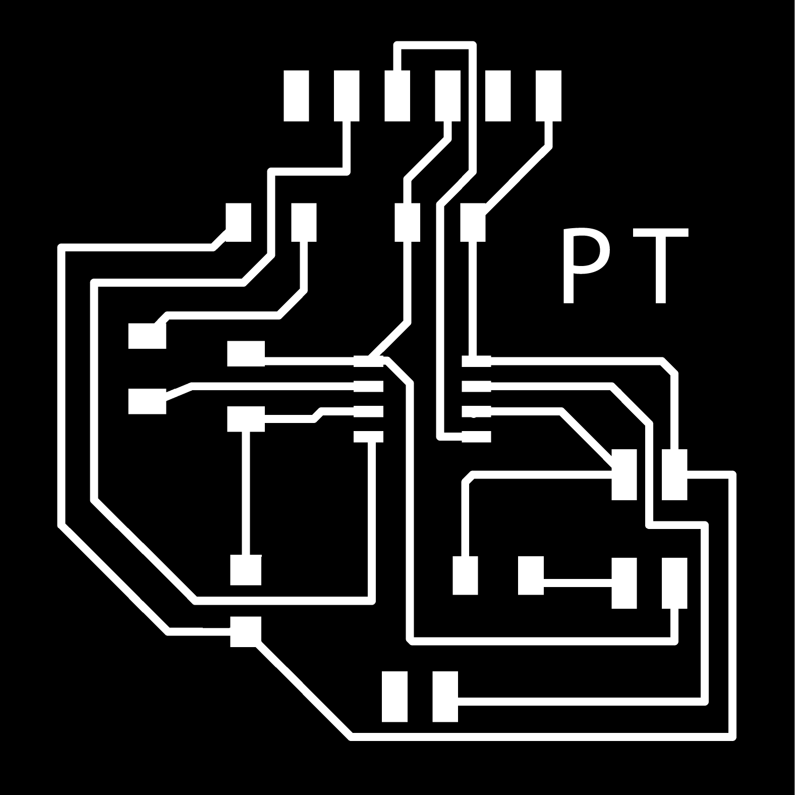
Schematic, Board layout, and final milled & stuffed board:
I thought the board looked good and should work, so I ran my test program again. Careful to make sure the variables corresponded to the correct pins and that Serial.swap came before Serial.begin. Here's the code:
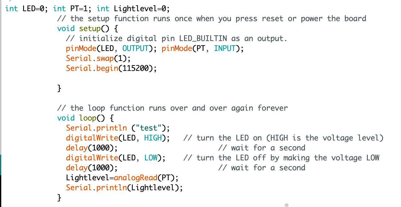
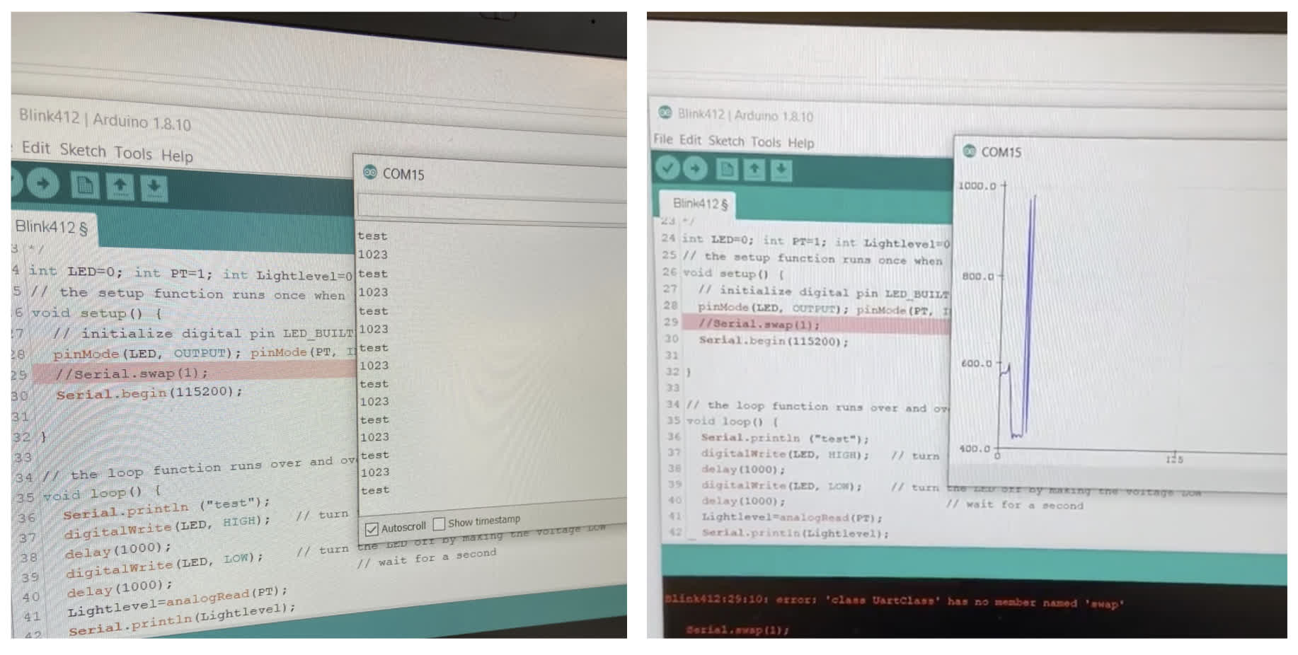
But when I ran the test, I got the same nonsense output:
Needless to say, I was pretty frustrated at this point. I tried adding a new phototransistor and changing the baud rate. Neither trick worked.
Eventually I went back to the "Tool" setup in arduino to toggle with those settings. I realized that the clock rate was set to 16MHz, so I changed it to 20MHz, ran the code, opened the serial monitor, and....
I celebrated for a moment, and then realized I was just back to square one, having spent half a day to get back to where I had started. Oh well. We forge on!
Arduino, Processing and my Phototransistor Board:
I went back to the Google machine to learn a bit about how to make these programs talk about the information my board is so dutifully retreiving. There are a lot of good tutorials about how to visualize sensor data using Arduino and Processing together. Conceivably, if you already have your board spitting out information into the serial monitor, you should be able communicate data to Processing. You Arduino code just needs to read a sensor value from an analog pin--perform an analogRead() function. The harder trick is setting up the Processing code to present that sensor data in some form.
I watched a few videos and read few tutorials, and I found that this particular tutorial for graphing sensor values via a serial output was a good start for me. It breaks up the code into chunks and describes what each aspect of the code is doing. It does get a bit confusing as you are ordering these chunks, but eventually I got something running that produced the color and look of the intended version.
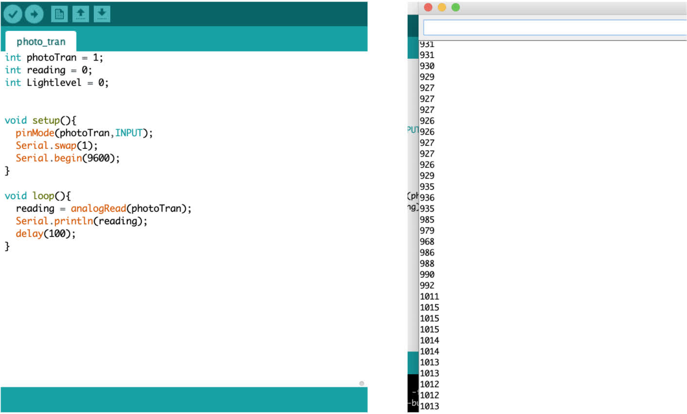
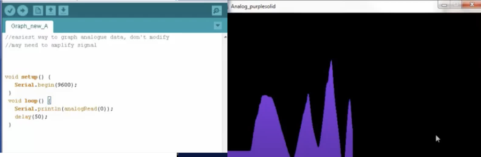
Below is the first version of my Arduino code with the serial monitor shown to its right. You can see the values change based on the sensor's light exposure.
Next I have the Processing code, which is based on the code from the tutorial. The live graphic display is shown to the right. Compared to the example the tutorial shows, the shape of the curve is not quite as dynamic. I will need to figure out if this is an effect of the way I built the Arduino code or if the values and dimensions of the Processing window are too large to display the small data fluctuations at a higher resolution.
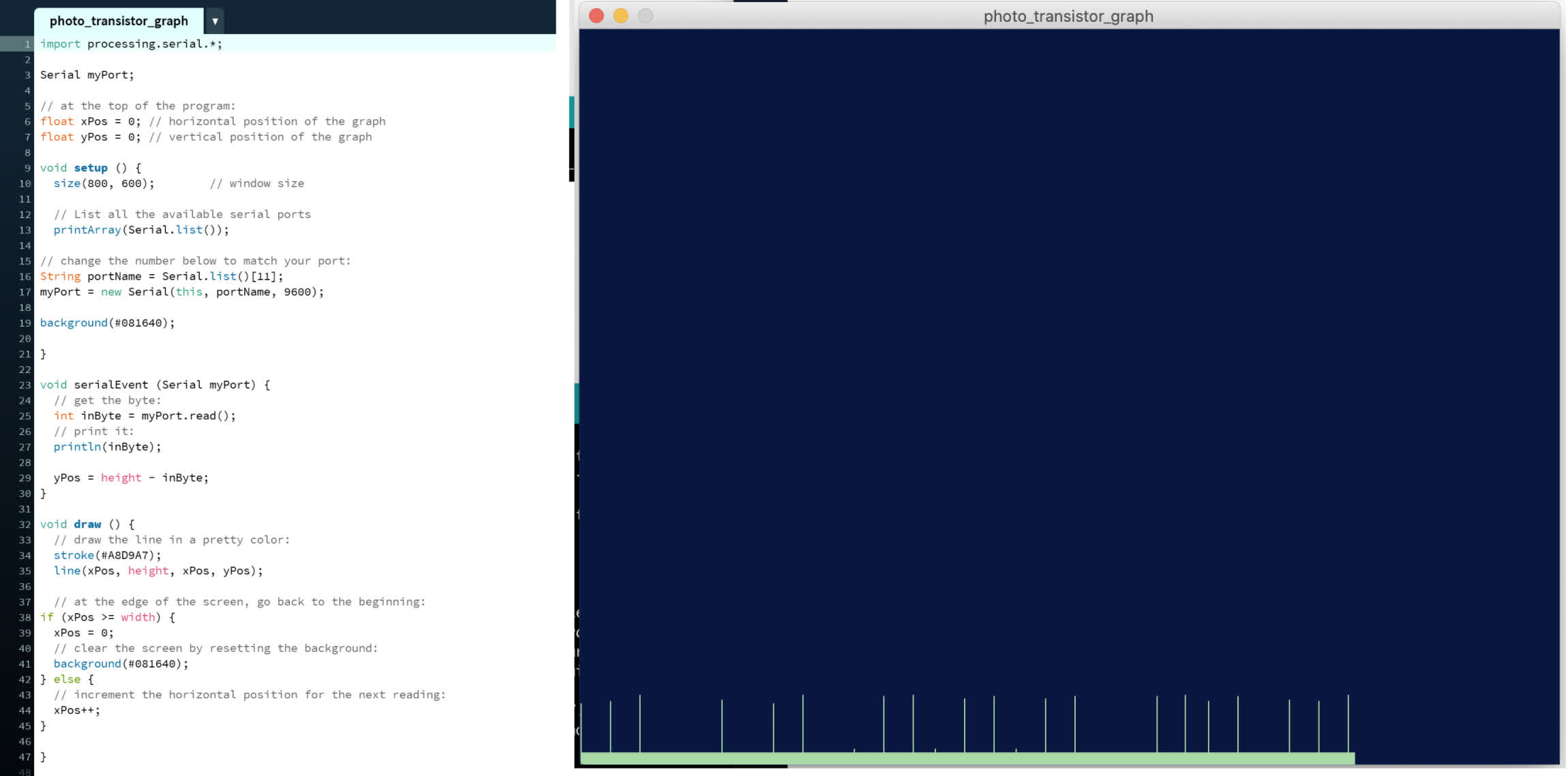
Here is the live video of the graph:
I think it's likely an artifact of the Processing code, not the Arduino. This Youtube example has equally simple Arduino code for its sensor data, and that drives a much more dynamic graphic. See the example below:
Now that I successfully have a sensor board talking to Arduino and Processing, the challenge is creating a more readable interface. Ideally, I'd like to have both a light level display and an on/off toggle for the final project, but we'll see how it all shakes out in the coming week. One will likely get excised in triage.
Files:
412_photo_tran.sch
412_photo_tran.brd
412_photo_traces.png
412_photo_interior.png
412_photo Illustrator File
Arduino_photo_transistor
Processing_photo_tran_graph
Arduino_photo_transistor