Assignment: Design, cut, process, & assemble something big
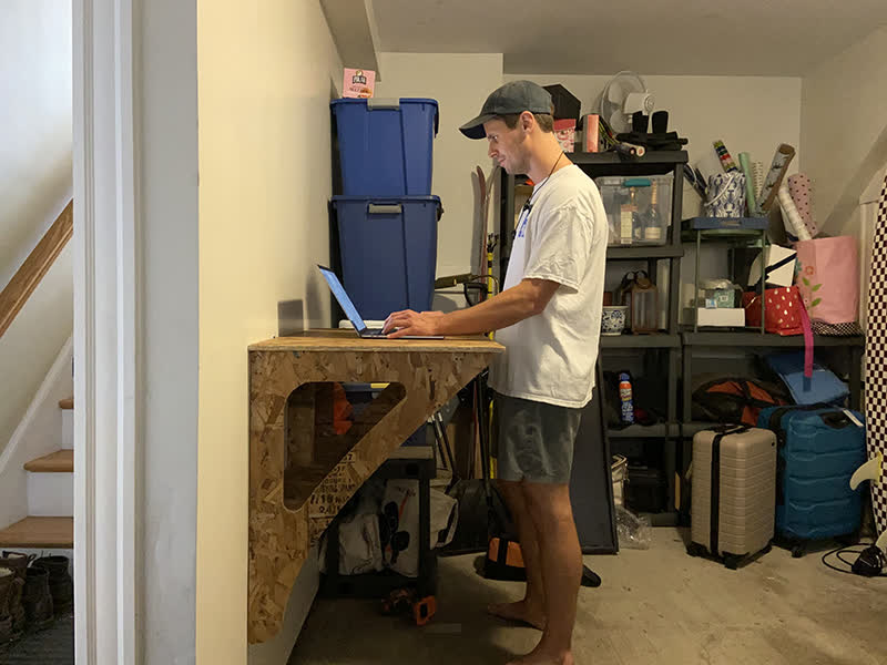
I have been working at my dining table since March. My fiance has tolerated this for more digital work, but as my HMAA assignments have become more physical, they are taking over...
So, I need a work surface that is not my dining table. Why not knock out two birds with one stone and "make something big" to work on?
Design Iteration and Final CAD:
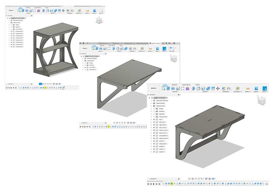
Using Fusion360, I built a few potential concepts, iterating my way to my final design.
I originally thought my third design would be my final. After measuring the OSB in the shop against the parameter I set for material thickness, I realized I needed to change the thickness.
When I plugged in a new value for the ply thickness, the model tore itself apart. I tried to troubleshoot, but I eventually determined it would be faster for me to rebuild the model. The geometry was simple enough,
and I determined that the constraints are best set in teh sketch phase. When I began pushing and pulling the body outside of the sketch, I messed with the already constrained geometry in a way that it didn't like.
My fourth model is similar to the third, though the perpenticular support is a little longer. Roughly 30" in case I wanted to mount it at a normal table height instead of a standing height.
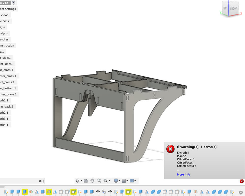
In this model, I was very deliberate in how I set my parameters and maintained my constraints. I checked how the model would react after I added each new body. While a bit tedious, it gave me flexibility to adjust
the material thickness, and therefore the joint dimensions, prior to machining the final piece.
Parameters I set for model 4. Material thickness was about 0.438" or 7/16"
Parameters I set for model 4. Material thickness was about 0.438" or 7/16"
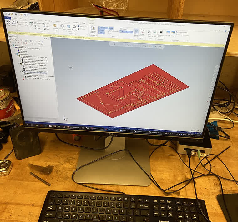
I need to add a few photos of the steps between completing the model and setting up the machining file in MasterCAM. I found a really great new feature in Fusion that is still kind of in the
testing phase. It's called "arrange," and it automatically nests and optimizes your component layout for sheet good machining. Awesome feature. Still a bit buggy though. After that, because the Arch shop tools are
all set up for Rhino, I exported a dxf from a projected sketch file in Fusion. Then import to Rhino, add points to the interior corners to create the dogbones, and export the file to MasterCAM. This photo shows the
toolpath set up for three separate operations: drilling dogbones, cutting small pieces and interior pieces with a finer 1/4" bit (2 passes), and a single clearing pass with a 3/8" bit.
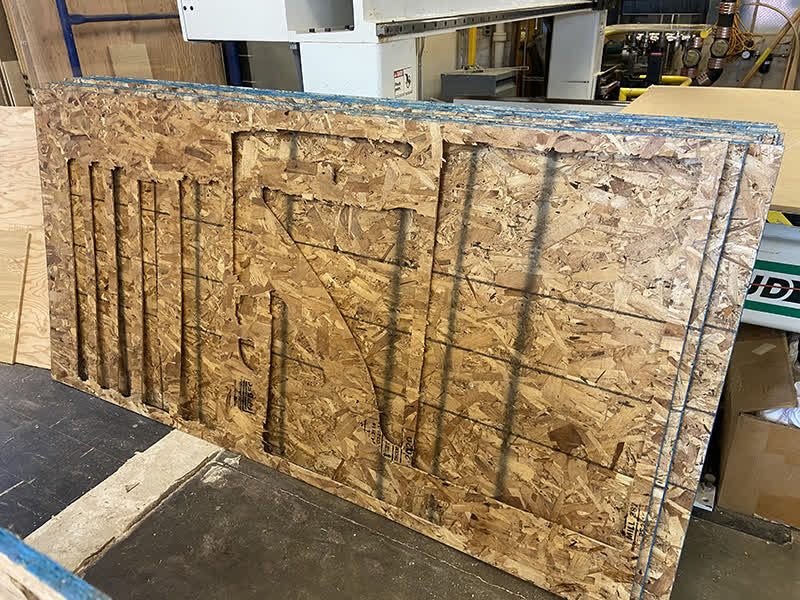
Time to Machine this OSB:
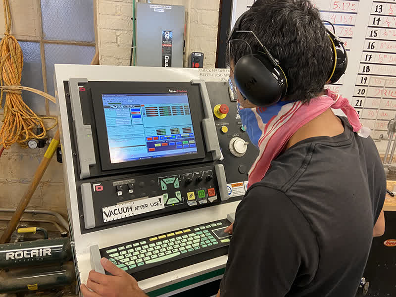
Zain bringing my CAM to the Onsrad.
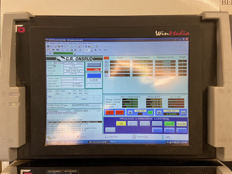
Onsrad Interface. Set and running
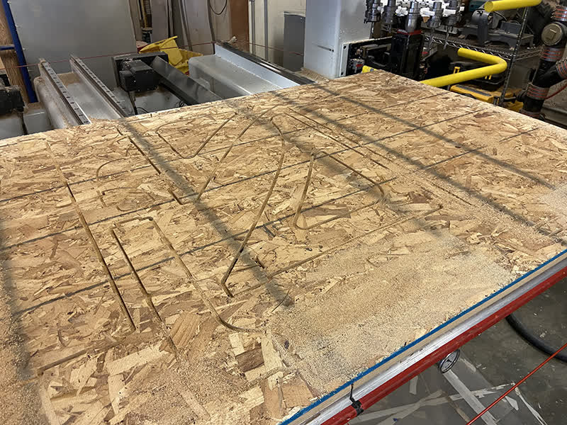
All cutting complete. No parts destroyed. So far, the machining is a success.
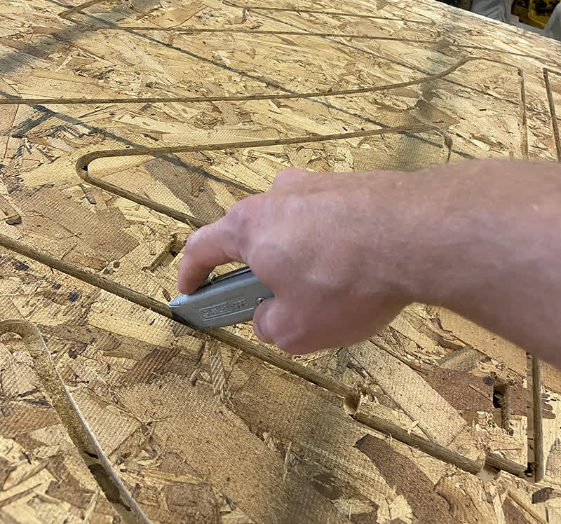
Slicing the onion skin before removing the components from the bed.
Offcut piece. Fairly well optimized to reduce waste, but I could have done better. This piece is now virtually unusable.
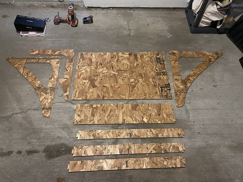
Assembly and Installation
All components successfully transported to their final home and laid out and ready for assembly.
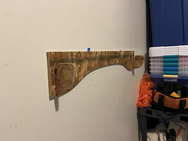
And first we mount the wall bracket with screws. The teeth of the bracket function like a french cleat style wall mount system.
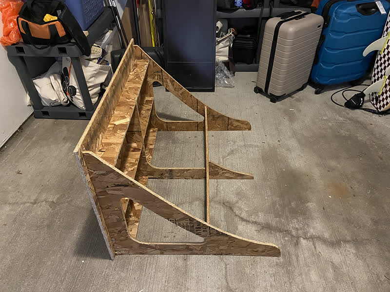
ASSEMBLY TIMELAPSE!
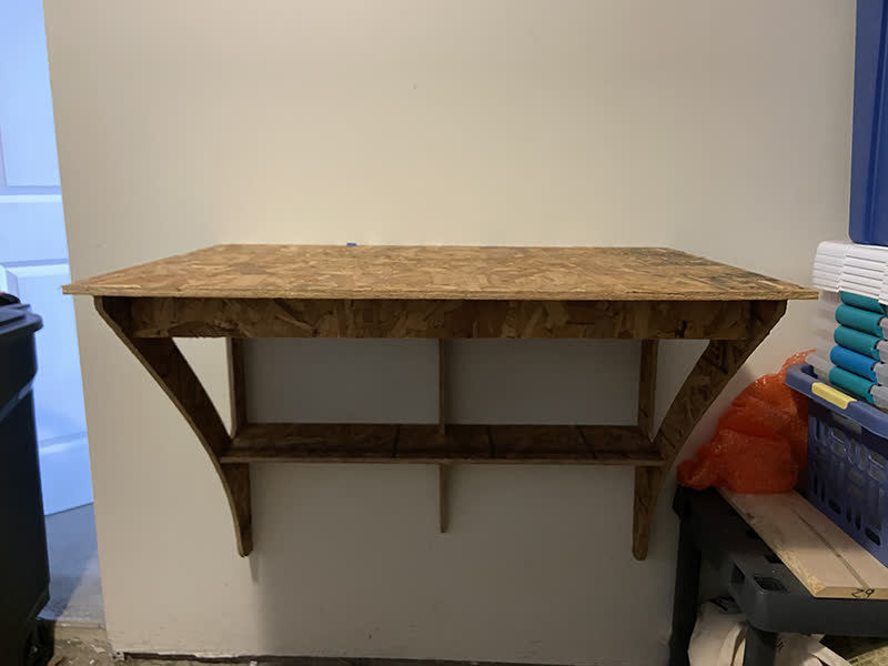
Static picture of assembly. Pre-mounting.
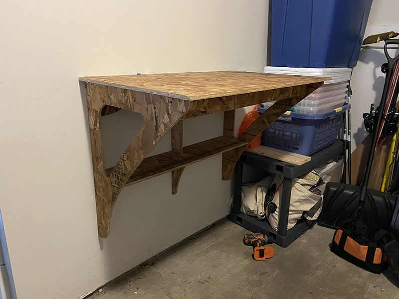
Mounted 1.
Mounted 2.