Week 6: Electronics Design!
Group Assignment: Use test equipment to observe the operation a microcontroller circuit board.
Group assignment pageIndividual Assignment 1: Design and Make a helloworld circuit board
I broke bits, tore up copper, and otherwise wrestled with Clank into this weekend, but once I thought it was in a usable state, and I had a good handle on the Clank workflow, it was time to spin myself up on the next assignment.
Eagle Round 1: ATTiny44 board
I rewatched the class and recitation videos to figure out where to start. It seems like both KiCad and Eagle have their advantages and drawbacks. I decided that reviewing prior years' cohorts and their experiences this week would give me a good sense of which would be better for me. Given my lack of electronics experience, I looked through the arch sections from past years to find my people. I found the documentation from Marianna and Rafa Rafa to be pretty helpful. After canvasing these resources, I downloaded both softwares and poked around in them to get acquainted. I decided to go with Eagle for a couple reasons: 1. I like that it can integrate with Fusion360. 2. For some reason I found the process of adding libraries to Eagle a little bit easier. So, I chose Eagle. Now for the fun part: choosing what to make.
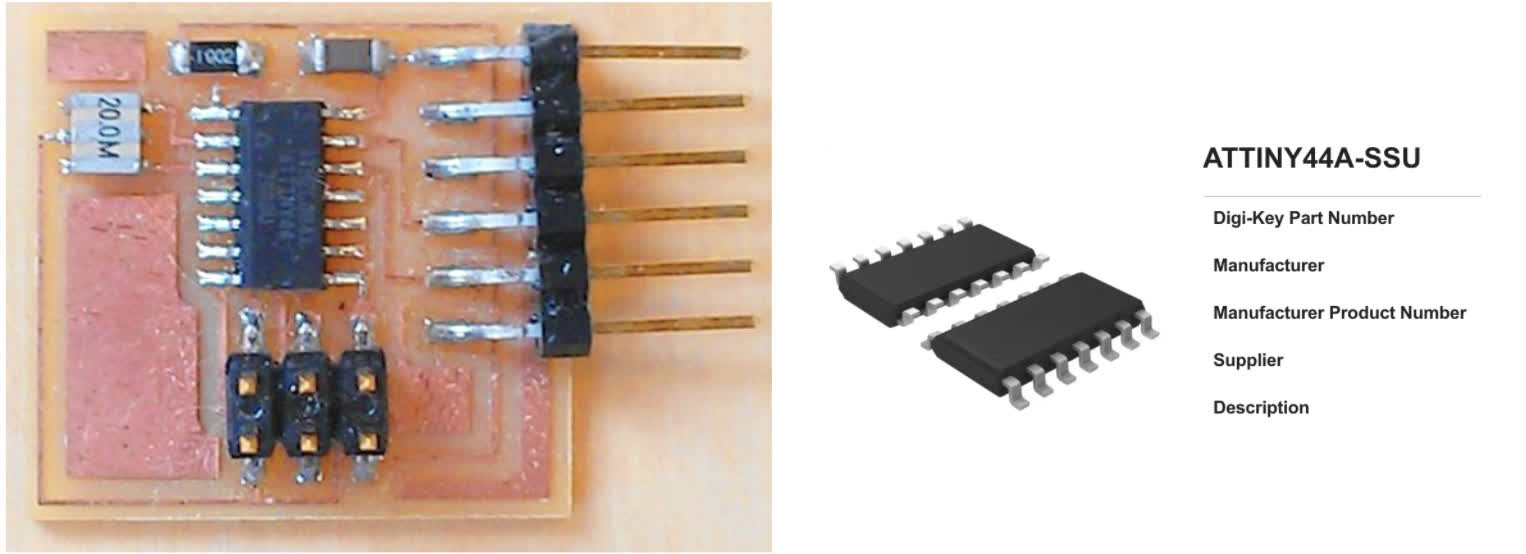
Given how out to sea I felt while trying to learn anything about electronics, let alone a new CAD software, I thought it would be helpful to follow the instructions of those who came before me. The ATTiny44/45 board seemed to be a popular choice in the past years, so I decided to use that as my jumping off point. You can see the board, the chip spec, the schematics and the board layout (without traces) below.
Eagle Round 2: ATTiny1614
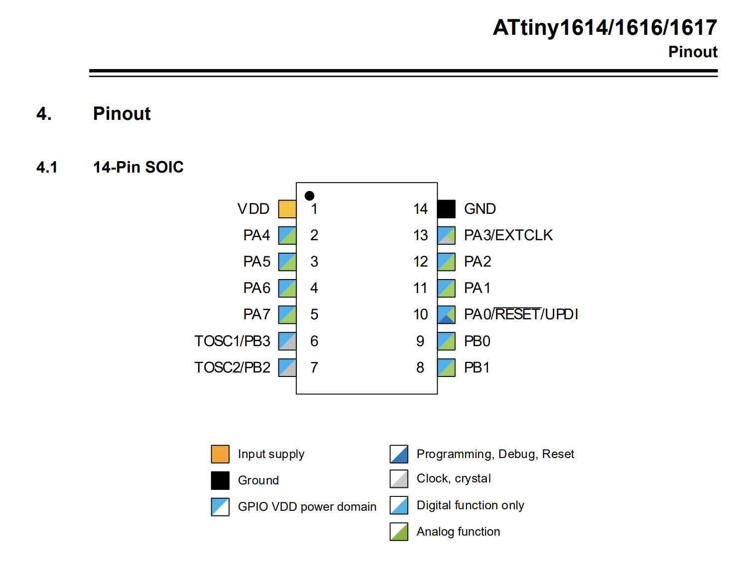
Ok. First things first. The Fab Eagle library does not have the ATTiny1614 footprint. Neither does AdaFruit or Sparkfun. You can find and download it here Everything else I needed seemed to be in the fab library. Now, the data sheet:
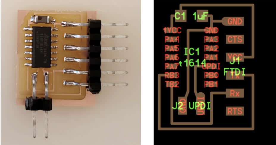
My reference board for this project is Neil's ATTiny1614 Helloworld board. See below:
But.... I needed to add a Button and an LED. So we had a little work to do in Eagle to set that up. Luckily, Anthony's tutorial was a good guiding hand.
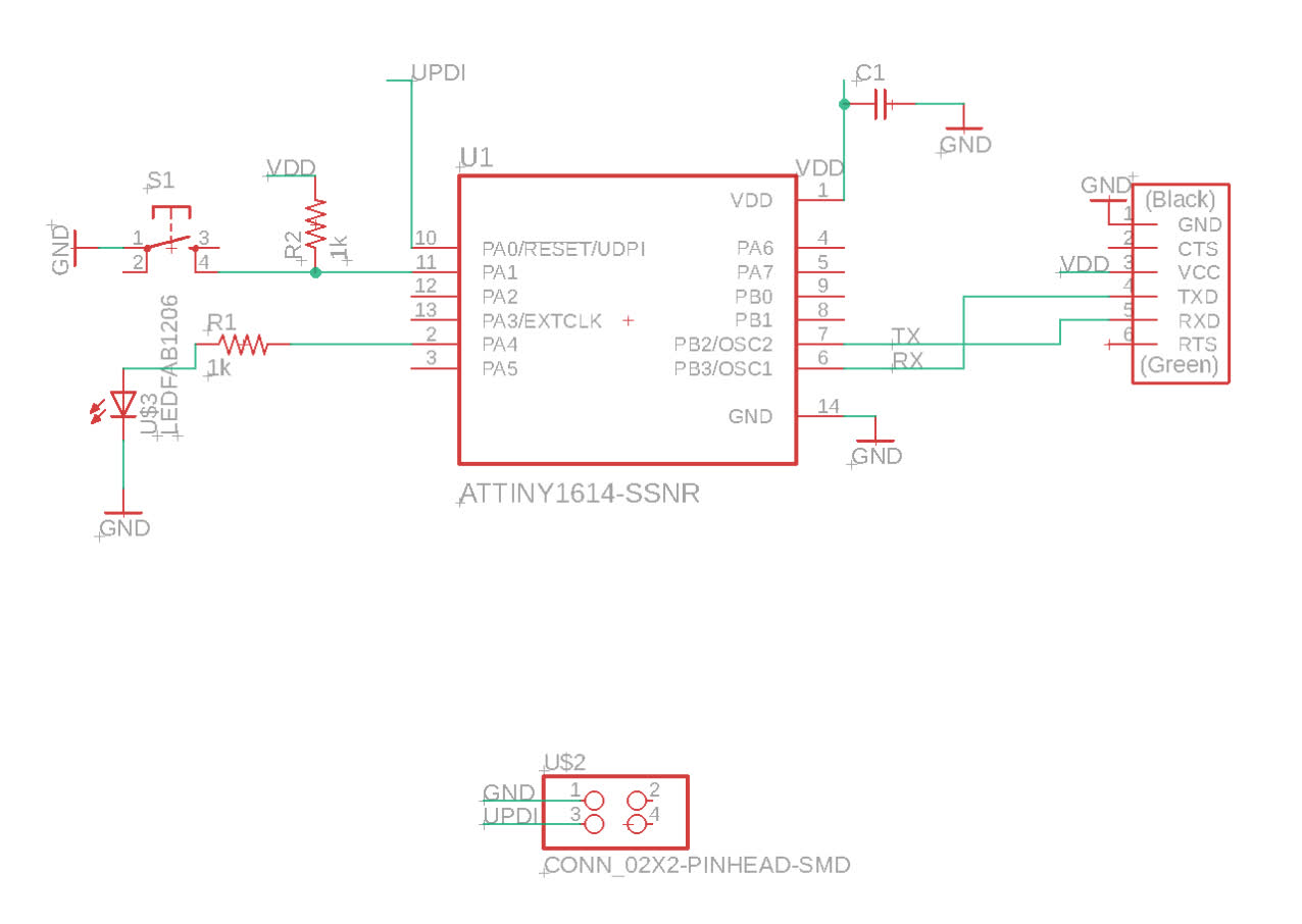
Here is the list of components I had in my schematic:
1. ATTiny1614-SSNR
2. Conn: FTDI-SMD-Header
3. Conn: 2x2 Pinhead SMD
4. R1 and R2: 1k resistors
5. LEDFAB1206
6. C1: C1206FAB
7. S1: SW262CT-ND
Once I was in Eagle, I pulled the above components from the fab (and other) libraries, and started pushing things around and routing connections. I followed Anthony's tutorial in real time for this schematic and generated a board to start running traces.
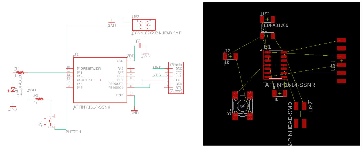
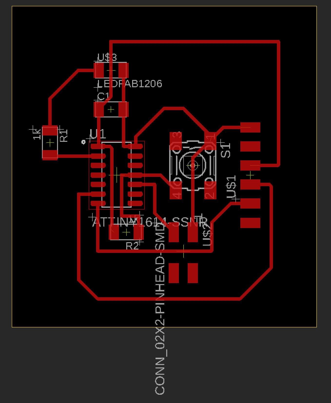
To start drawing my traces, I first set my Design Rules to the 16mil tolerance Anthony recommended in his video. I also set my wire width to 16 to beef them up a bit. I then spent a while trying to route traces based on this schematic, but I was unable to make all my connections work. Someone more practiced might have found a successful way to route the traces in that set up, but I decided to make changes to the schematic instead. The resulting setup allowed me to make all my necessary connections. See the schematic and board below:
Time to export. I turned off all layers but the "top," which held the traces. I exported an png image because I planned to use mods to generate my gcode. The exported the traces png at 1000dpi, which looks good, understanding that when I import it to mods, I should double check my dimensions and resolutions, and will likely need to adjust my file to 2000dpi. The png looks like it should though:
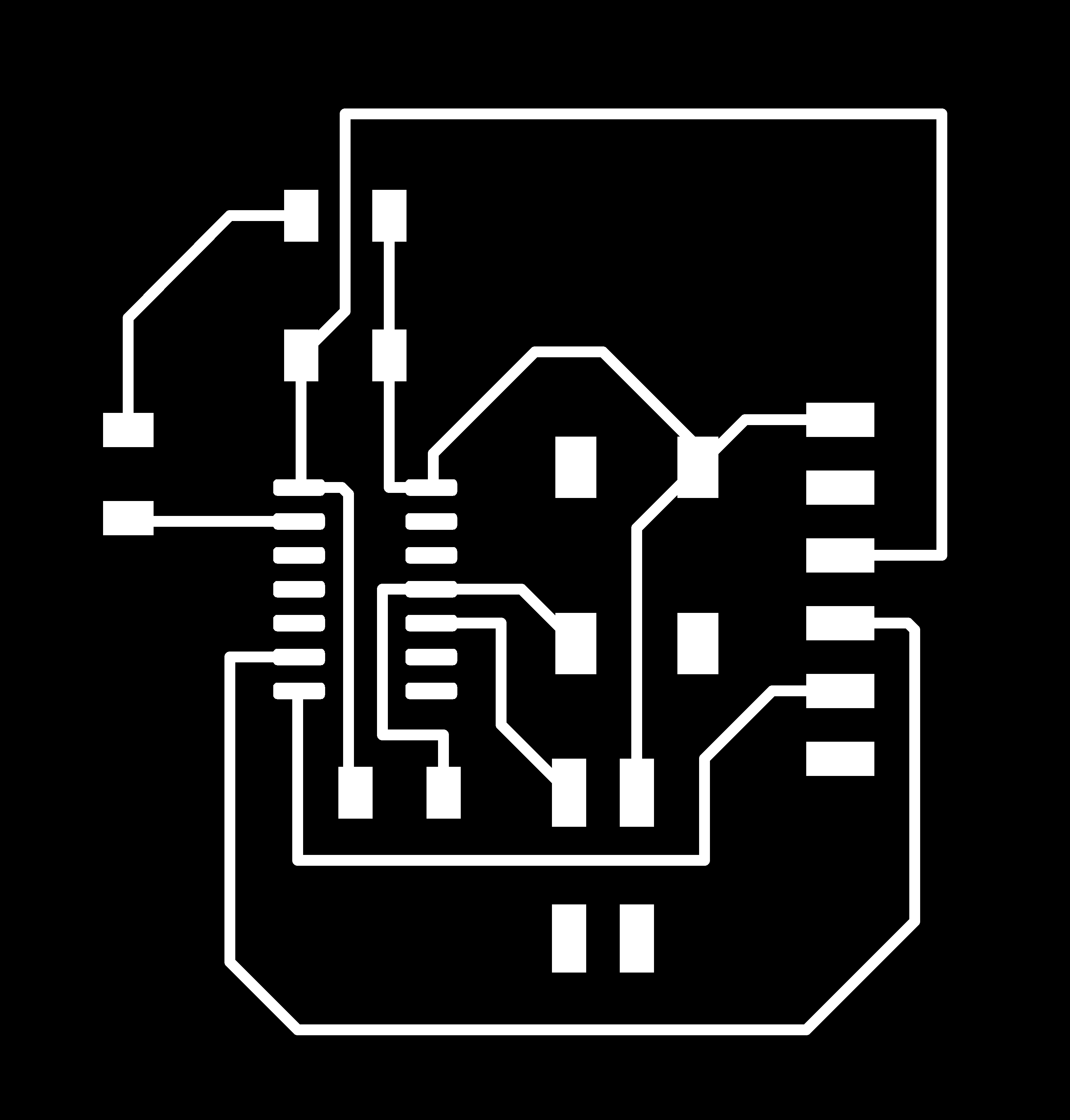
I hit a speedbump at this point, though, because I couldn't figure out how to export the interior file for cutting the border that we see in Neil's helloworld boards. I played around a little, but couldn't figure it out, and in the interest of keeping the process moving forward, I created a border in illustrator, making sure to maintain file dimensions. I did have an issue once I imported it into mods. The 2x adjustment to the dpi no longer worked once I ran the files through Illustrator. I may have saved something wrong. This wasn't a huge problem, though. I was able to manually adjust the dpi on both the traces and interiors in mods to ensure that their dimensions corresponded to each other.

Eagle >> Illustrator >> Mods >> Clank
The architecture section has been sharing successes and failures in all things mods and clank, and through some very frustrating moments and a lot of lost bits, I think we've landed on some pretty hard won knowledge about the best mods settings for our clank to run smoothly. The biggest takeaways: slow down the cut rate, increase the number of passes and up the spindle speed. The below settings worked pretty well, but I think we can still do better:
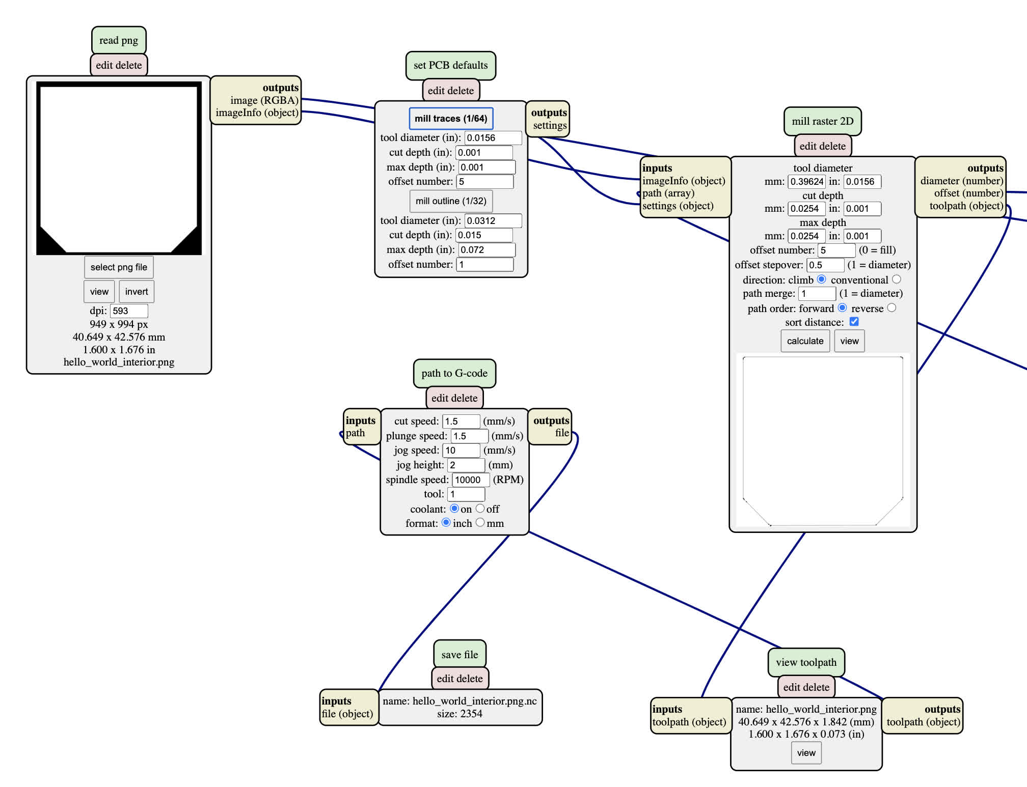
Gcode generated for traces and interiors. Now to wake up Clank again.
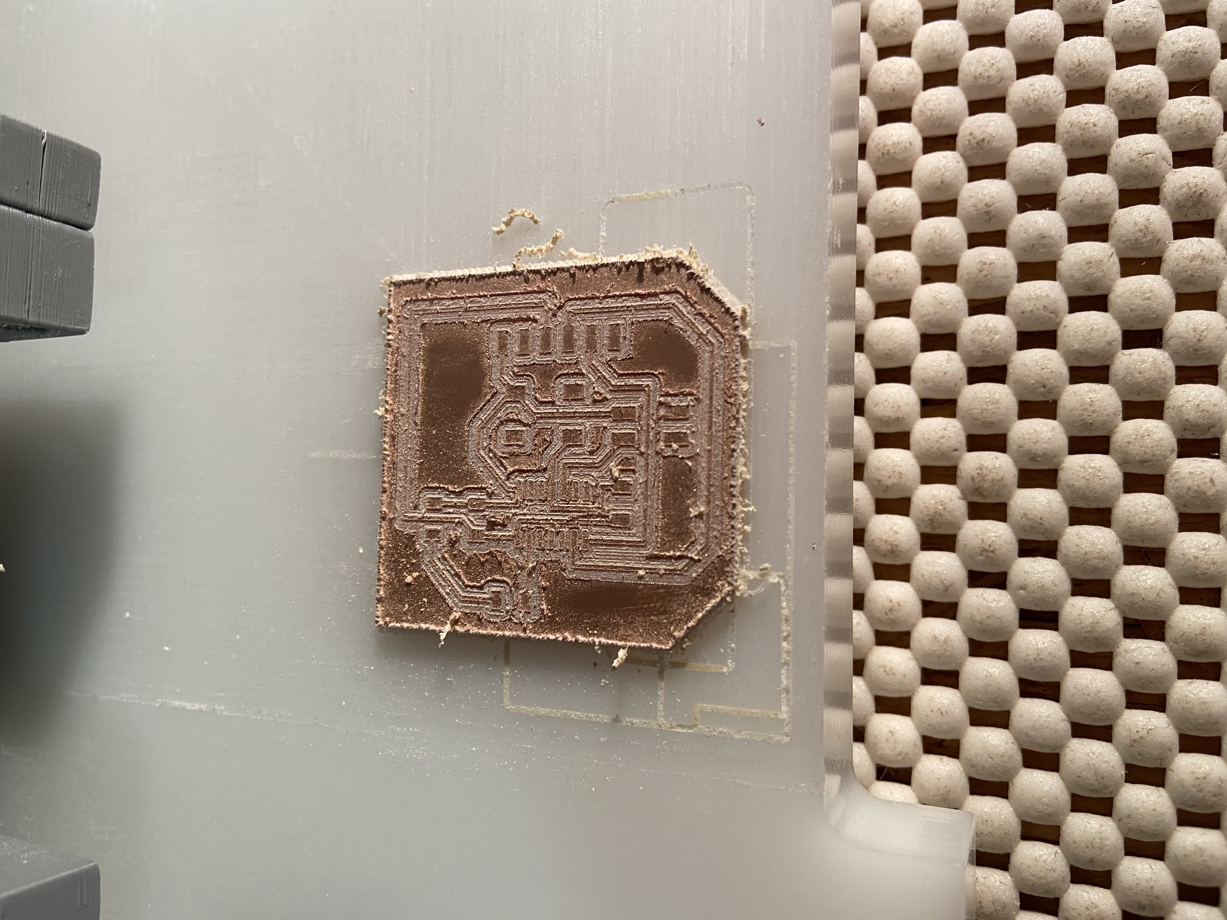
Finally, in my third attempt, I was able to mill a board all the way through. I also increased offsets form 4 to 5 to give myself a little more room. I think I could stand to increase that even more now that I have the updated firmware in the z-motor and running a longer cuttime is won't threaten to melt my machine. But I'll save that for next time. I just did a little manual clean up on this one that took about 5 minutes.
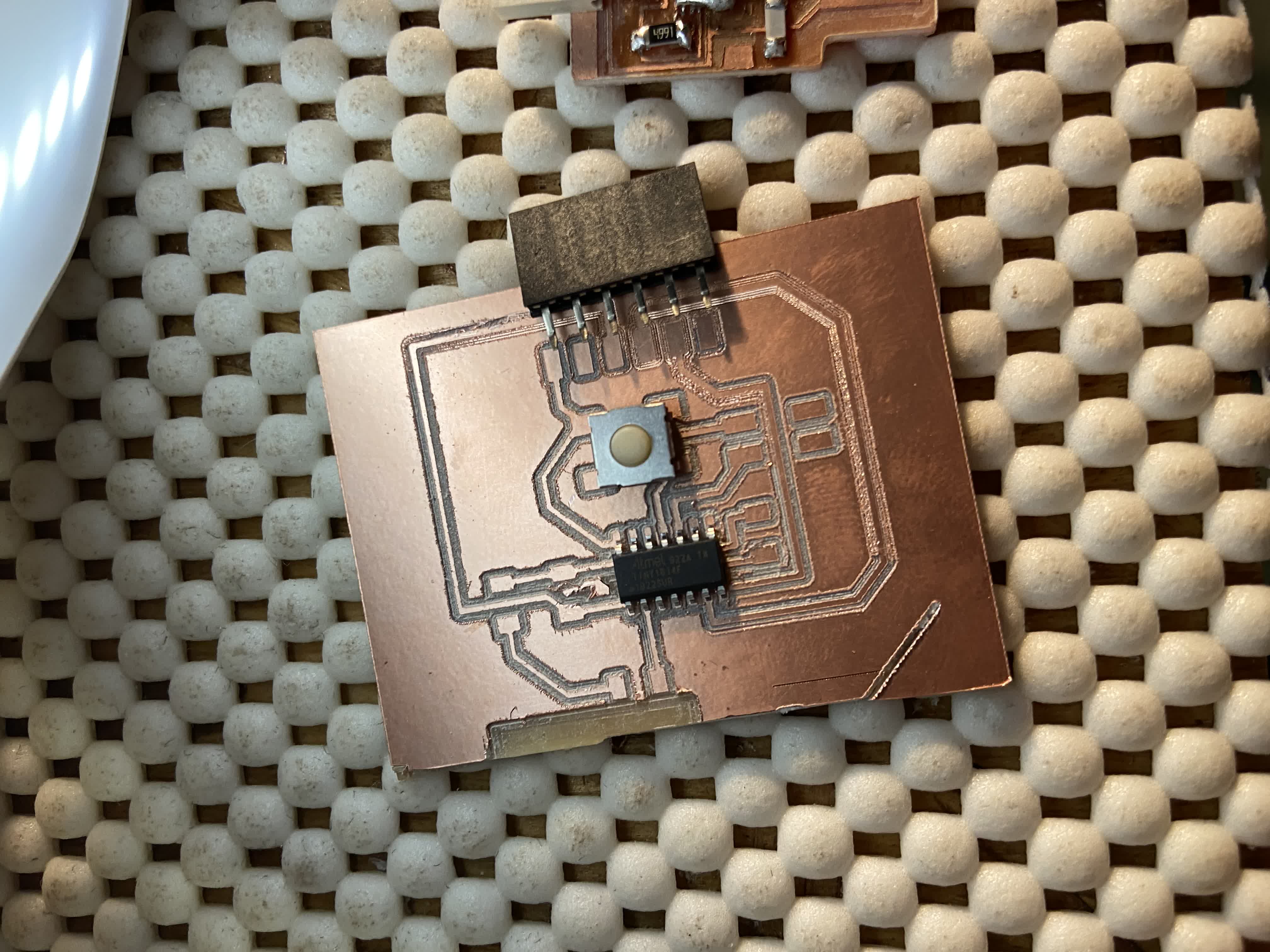
With a board cut, it was time to stuff it. You can see my handiwork below. I really want to get better at this soldering business. I need to get more comfortable with the removal process. I think that will help
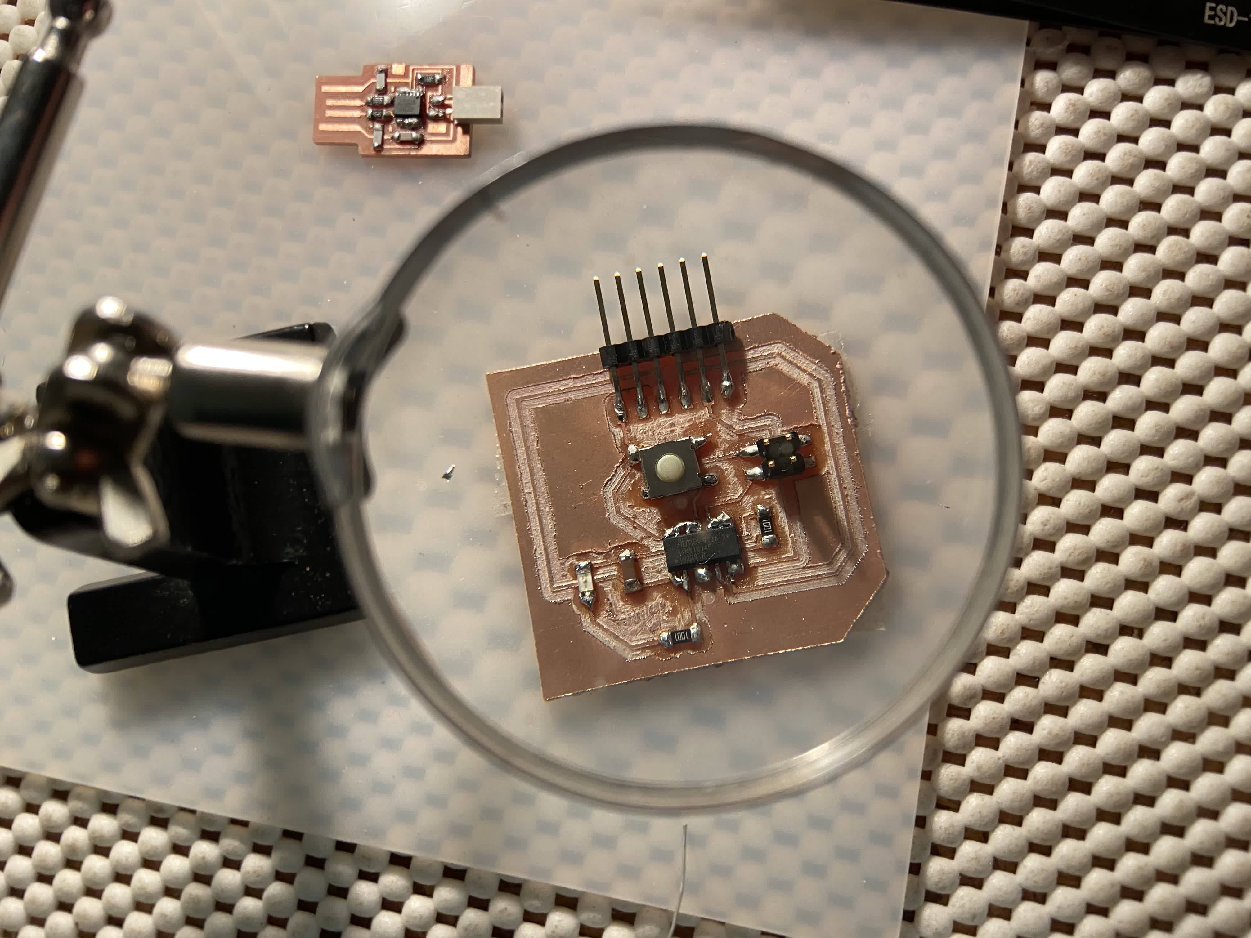
Anyway, the components are on there. I haven't had time to test it yet, but that is next on my agenda. I am now comfortable with generating a board in Eagle and bring that through to Clank and the post-milling process. What I still
need to work on is the actual schematic building phase. I need to become more literate with reading and understanding the data sheets and overall just gain a better grasp of what these boards are doing.
Files: