Week 7: Embedded Programming
Group Assignment: Compare the performance and development workflows for other architectures.
Group assignment pageIndividual Assignment: Program a Microcontroller to do something
Step 1: Read a microcontroller data sheet
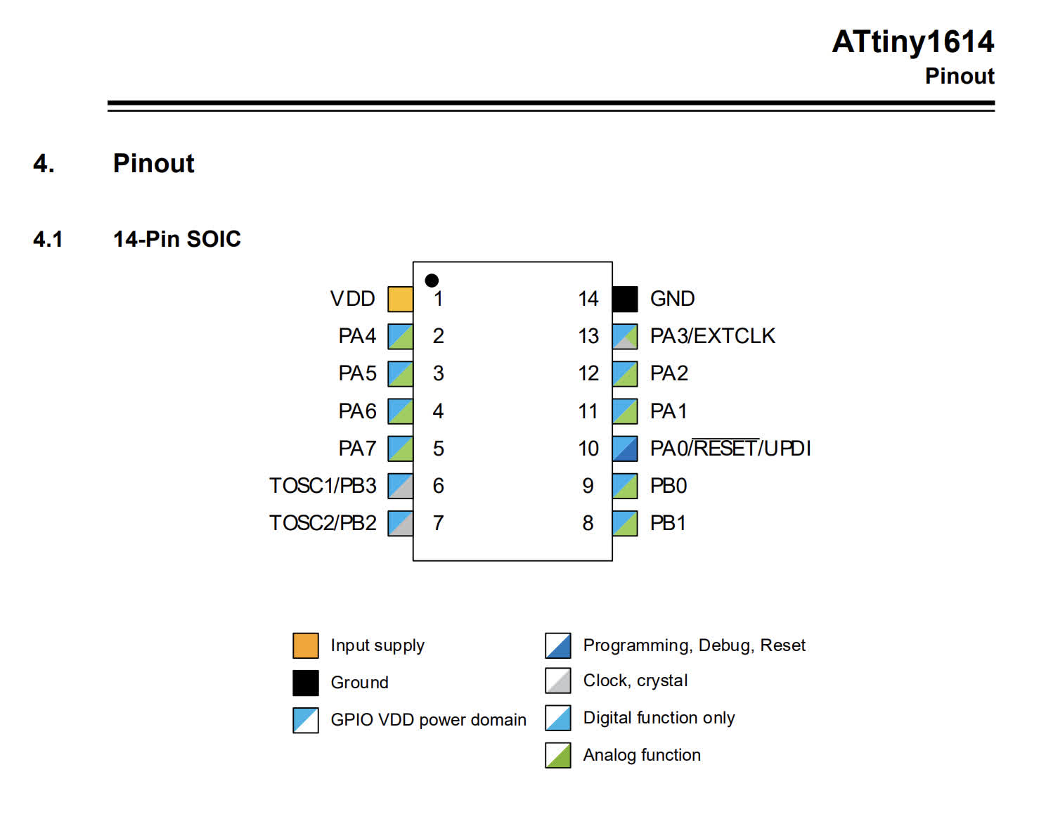
In speaking with the many wise HMAA staff members about which microcontrollers are good for which situations, I decided to continue forward in using the ATtiny1614. I had familiarized myself with the data sheet a bit last week, and it seems capable of doing pretty much all of what I need it to do for my final project -- which mostly involves turning on an LED light and communicating with an external input device, maybe uses wireless. Anyway, I found the pinout (immediately below) to be the most usefully and intuitive tool to follow as I created my schematic.
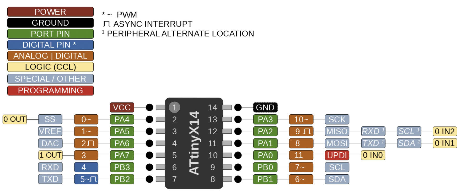
I also really liked the megaTinycore chart that Zach shared, which maps from the ATtiny 1-series devices (including the 1614) to Arduino pin numbers. See below:
Now, with the data sheet read, and sort of understood, it was time to design, mill, and stuff a board!
Step 2: Make a board, solder it, de-solder it, re-solder it
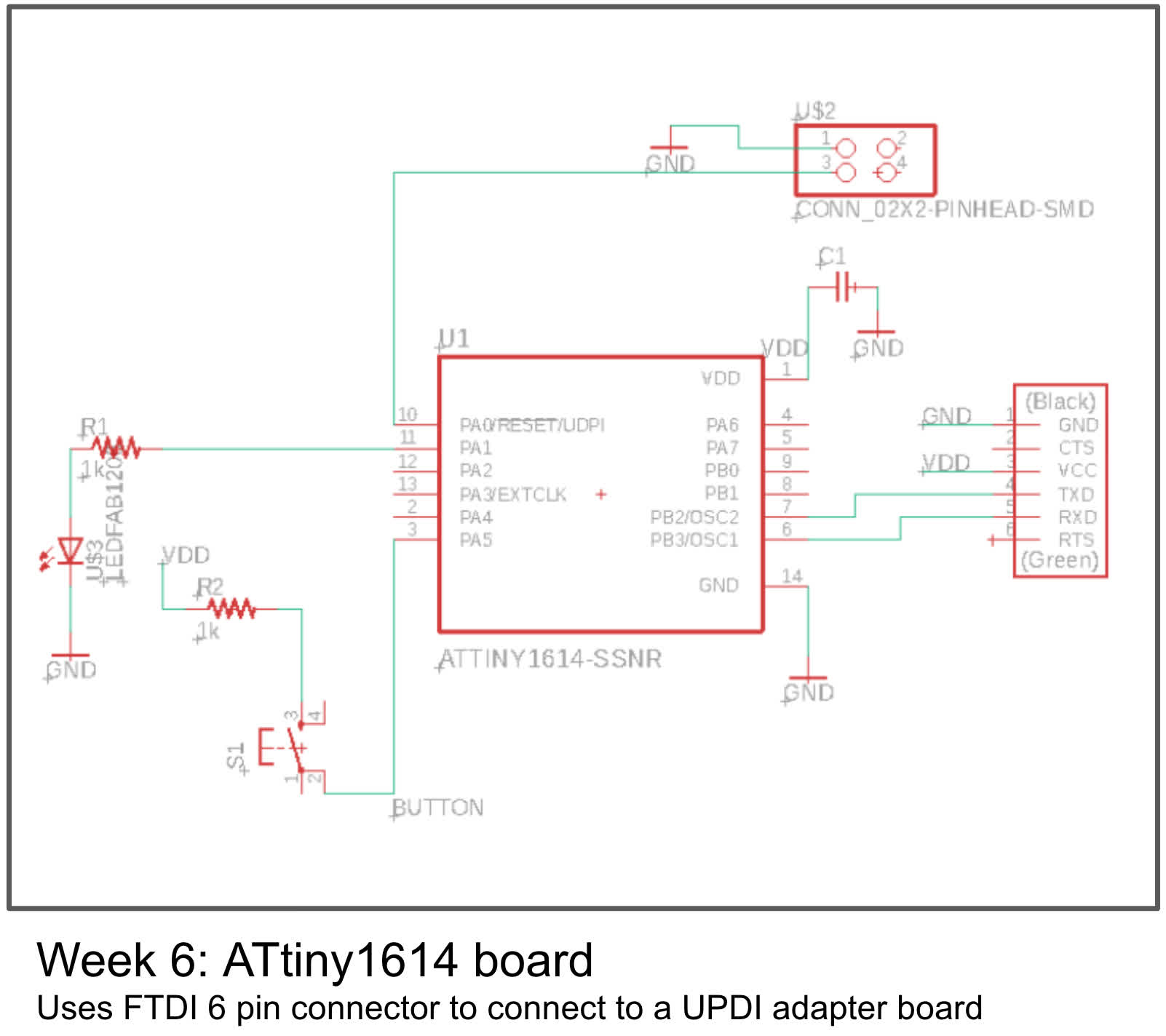
Well, I could have used the ATtiny1614 hello world board I made last week, but in order to program that, I would have needed to mill a separate UPDI adapter board. Definitely doable, but given the time it takes to mill a board with Clank, not to mention its penchant for throwing wrenches in the production process, I decided to follow Zach's advice and eliminate the need for the separate board. Below, you can see the original schematic from the board I created last week:
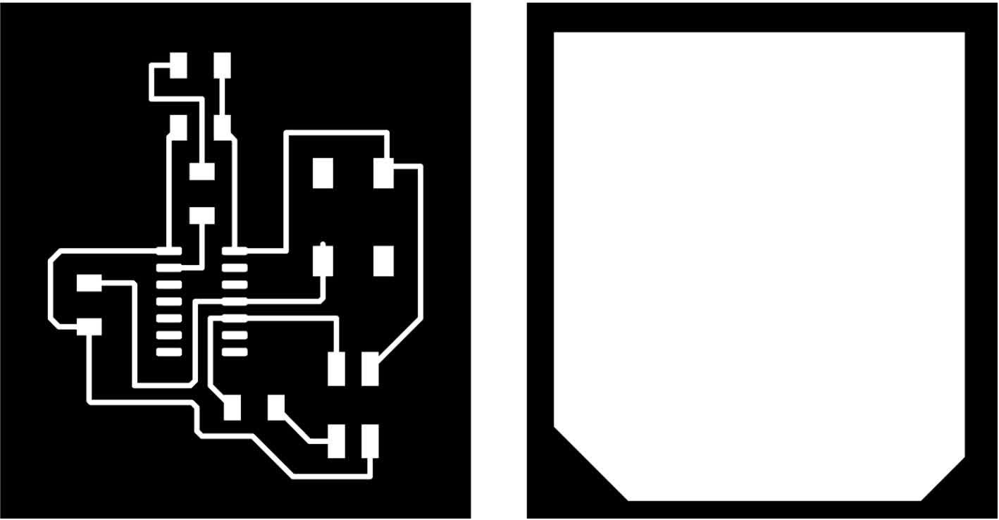
And the adjusted schematic and footprint I made this week based on Zach's tutorial:
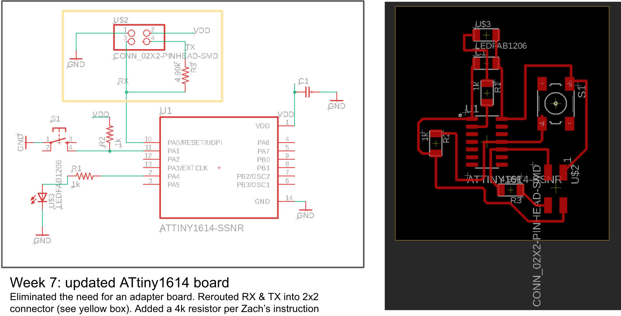
Here is the list of components for the updated design:
1. ATTiny1614-SSNR
2. Conn: 2x2 Pinhead SMD
3. R1 and R2: 1k resistors
4. R4: 4.99k resistor
5. LEDFAB1206
6. C1: C1206FAB
7. S1: SW262CT-ND
With the layout complete, I exported the PNG of the traces from Eagle, and created a cutout for the interior file in Illustrator. I still haven't figured out how to do this directly in Eagle. From there, it's just a matter of uploading into mods, checking the file dimensions are accurate, calculating and exporting the g-code to the Clank interface. (Side note: Neil has updated the setup for Clank, and I find the mods defaults for 2D PCB milling mostly work. I just slow down the cutting speed from 2.5mm/s to 2mm/s)
After successfully milling the board, I stuffed it.
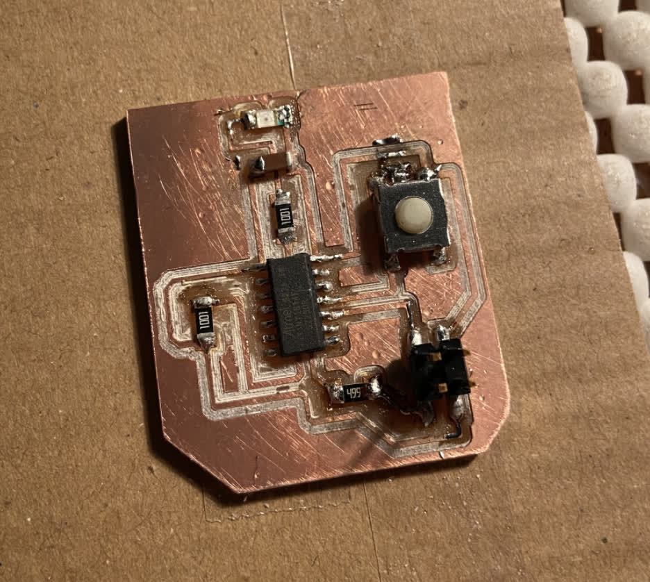
I tested the board to make sure soldered joints were working, and while it seemed fine, I reached out to get some more expert opinions. I'm glad I did because the three TAs that responded all told me the schematic looked good, but the ATtiny1614 chip was backwards. It needed to be rotated 180 degrees. From Zach: "Manufacturing looks physically sound, but I believe the ATtiny1614 is on backwards. The "1" pin is the one with the little white circle next to it; if "ATMEL" is upright, it's in the lower left. Right now you have VCC and GND connected to pins 7 and 8." So I did a little de-soldering using my heat gun at 350C. This was too hot, and I scorched my board a bit. See the fix and the evidence of the overheated board below:
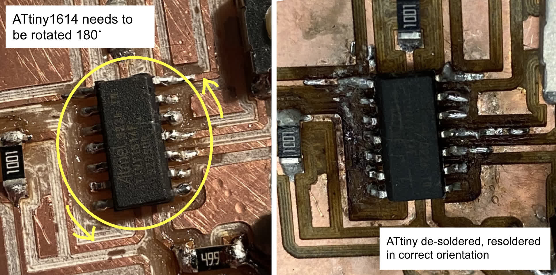
So the board isn't as pretty as it was, but I tested the connections with my multimeter, and things seemed to be in order. Time to get to the actual programming
Step 3: Programming the board to do something
By far the most most difficult part of this week was just figuring out the workflow between stages of the process. Making sure to have the right things installed took a chunk of time, and then figuring out how move code from the Arduino IDE was a bear in and of itself. Zach's programming tutorial for the ATtiny412, ATtiny1614, and ATtiny3216 is really helpful, but even though he walks through the process step by step, I kept running into errors because my path to hex file was not working when I tried to enter it in the terminal. So I went to meet Anthony in person, and he helped me trouble shoot. We finally figured out the issue by navigating manually into the folder where I saved my Arduino file.
Ok. Now for the actual programming and testing of the ATtiny1614 board. First, I used a simple Blink example on Arduino:
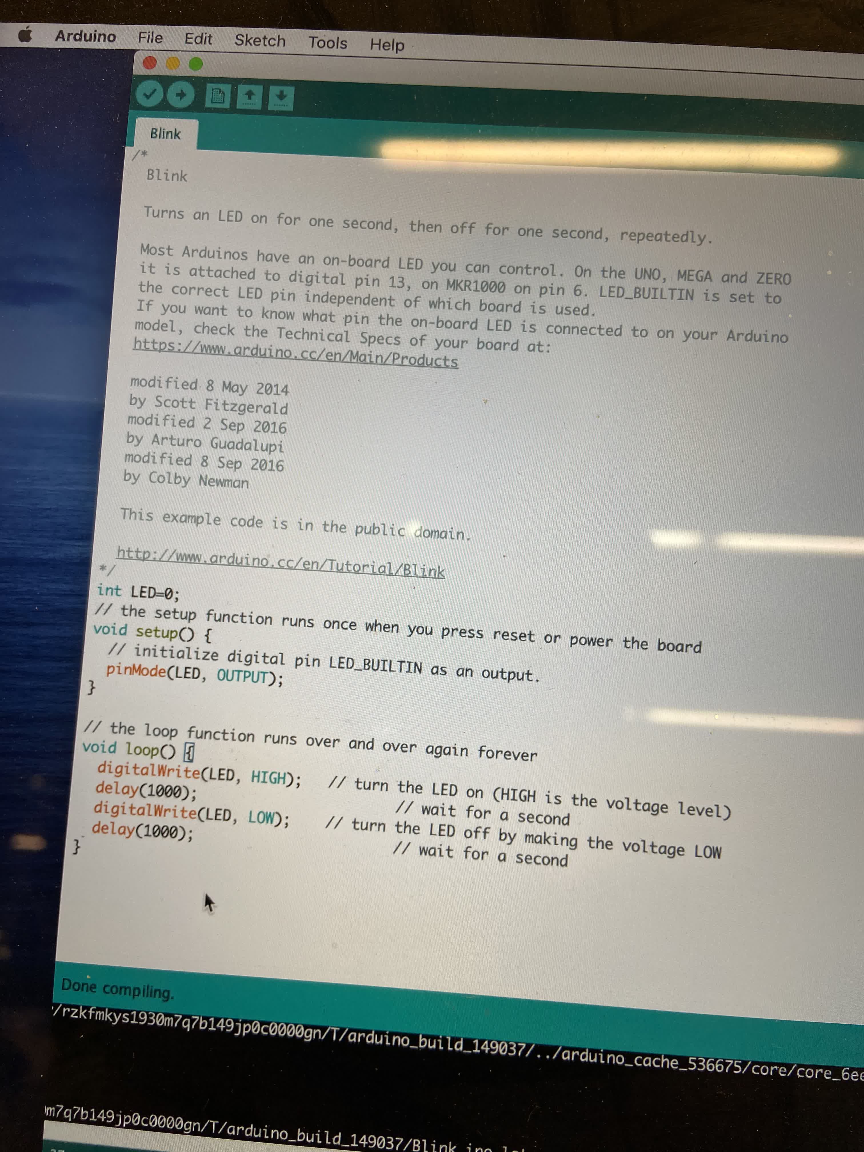
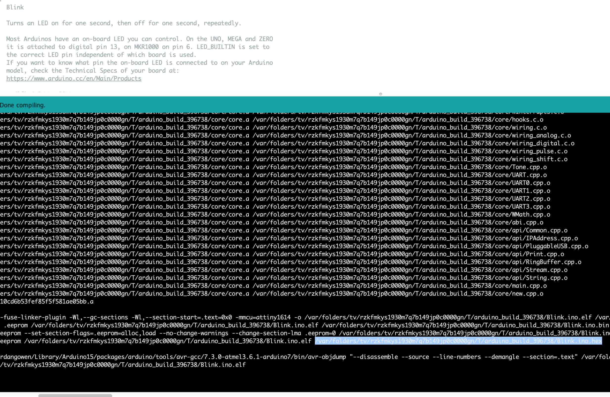
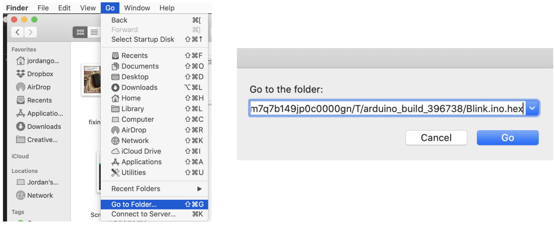
After clicking "verify," Arduino will generate and export a hex file. I need to figure out a more efficient way of finding the hex file, but for now I was able to comb through the black box below the code, find the .hex ending, copy the path and use "go to" in Finder to find the hex file. Then I copied the .hex file into the same file as the where the .ino file ended up. In this case I had Blink.ino on my Desktop
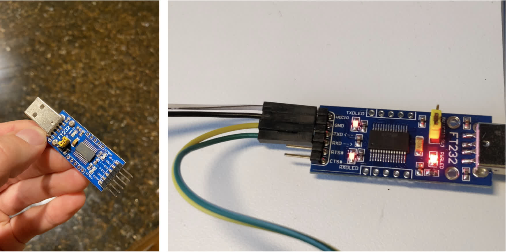
To connect my board to the computer, I used the serial adapter from our kit.
Once the adapter is hooked up, I'm ready to push the code through pyupdi.py. See the terminal command line below:
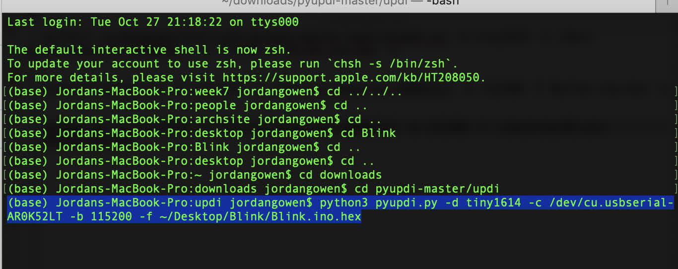
And the LED light blinks!
But the button wasn't doing anything because I hadn't told it to do anything. So I wrote some code in Arduino to tell it do something.
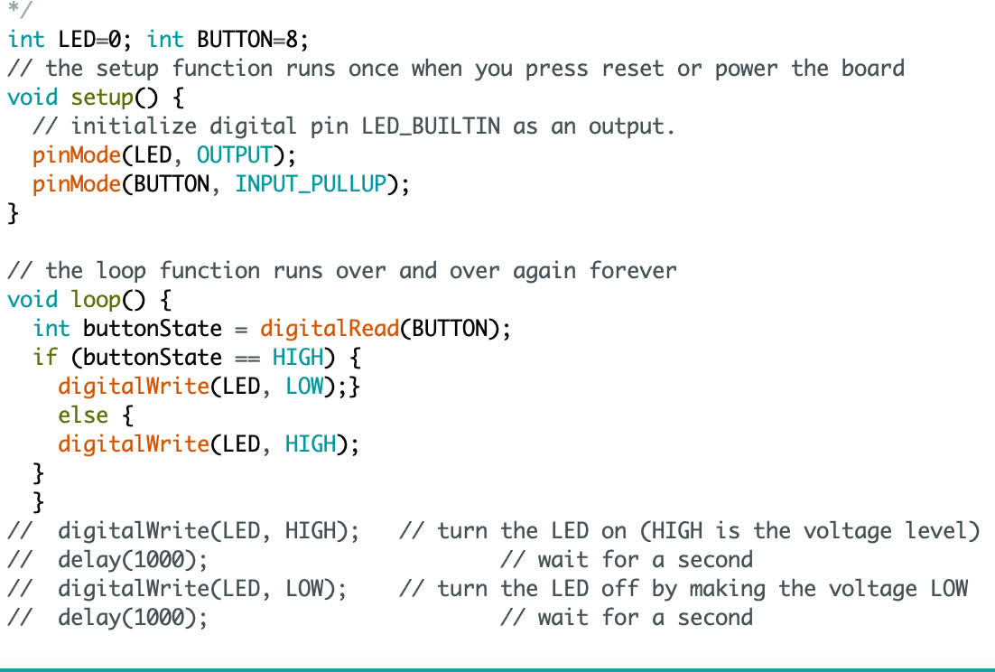
And it worked!