Week 8: Input Devices
Group Assignment: Probe and input device's analog levels and digital signals.
Group assignment pageIndividual Assignment: Measure Something: Add a sensor to a microcontroller board that you have designed and read it.
Step 1: Pick a Sensor (or sensors)
Having already determined that I'd like my final project, my lamp, to be sensitive and responsive to ambient light, I decided to focus on using a PHOTOTRANSISTOR as my input device this week. If time permits, I'll also play around with CAPACITIVE SENSING as an alternative to a more standard on/off switch. I have a feeling that's going to be an ambitious scope for this week given the time I invested in programming my simple button and LED last week.
Still, I think that these two input devices work well in concert together, so I'd like to start pushing towards that end in this week's assignment. Side Note: I found some great examples of past projects that have incorporated one or both of these functions in their project. See Eva's Fablux Lamp from FabAcademy Barcelona, Marjo's LED Lamp from FabAcademy Oulu, Finland, and Alex's CastLight project from HMAA 2019.
Step 2: design a board with a phototransistor
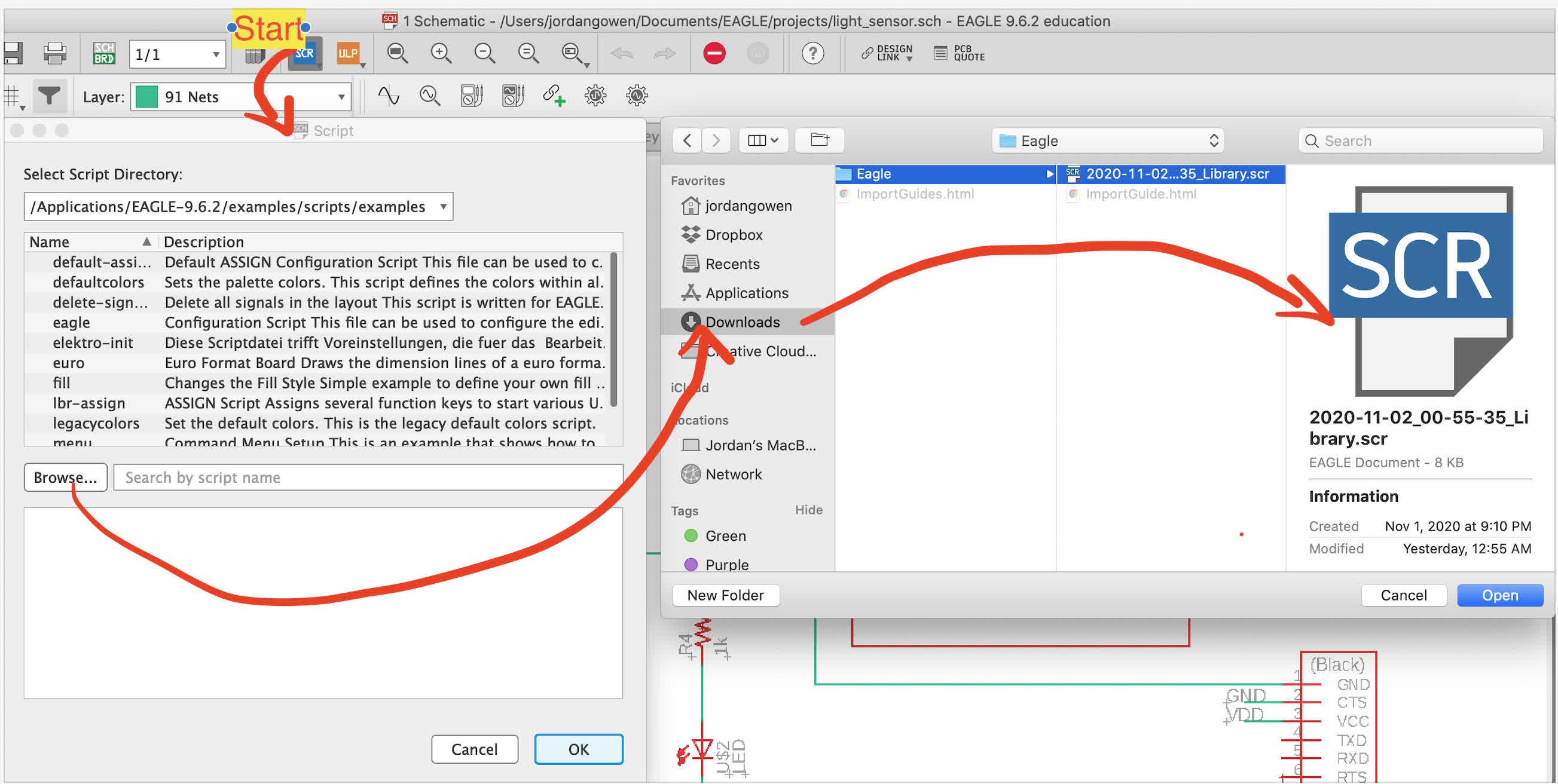
Using the ATtiny1614 felt like overkill for a single phototransistor, so I downsized to a ATtiny412 for this week. This was probably a mistake because I spent the good part of a morning just trying to find and add a 412 to my Eagle library options. I was able to download a footprint from this link, but the download was not a .lbr file, so it required I run a script instead of simply adding through the library manager. Cody was helpful in troubleshooting this one. Once I had the step-by-step from her, it was a pretty easy process, and I could add the ATtiny412 to my schematic
Before creating my schematic, I spent some time reviewing the 412 data sheet to understand the pins. I basically used my ATtiny1614 board from last week as a template, just adjusting the component placement based on the pin layout and replacing the tactile button with the phototransistor. See the resulting schematic below:
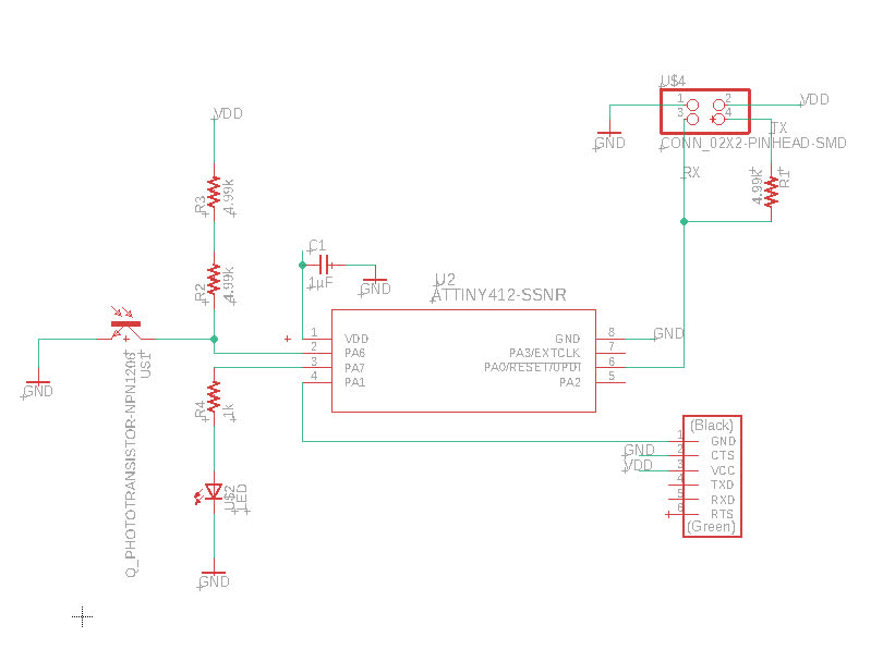
Here is the list of components for the design:
1. ATTiny412-SSNR
2. Conn: 2x2 Pinhead SMD
3. R1: 4.99k resistor
4. R3: 10k resistor
5. R4: 1k resistor
6. LEDFAB1206
7. C1: 1µF capacitor
8. Phototransistor: Visible Light
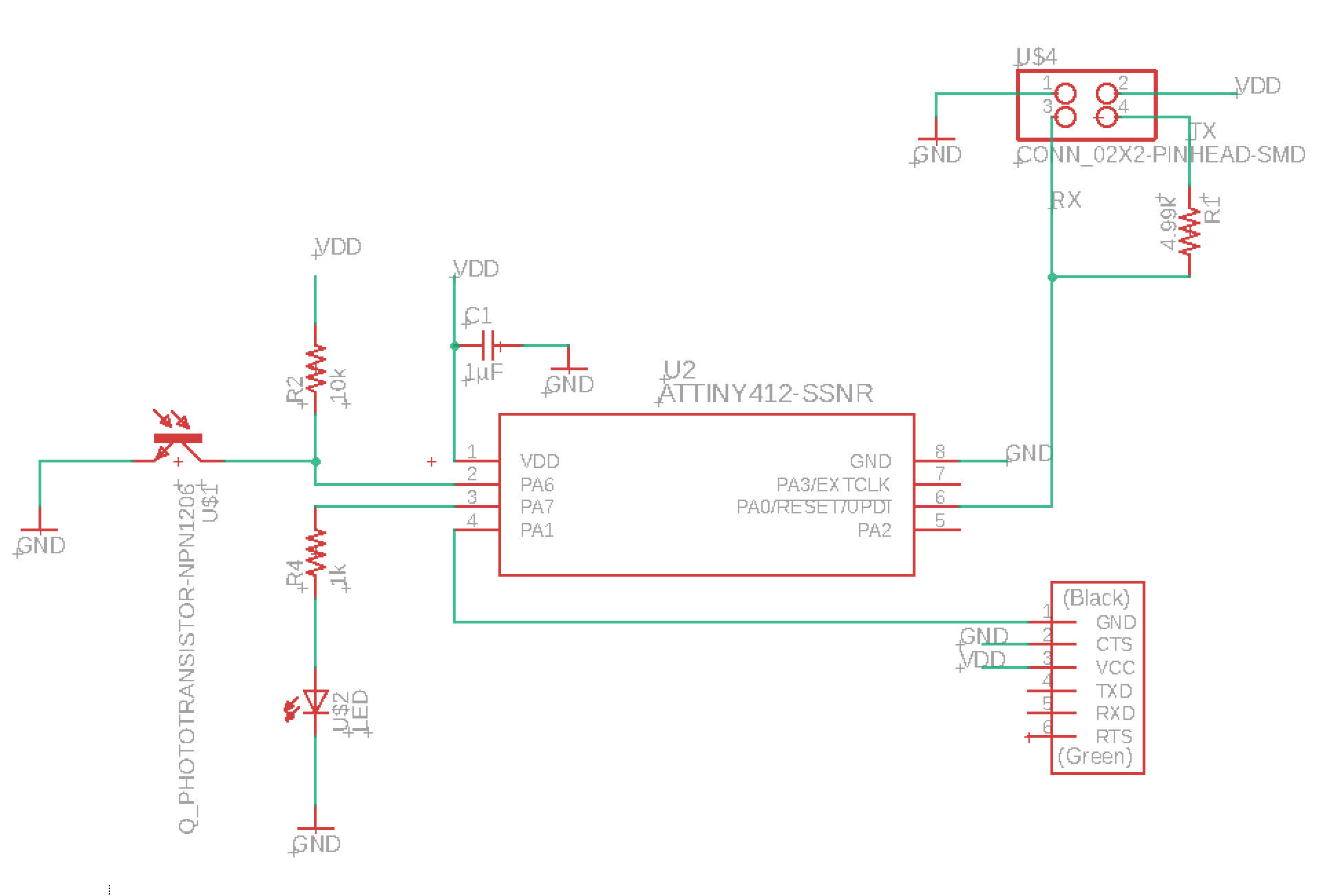
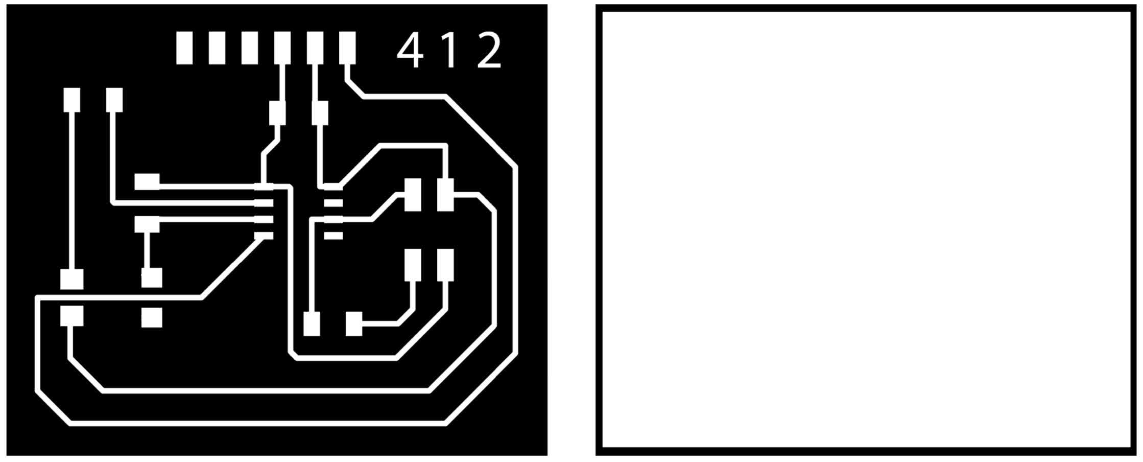
I sent the schematic to Anthony for review before I spent time routing, cutting and stuffing the board. He told me it looked pretty good, but note that I had forgotten to name the VDD line and that I should just swap my two 4.99k resistors for a single 10k (I had place the 2 4.99k because I didn't have a 10k in my kit). I made the adjustments, which you can see below along with the layout for wired traces:
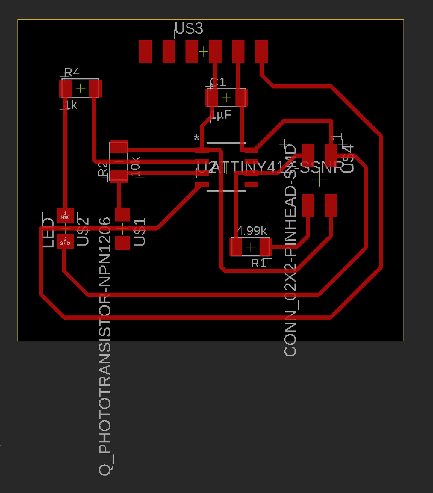
I then exported a png for the traces and created a cutout path in illustrator.
Step 3: mill and stuff the board
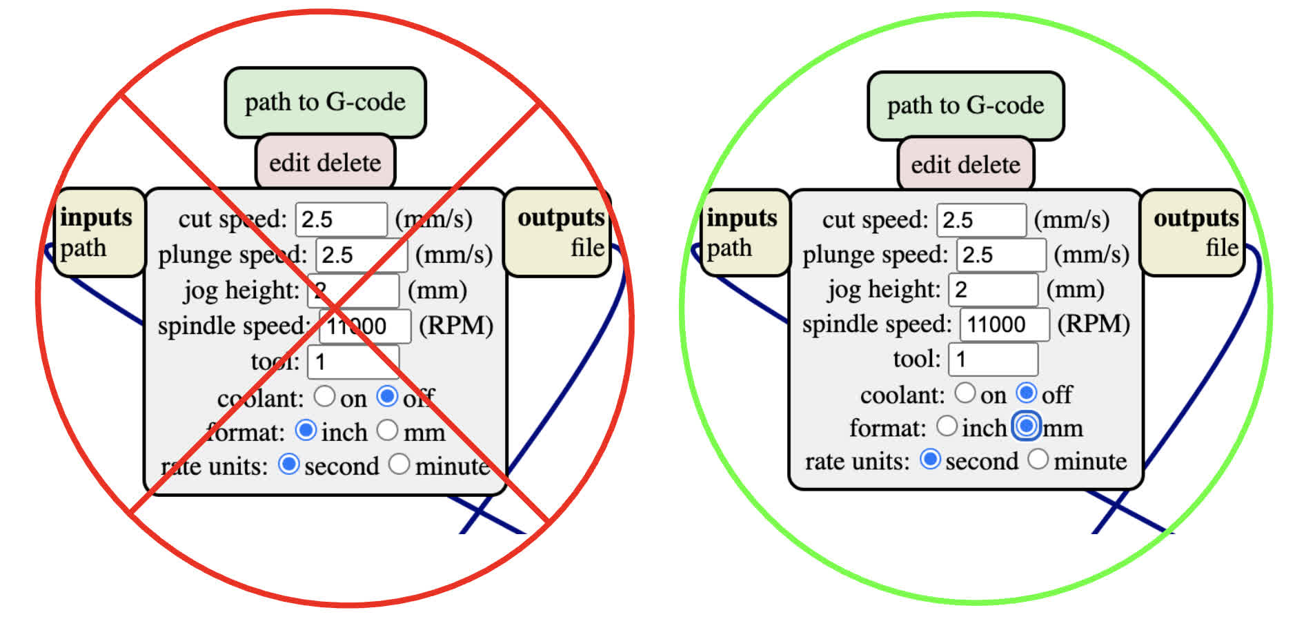
A quick note on the mods setup. I missed Neil's note in the issue tracker, which could have ended much worse than it did. Apparently there is some error with the feedrate being generated. For now, I make sure to select mm/s in path to g-code module. The super fast cut didn't destroy my board entirely, but it was definitely a rough cut, sitting at the upper limit of a feedrate the Clank can handle.
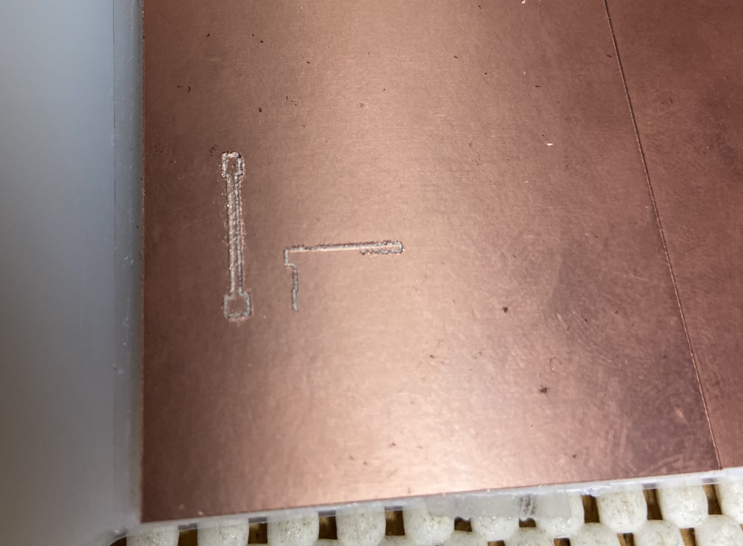
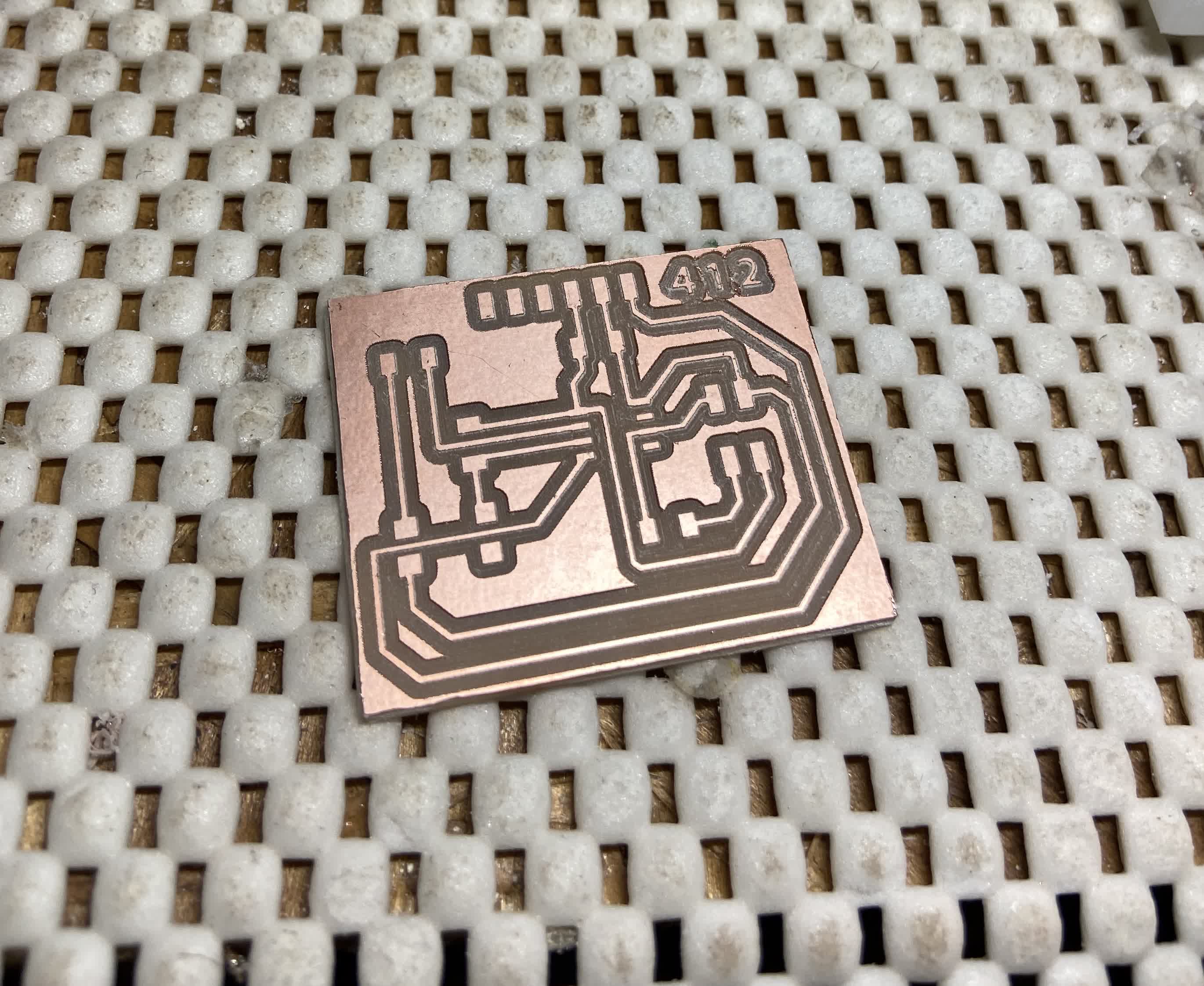
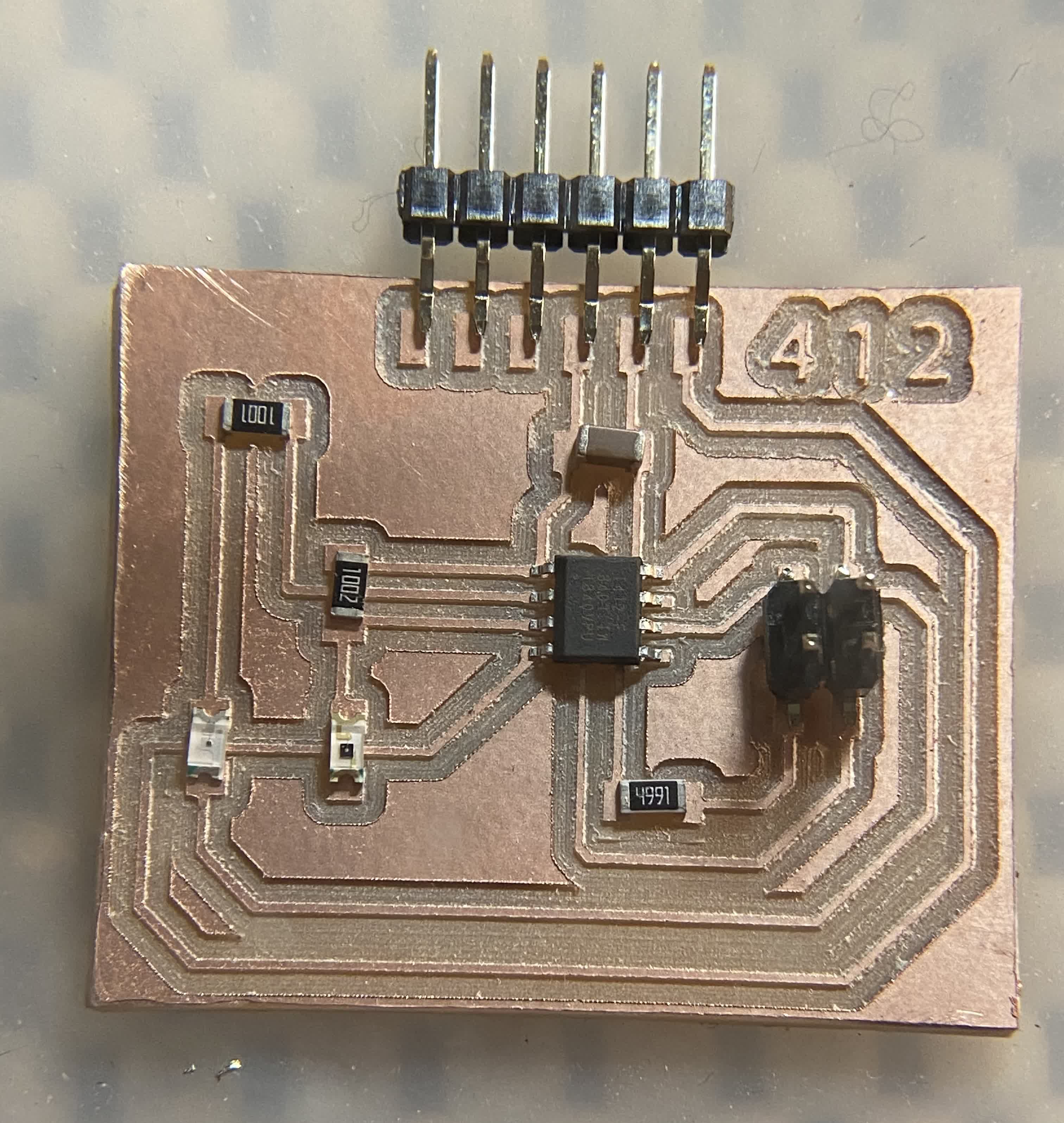
The adjusted settings worked pretty well. The traces cut out at a standard I've come to expect from Clank, and the cutout was rough and stopped part way through because my computer fell asleep. But I was able to salvage that and cut through the remaining material with a knife. The result is a decent milled board.
Testing out the fit and orientation of the components. Seemed right, but I think accidentally soldered the phototransistor on the wrong way.
Before trying my hand at the actual measuring, I wanted to test the board. So I adjusted last week's Arduino Blink code for the 412, and made sure my LED would actually respond. It did.
Now to do the actual assignment and measure something.
Step 4: Debugging and Measuring something
So I tried a little bit of coding on my own, but I wasn't able to change anything on my board. It kept blinking per my original programming. So I went and got some help from Anthony
int LED=0; int PT=1; int Lightlevel=0;
// the setup function runs once when you press reset or power the board
void setup() {
// initialize digital pin LED_BUILTIN as an output.
pinMode(LED, OUTPUT); pinMode(PT, INPUT);
Serial.begin(115200);
Serial.swap(1);
}
// the loop function runs over and over again forever
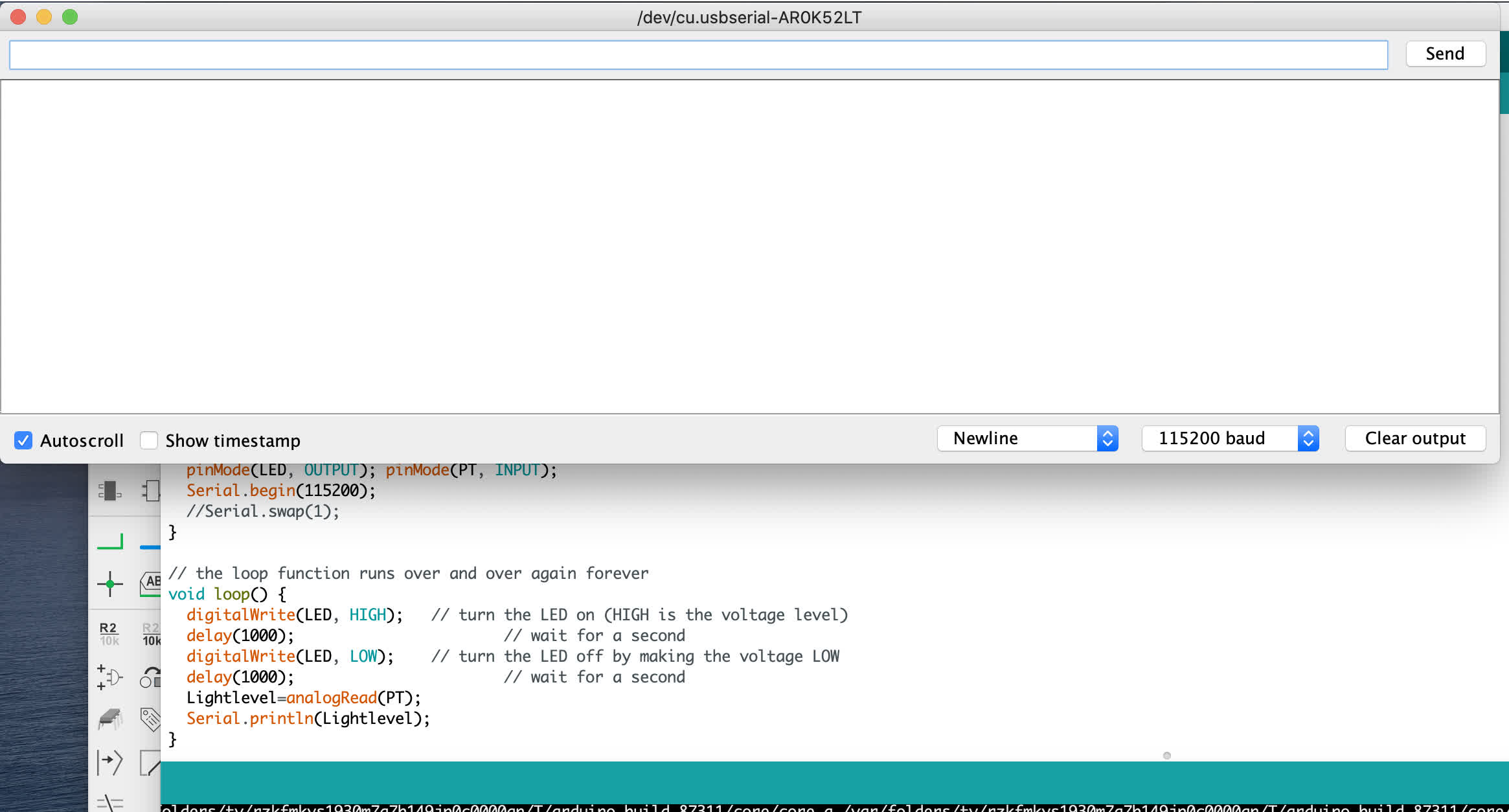
void loop() {
Serial.println ("test");
digitalWrite(LED, HIGH); // turn the LED on (HIGH is the voltage level)
delay(1000); // wait for a second
digitalWrite(LED, LOW); // turn the LED off by making the voltage LOW
delay(1000); // wait for a second
Lightlevel=analogRead(PT);
Serial.println(Lightlevel);
}
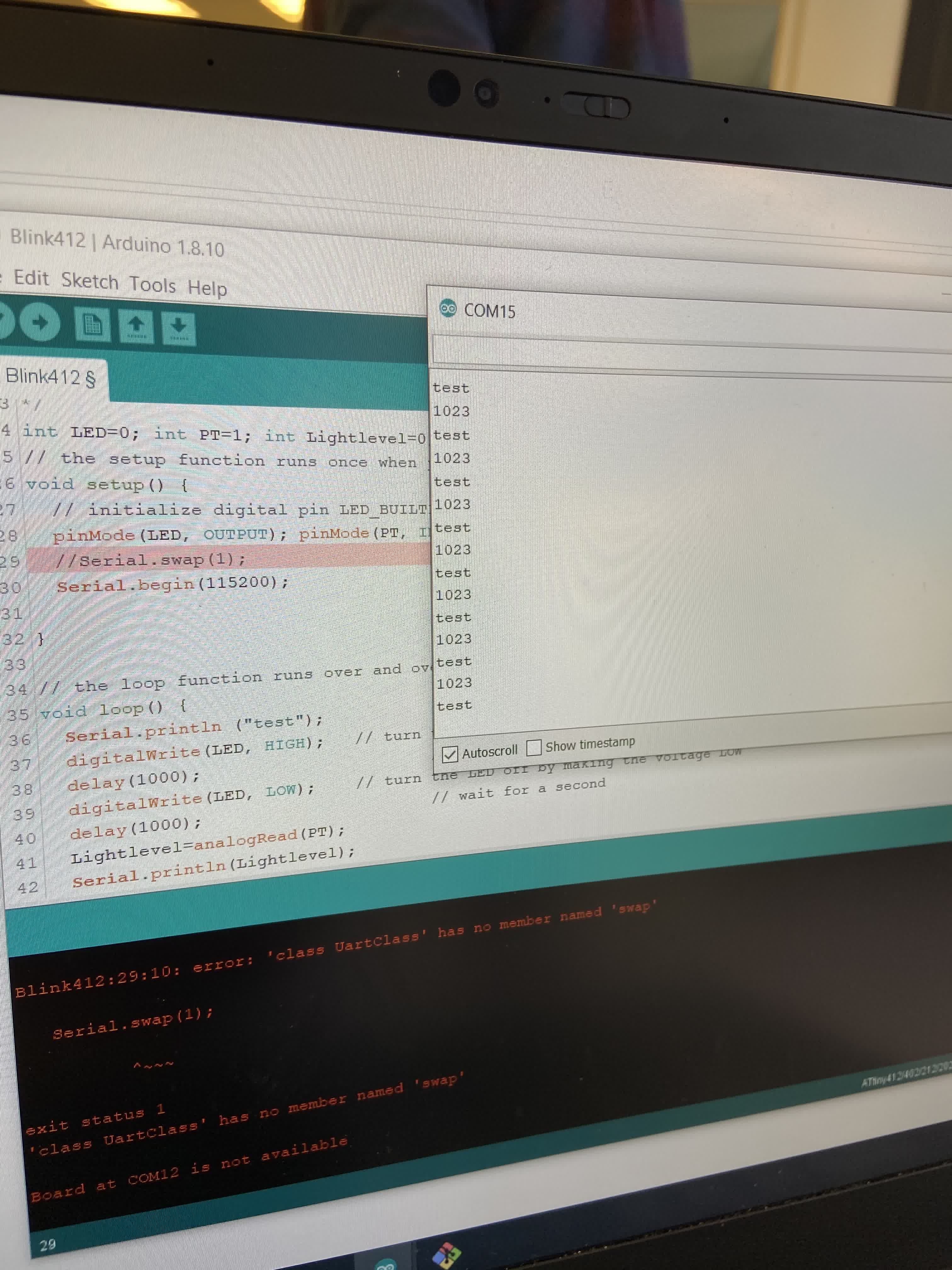
The first time I running the code through serial, I got this error in Terminal:
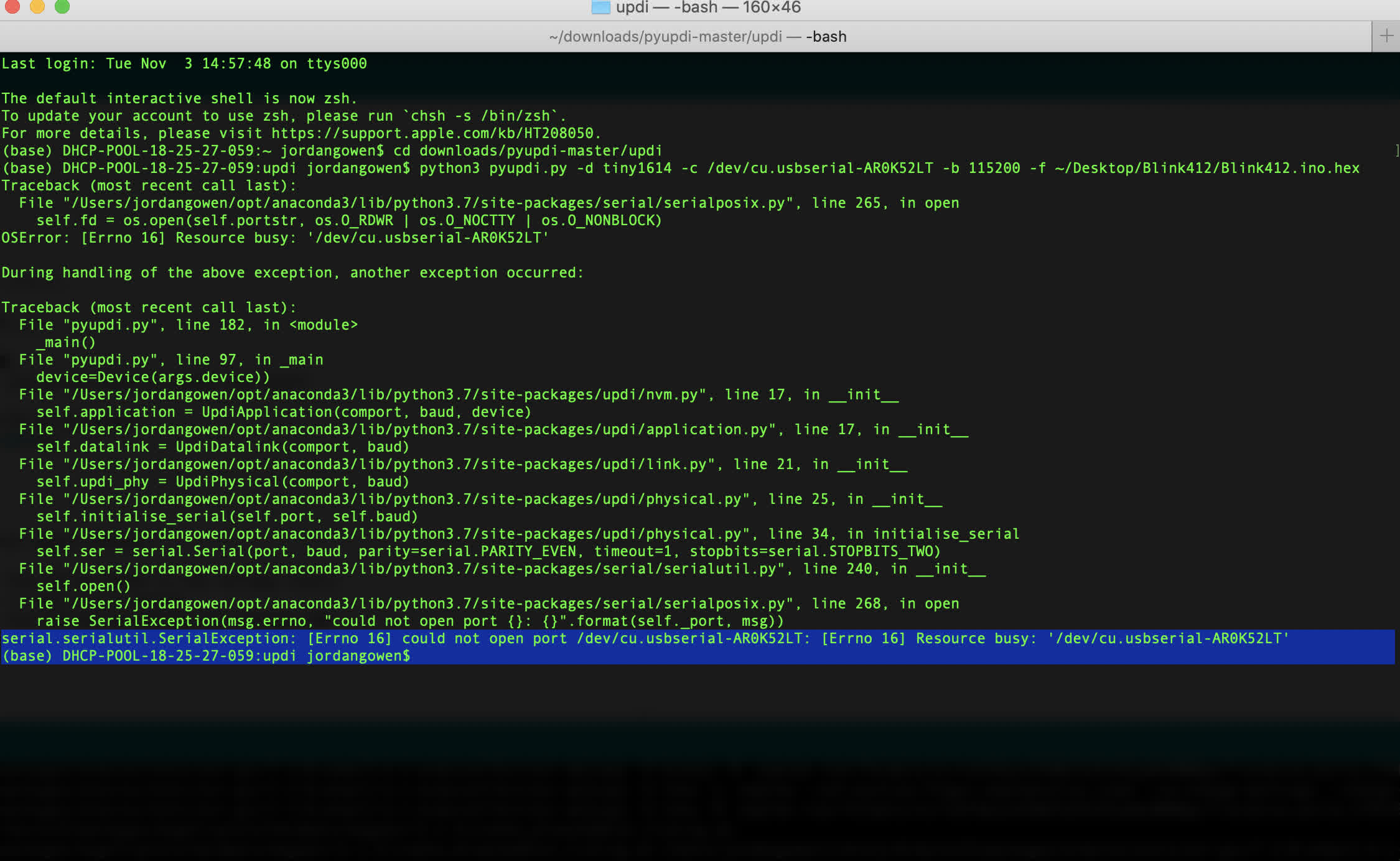
I took the error back to Anthony, and we reviewed the board again just to be sure everything was connected right. Turns out there was a pretty big error. Somehow, while the schematic was correct, the board is itself does not accurately reflect the schematic. The phototransistor is not connected to ground.
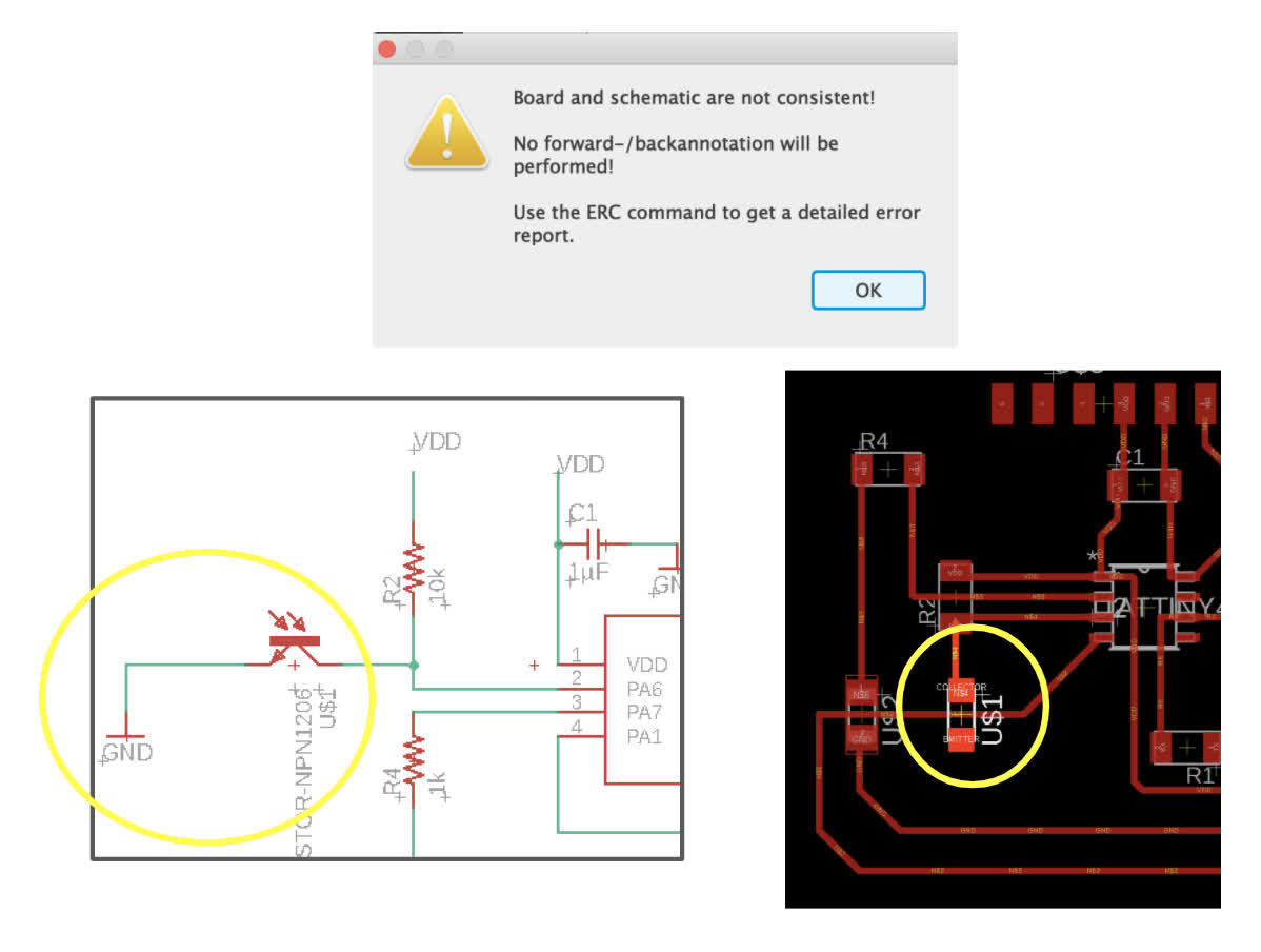
Connecting the phototransistor to ground was an easy fix. Just the matter of soldering a small wire from the transistor to the LED next to it. I hoped the fix would be that simple. But no. Same lack of response.
I'm really happy I did this with Anthony nearby, and it was also helpful that Evan had encountered a similar issue while trying to reprogram an ATtiny412 board. He had been able to circumvent the issue by exporting the .ino file from my Mac to his PC. He then generated a .hex file in his Arduino (an earlier verion than mine. He was running 1.8.10 and I am running 1.8.13), ran the command and got a successful response.
Covering and uncovering the transistor to generate a different value in the serial monitor/plotter
Running the serial plotter to show a graphical reading.
So, what is going on? Why can't I reprogram the ATtiny412 from my own computer? Anthony thinks there is something about the version of Arduino I am running. It's not in py.updi. But that is above my ability to trouble shoot. Because I was able to program and reprogram the ATtiny1614 last week, I am going to make another board using the 1614 and see if I encounter the same problem. If I do, I may run Linux on my Mac or rent a PC from MIT to exclusively run the 1.8.10 version of Arduino.
Files: