[05 In-Circuit Programmer]
Setting up Clank
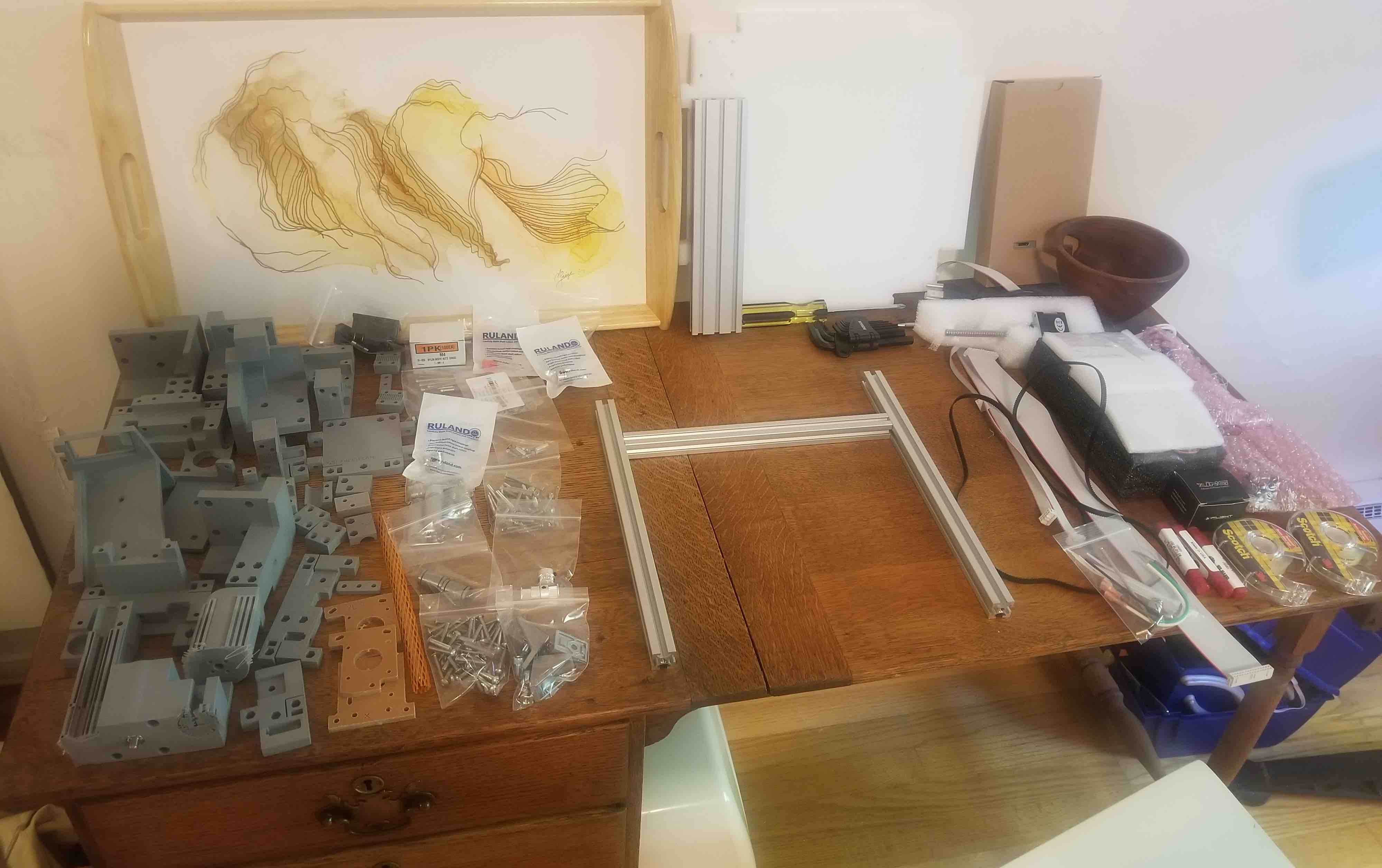
So let me be clear, the title of this week is a little deceptive. The majority of my time this week was spent setting up Clank. Let me introduce you. Clank is an at-home circuit mill that Jake, our fantastic TA, so kindly put together for us. It's basically a giant lego set that we were given videos on how to put it together. It took me nearly 7 hours to get this beauty built. Here are all the parts ready to be assembled hanging out on my sewing desk:
The videos were great walk-throughs. Only recommendation I would have is for someone to watch a step right to the end, then go back and do that step. Since Jake was figuring this out too, sometimes he'd find he had to adjust an instruction slightly and if I'd paused to finish it before watching the full thing I'd have to go back, take that step apart and re-do it.
Trying out Clank
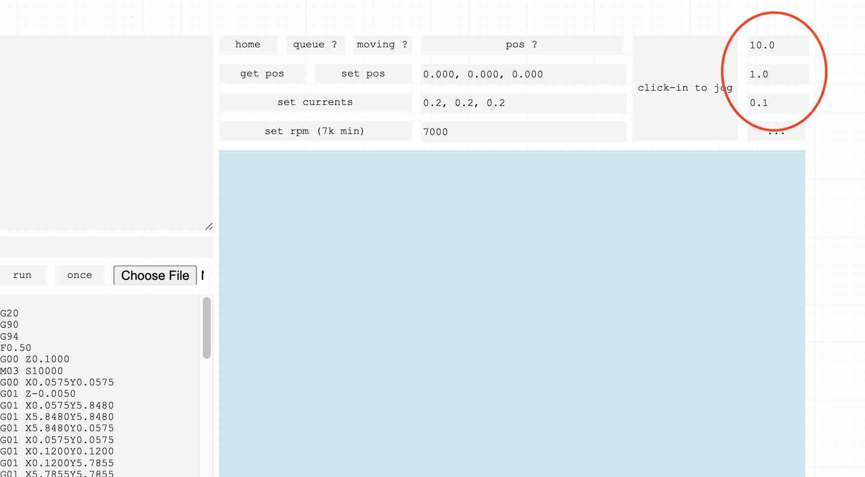
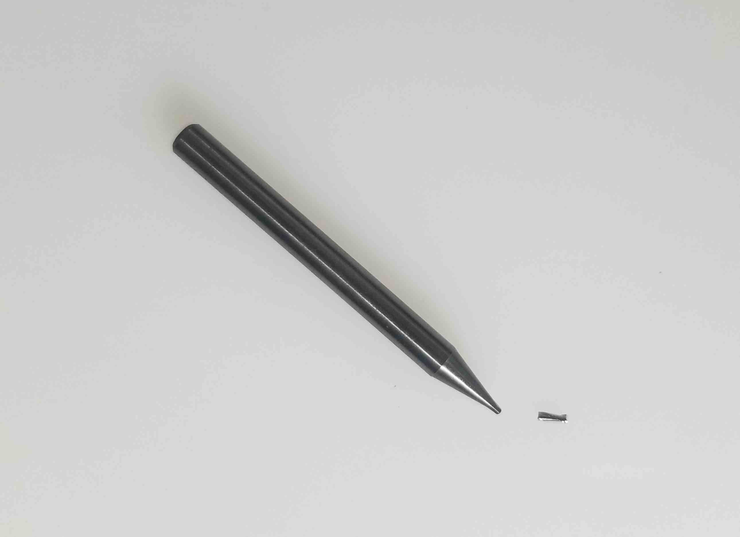
Next up I went through Jake's how-to video on using Clank. I managed to get the controls set-up and running, albeit with some issues from being a Mac user. One troublesome aspect I ran into was controlling the z-axis. To do this on a Mac keyboard, you press the Z key and then can use the up/down arrows. For the controls, the amount of movement for each key stroke can be changed in an x/y/z box in mm/key stroke. I had the x/y movements sent to 10 mm/keystroke since I was moving to position quickly. I had the z movement set to 0.1 mm. Unfortunately when I pressed z, although it did in fact move in the z-direction, it used the y inputs instead of the z inputs. This meant far too big of a downward z-movement, and, you guess it, a broken bit! Luckily it wasn't one of the expensive 1/64th bits but all the same, a bit of a disaster for a first move!
Characterizing Clank
Once the controls were sorted, I needed to characterize clank - how close can my traces be and still have good seperation, how thin can my traces be? I used the provided .pngs for a gauge shown here.


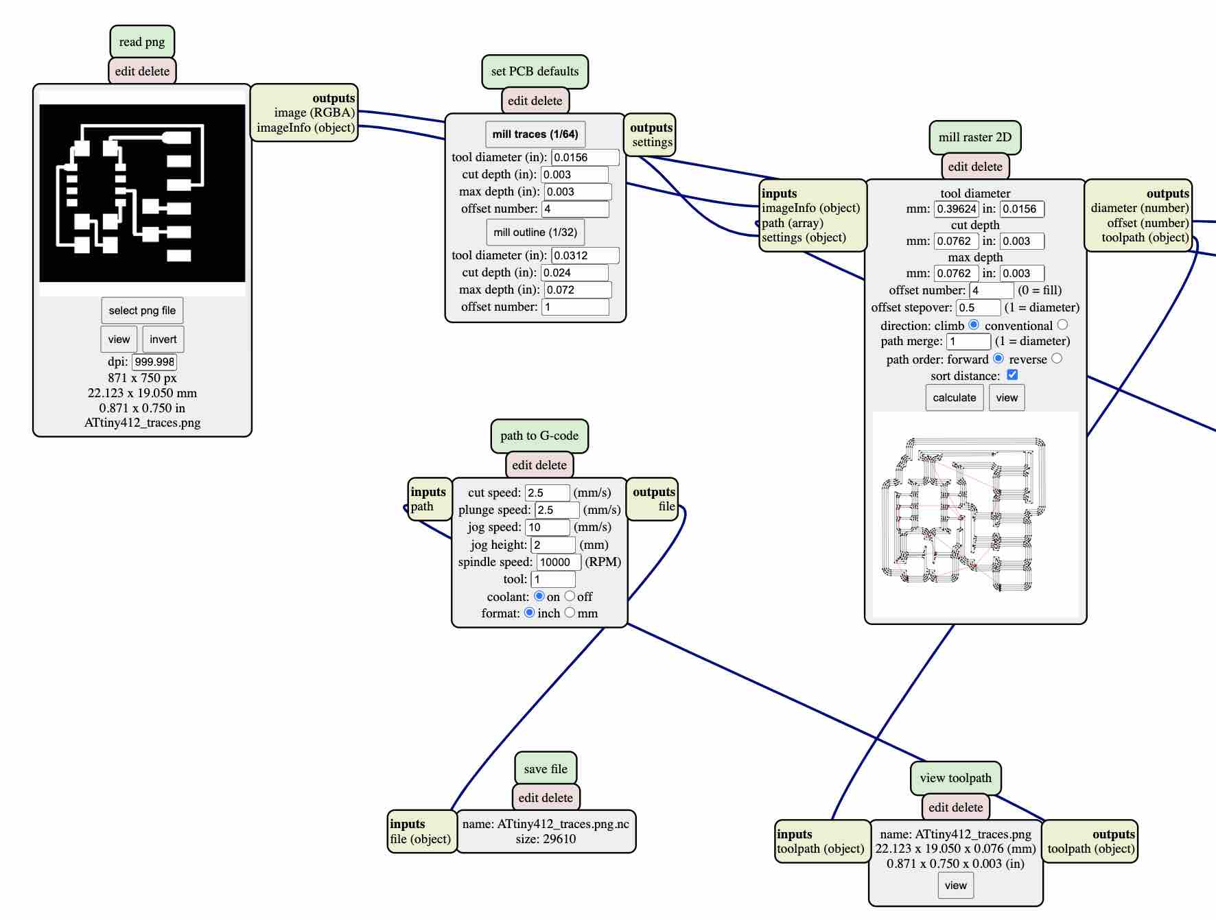
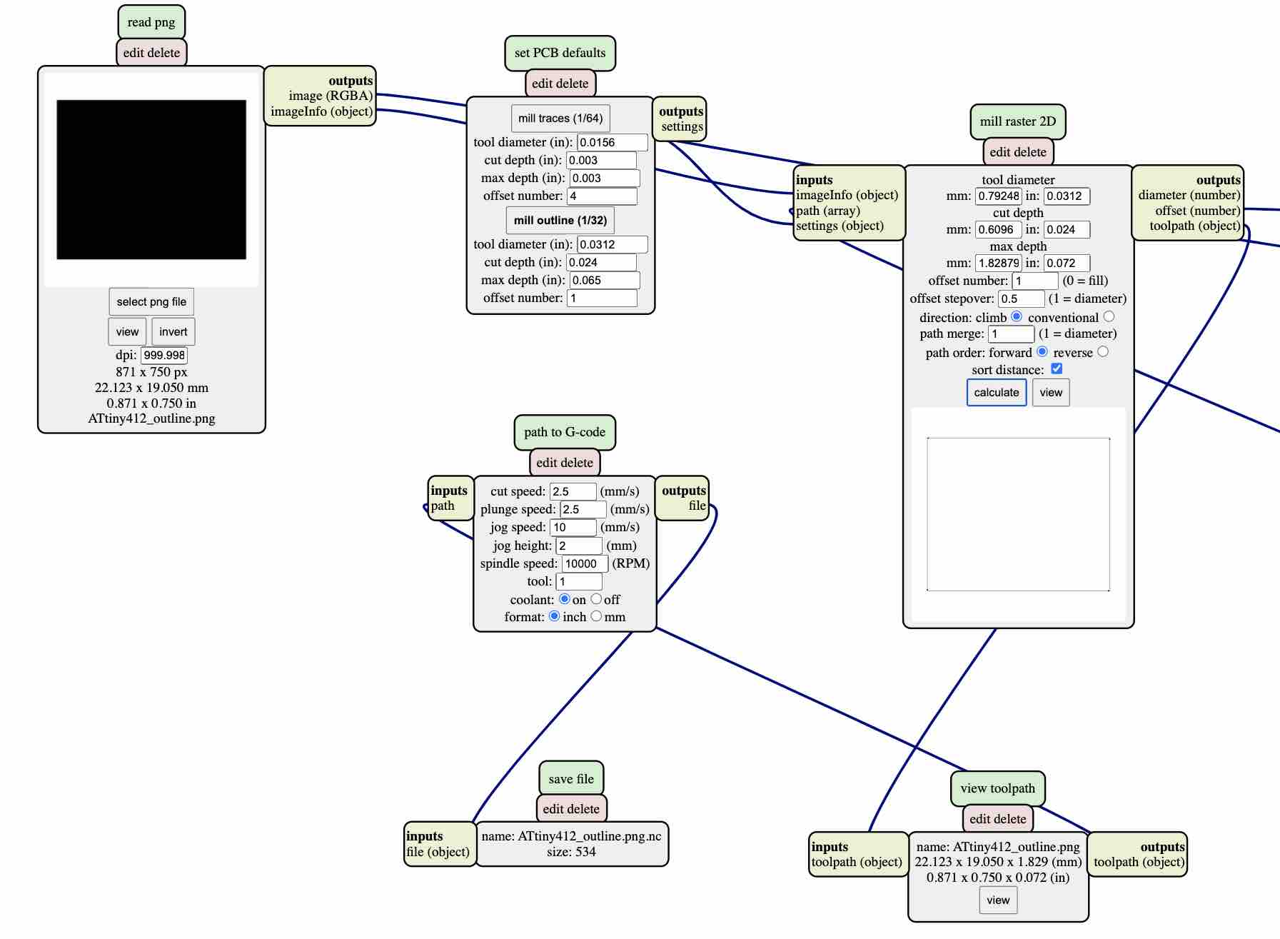
I then used mods to make the g-code that Clank uses to run these. The settings I used were for a 1/64" tool (although I used this for the engraving tool as well). I used a 0.0156" tool diameter, 0.003" cut depth (0.003" max depth) and 4 offsets. For the outline I used a 1/32" tool diameter (0.0312"), 0.024" cut depth and a 0.065" max depth.
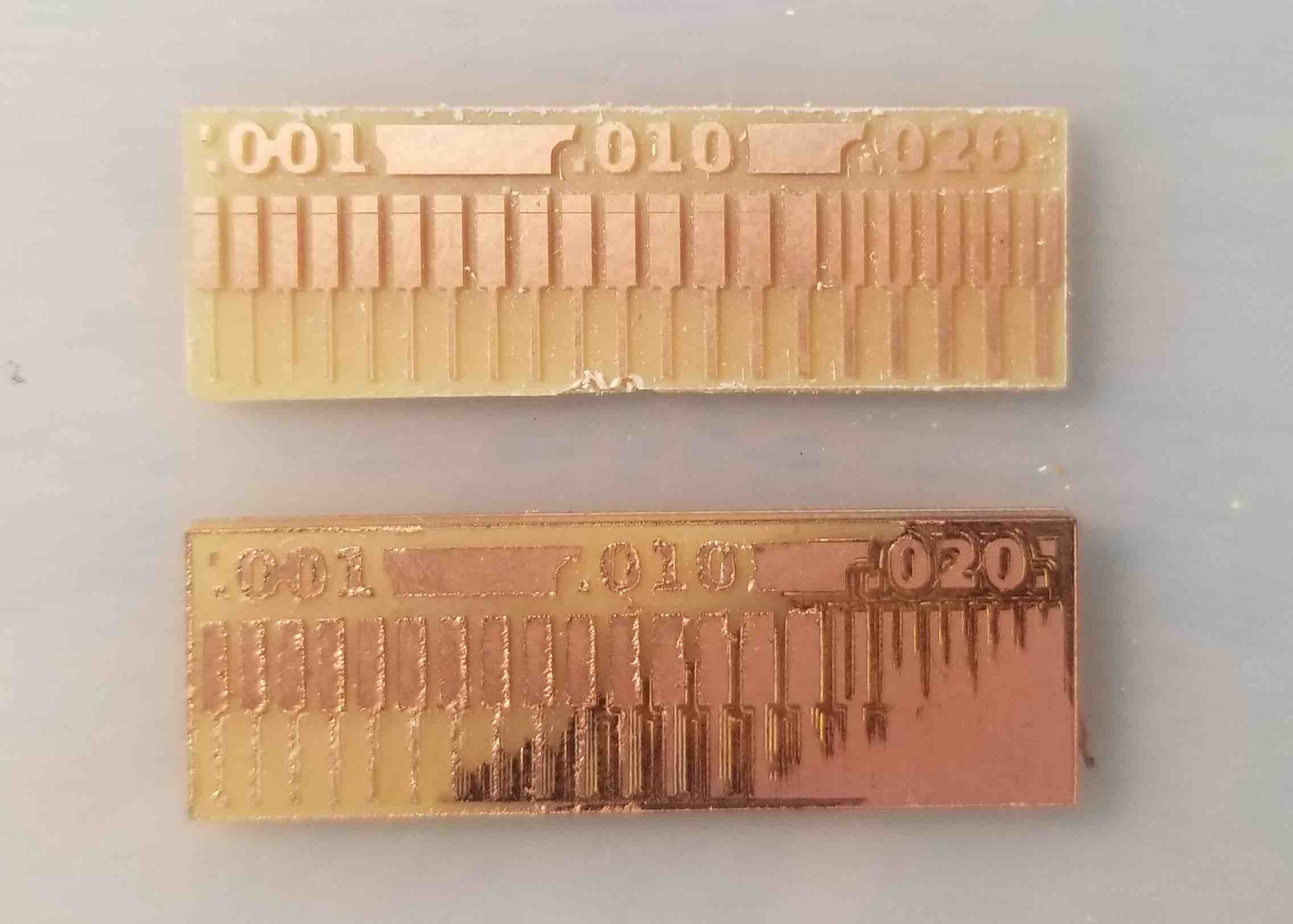
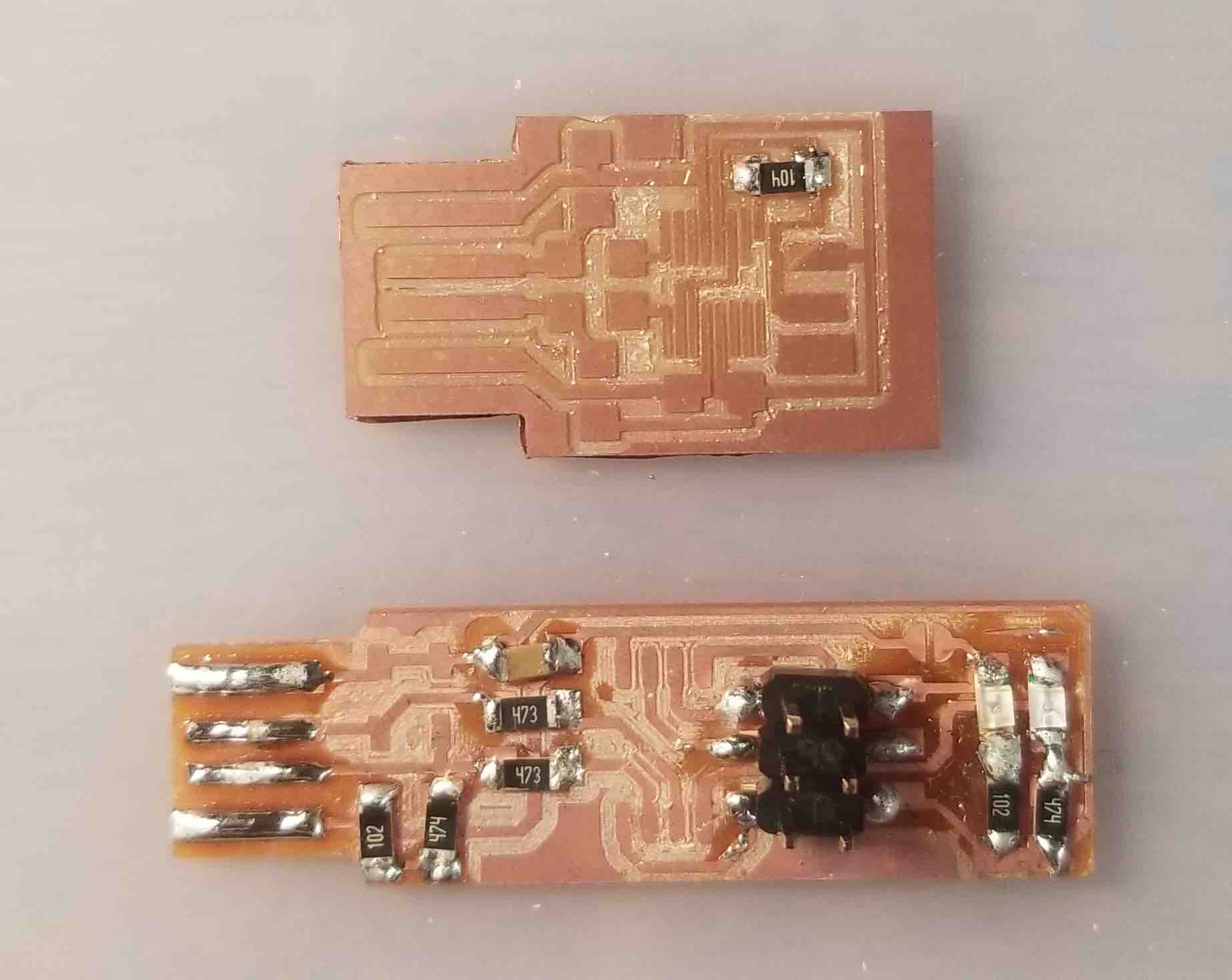
The engraving bit was much cleaner (top in image) at cutting so I'll be using this bit for my circuits. I also found out that my base is very slightly slanted (notice it stopped cutting at the right hand side of the 1/64" board) so I'll add a few extra layers of double sided tape on the right side when placing my pcb to offset this.
Making Cicuits!
Here are some basic instructions for creating circuit boards using clank:
- Make or select a circuit board to print and save it as a png.
- Make G-code for both the traces and the exterior of the board (two seperate files). I used mods to make my g-code for milling.
- Set clank's zeroes on your pcb using the controls with the engraving tip - don't forget to 'unclick' the controls before you set the zeroes
- Load the g-code for the traces and hit run!
- Change to the 1/32" tool and reset your z-zero only - do this by setting the bit onto the pcb, hit 'get pos' and then change the z to 0.00. Hit 'set pos' and you're good!
- Load the g-code for the outter edge and hit run (this part is loud...)
- Done! Now go stuff your board.
I ended up making 3 circuit boards. From the first one was the USB-FT230 board.

I realizedd that when creating the g-code of the outline, you need to invert (have the black on the inside). I found this out since the USB section didn't actually fit into the USB slot! I didn't end up stuffing this board since the micro-controller was not included in our kit (and the USB wouldn't have fit anyway).
Next I made the TinyFab.

This turned out great! I stuffed this board despite the fact that I also didn't have the micro-controller for this board (the ATtiny45). I needed to practice my soldering. Here are the two first boards
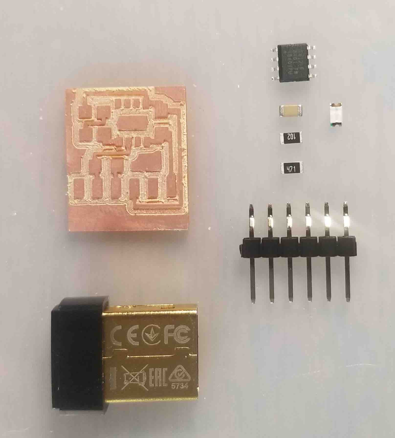
Finally, I made the hello.t412.blink board for the ATtiny412. I included the parts that I'll be stuffing as well, and a USB just for size reference.

Stuffing!
No, not the turkey variety. This was my first time soldering a circuit board, and I gotta tell you, if you have shaky hands or less than superhuman eyesight, this game is not for you! The average part is around 2mm x 1mm and they do NOT want to stay put. Here are a few things that I learned from stuffing my boards:
Hopefully I'll add to this list as I figure out how to solder better myself!
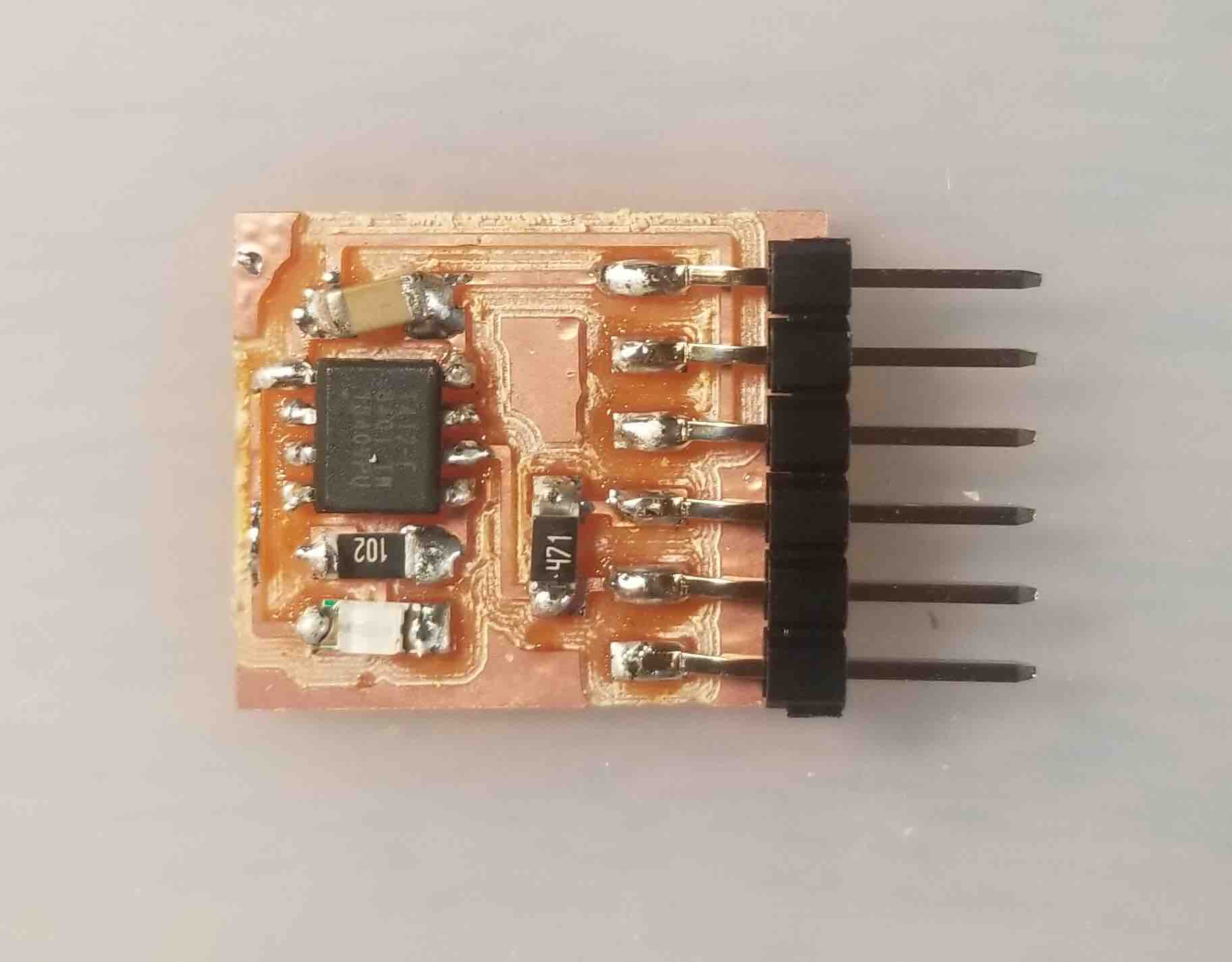
Here's the final stuffed board! (Look at that poor sad capacitor... so crooked)
Source code