[08 Input Devices]
Circuit boards are hard! Seriously, the parts are incredibly small, there's both physical and software debugging, and Clank can be very cranky, which doesn't help. So this week, we learned about input devices. The goals this week were to test a board with our oscilloscope and to make a circuit board that has an input device. I decided to focus on my final project since Nov. 20th is coming up very quickly which means lab access will end very soon! Just a reminder, I'm now making a VR glove!
The input
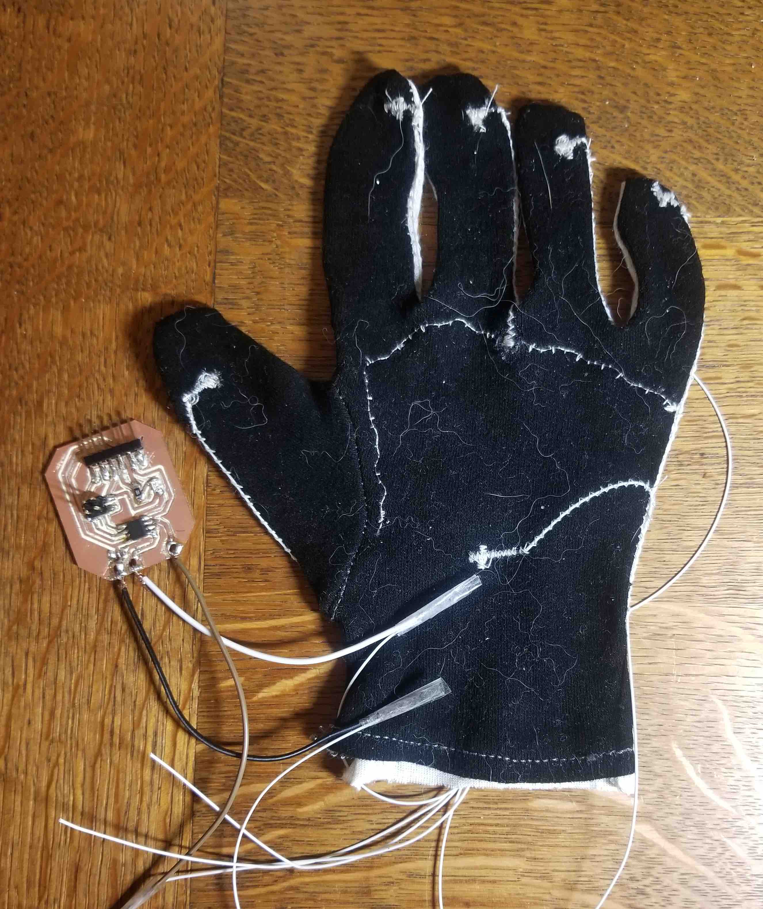
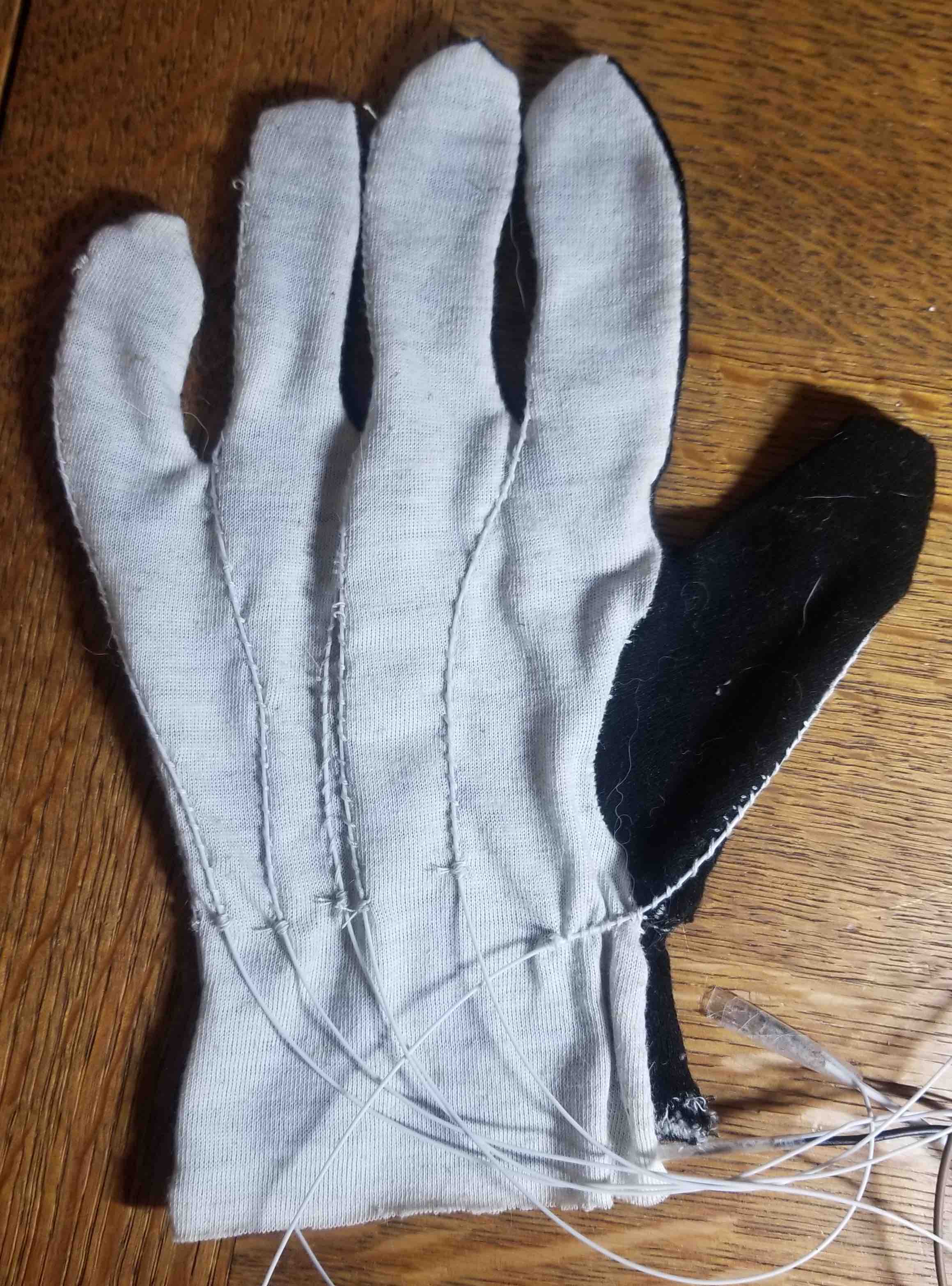
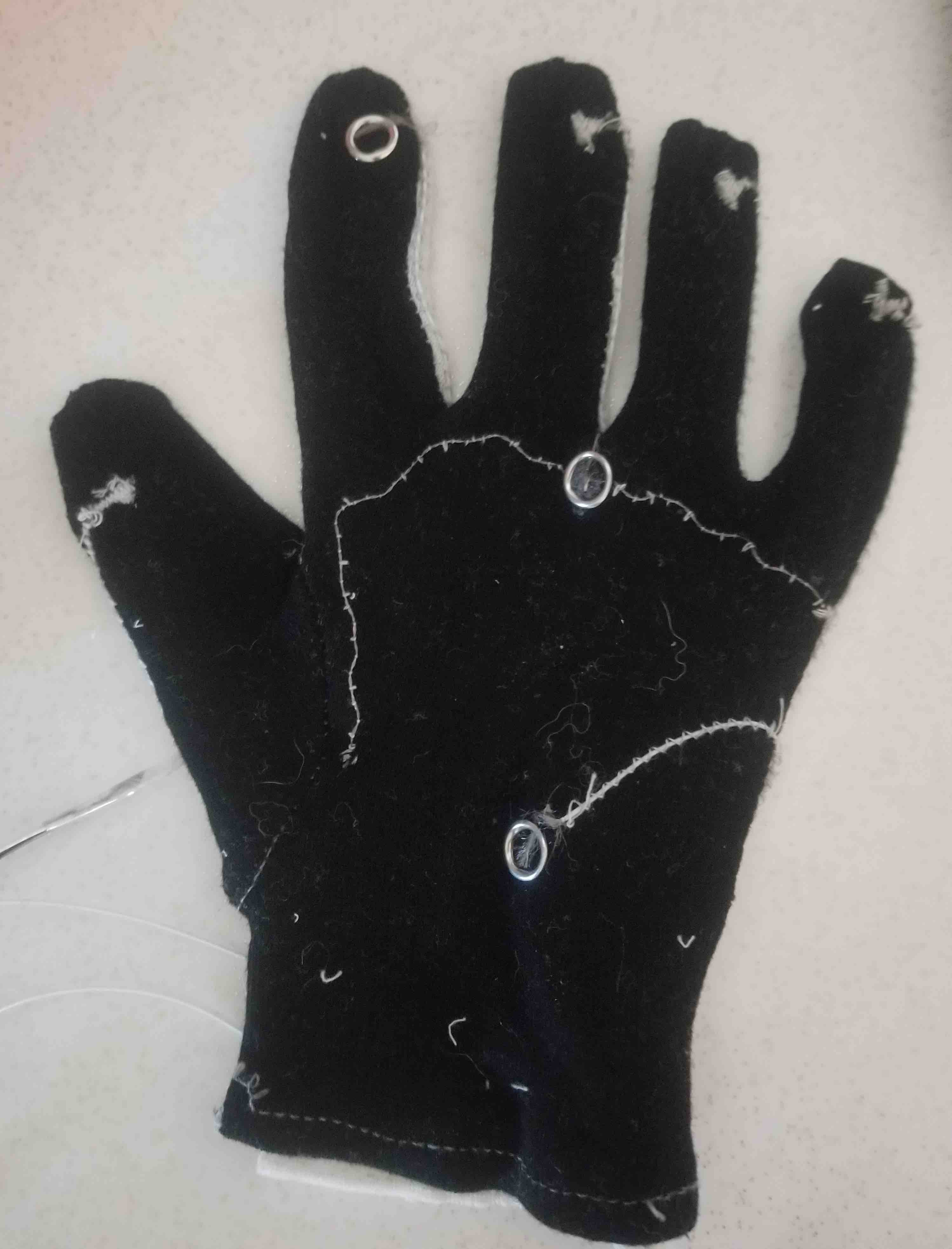
Each finger in my VR glove acts as a voltage divider. Power goes into the finger tip and there is a common ground on the palm. There is a single central node (actually a line across the base of the fingers sewn in with conductive thread) that reads out a voltage. Depending on the percent of the original voltage fed in at the tip tells me if the finger is flexed. For the final project I'll rotate through the fingers reading in the voltage and can monitor finger movement this way. For this week I'm only looking at one finger.
The board
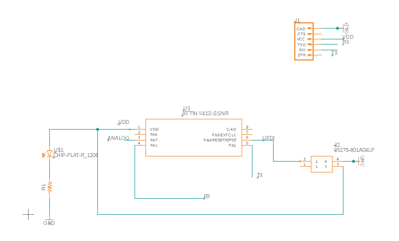
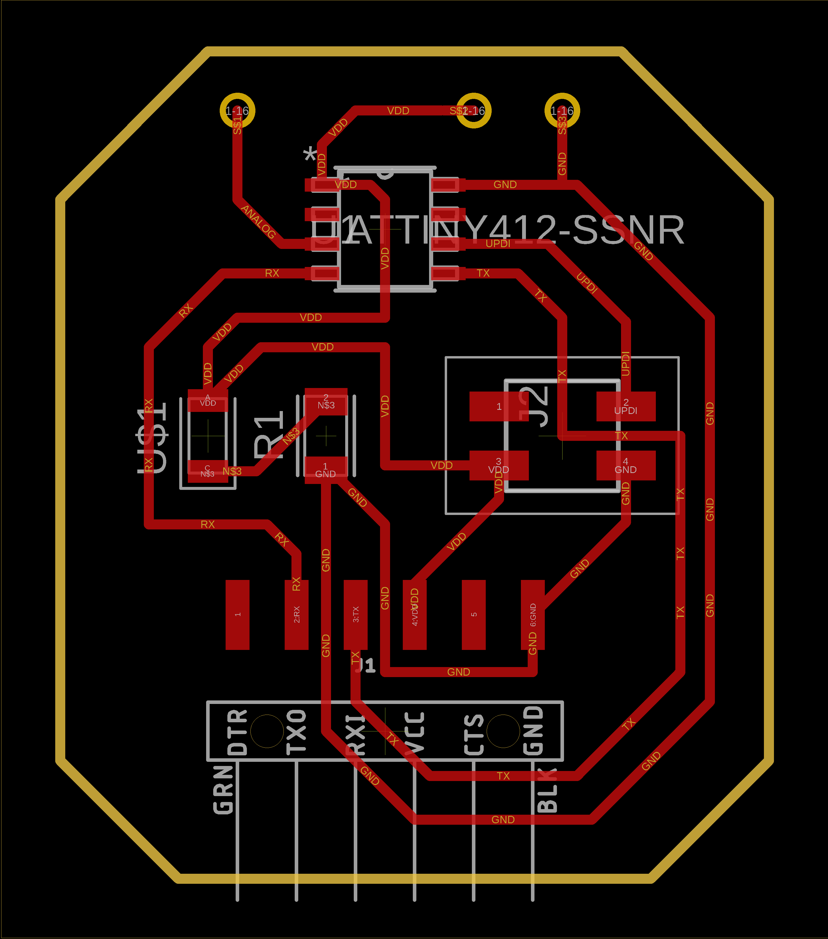
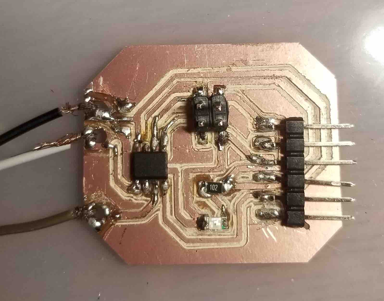
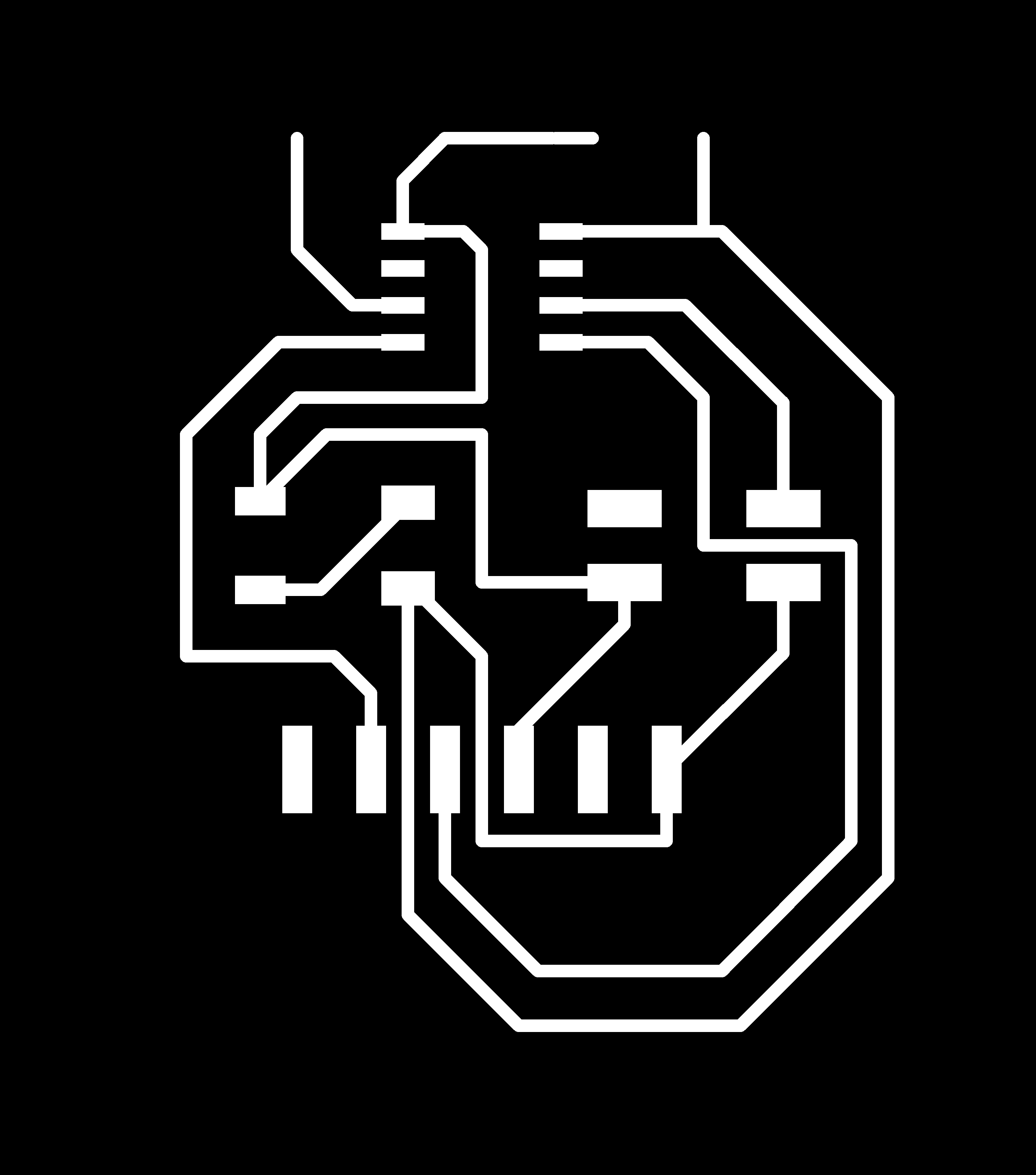
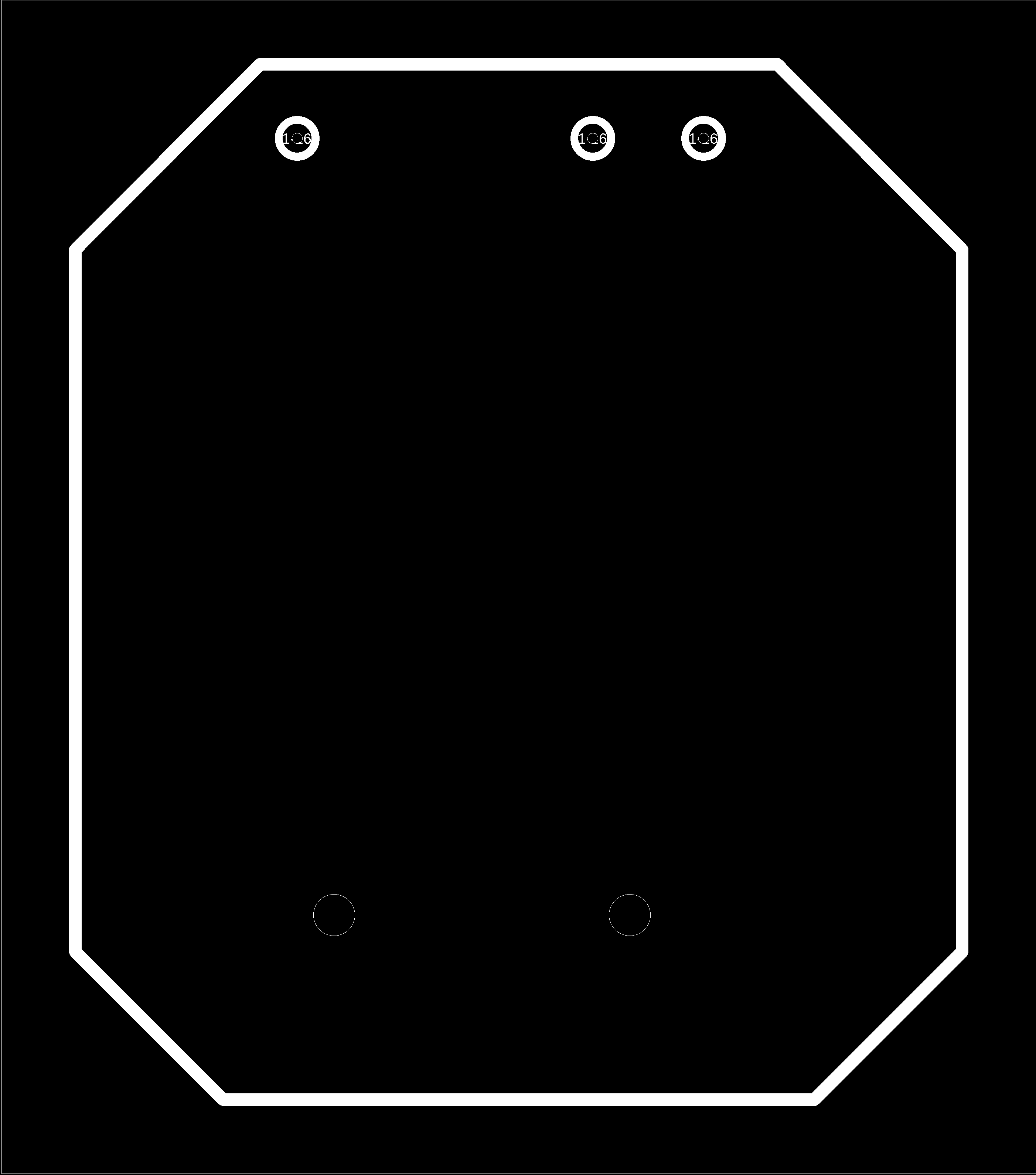
For this week I designed a circuit using the ATtiny412. One of the main challenges this week was connecting the wearable conductive fibers to my board. I needed 3 connections, power, ground and analog readout. I decided to go with a through hole and to wind my fibers through the hole. Here's my cicruit schematic and board design.
I did go through a few iterations of this board, some important things to note here:
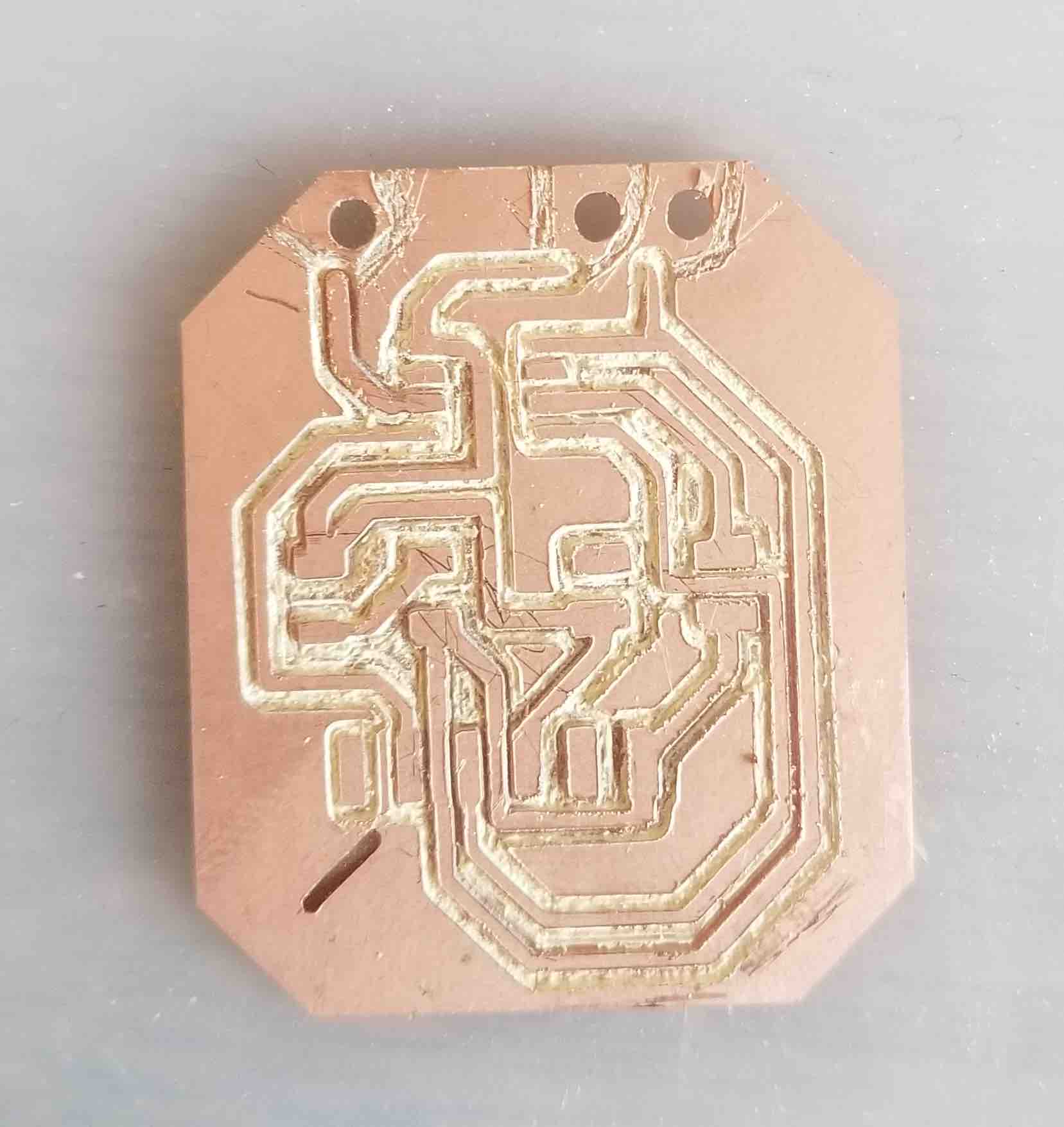
Notice that with this final board I had just changed my engraving bit to a new one and the tip was too sharp and I ended up needing to debur the board. I also couldn't figure out how to draw a trace around the holes so I cut these out myself.
The code
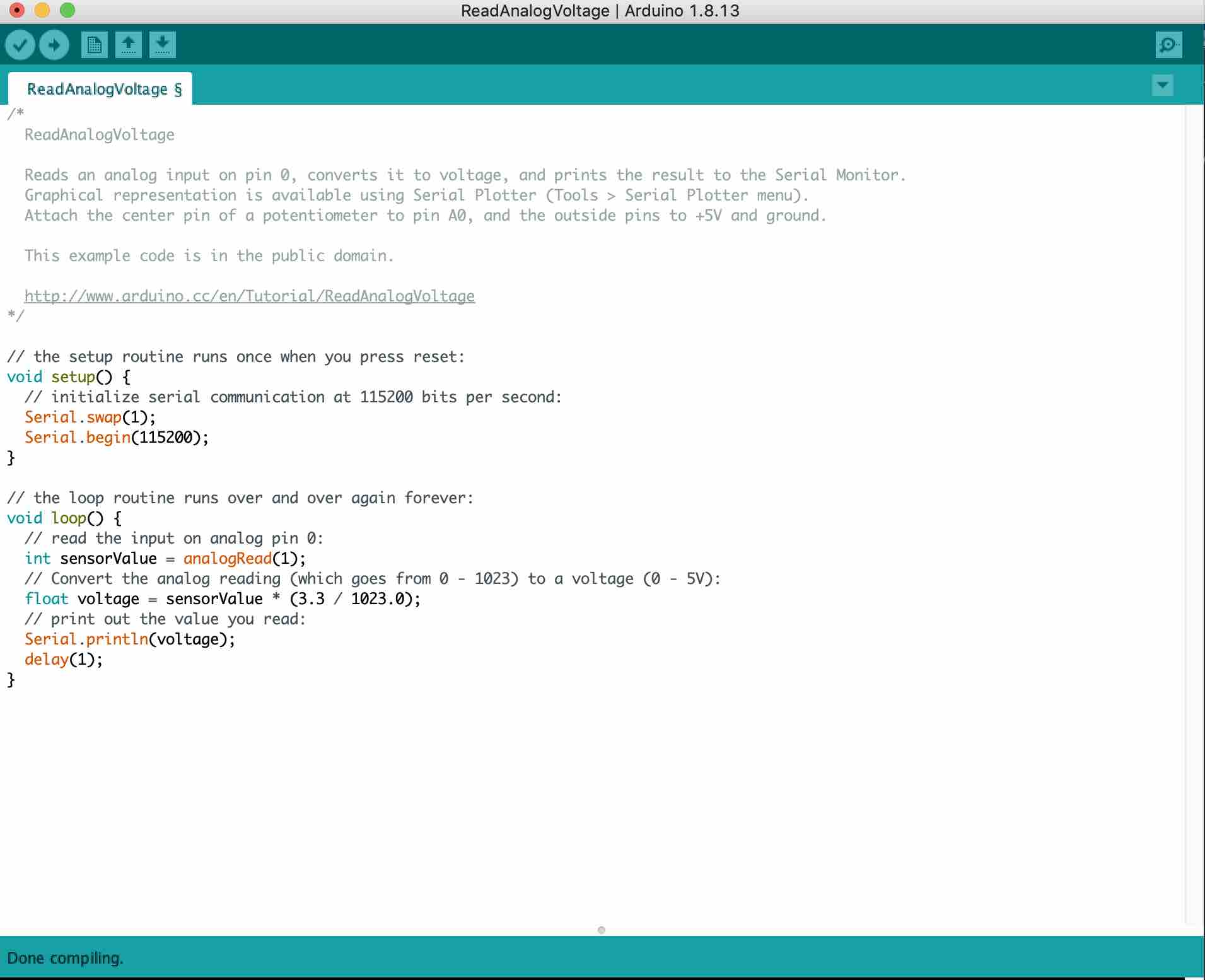
the code was very straightforward. I started by using the Arduino Example code for the Voltage readout (ReadAnalogVoltage). I changed a few things. First, I made sure that my pin matched the Arduino pin schematic. When it reads the voltage, it outputs a value between 0 and 1023. To output a value that was acually meaningful I sclaed this value to the 3.3 V maximum that I would be using as my input. Here's the code!
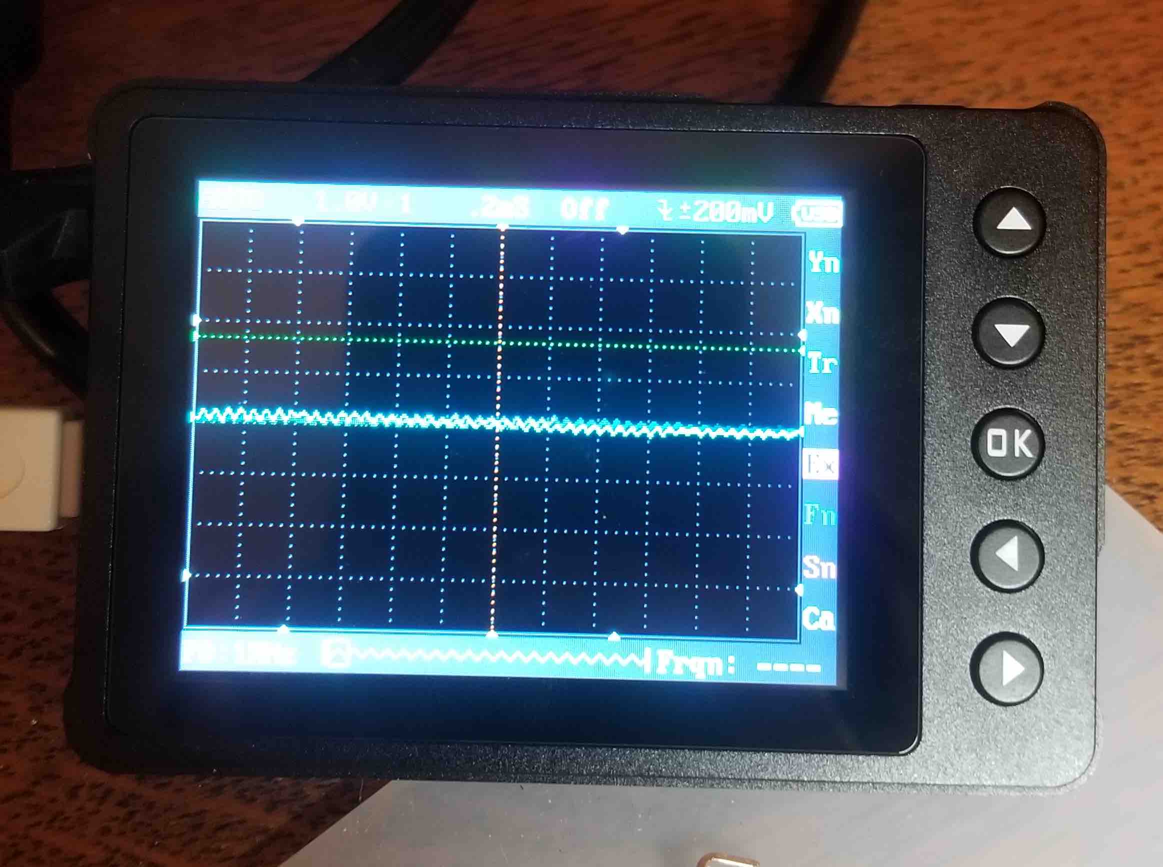
Checking the osciloscope
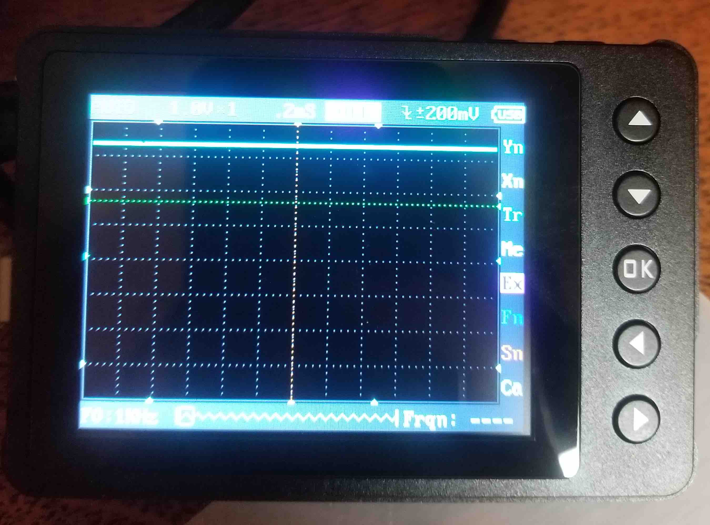
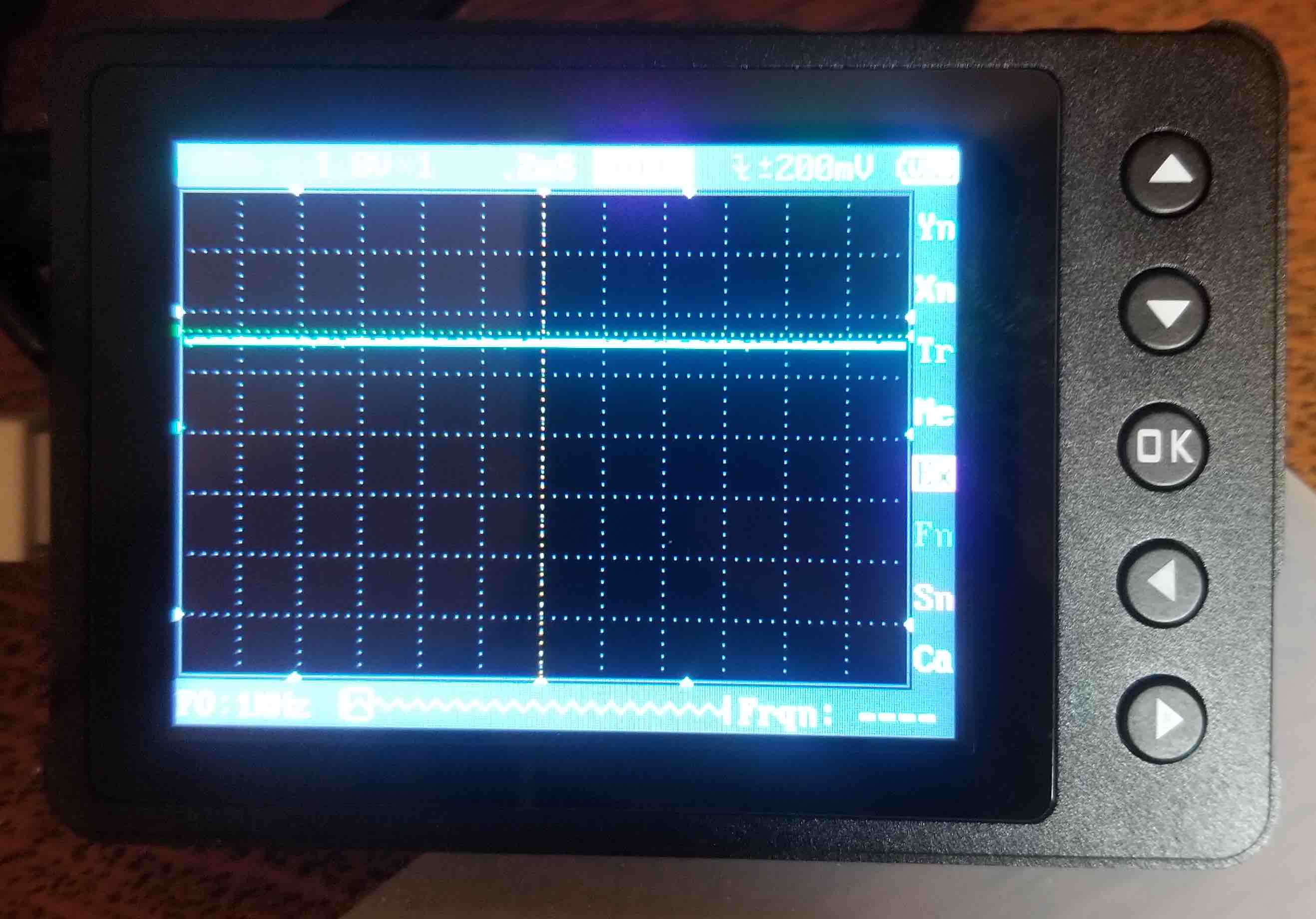
I had to redo my board a couple of times and had some issues with soldering. The oscilloscope came in very handy to check that I was getting the outputs I was supposed to from the pins I was supposed to! In the next sequence of picutres you'll see the zero level, then the voltage input (what's going to the fingertips) and the voltage output (what I'm reading from my pin). You'll notice that the voltage is roughly half in the second one. Since the glove was laying flat for this, that made sense!
The results
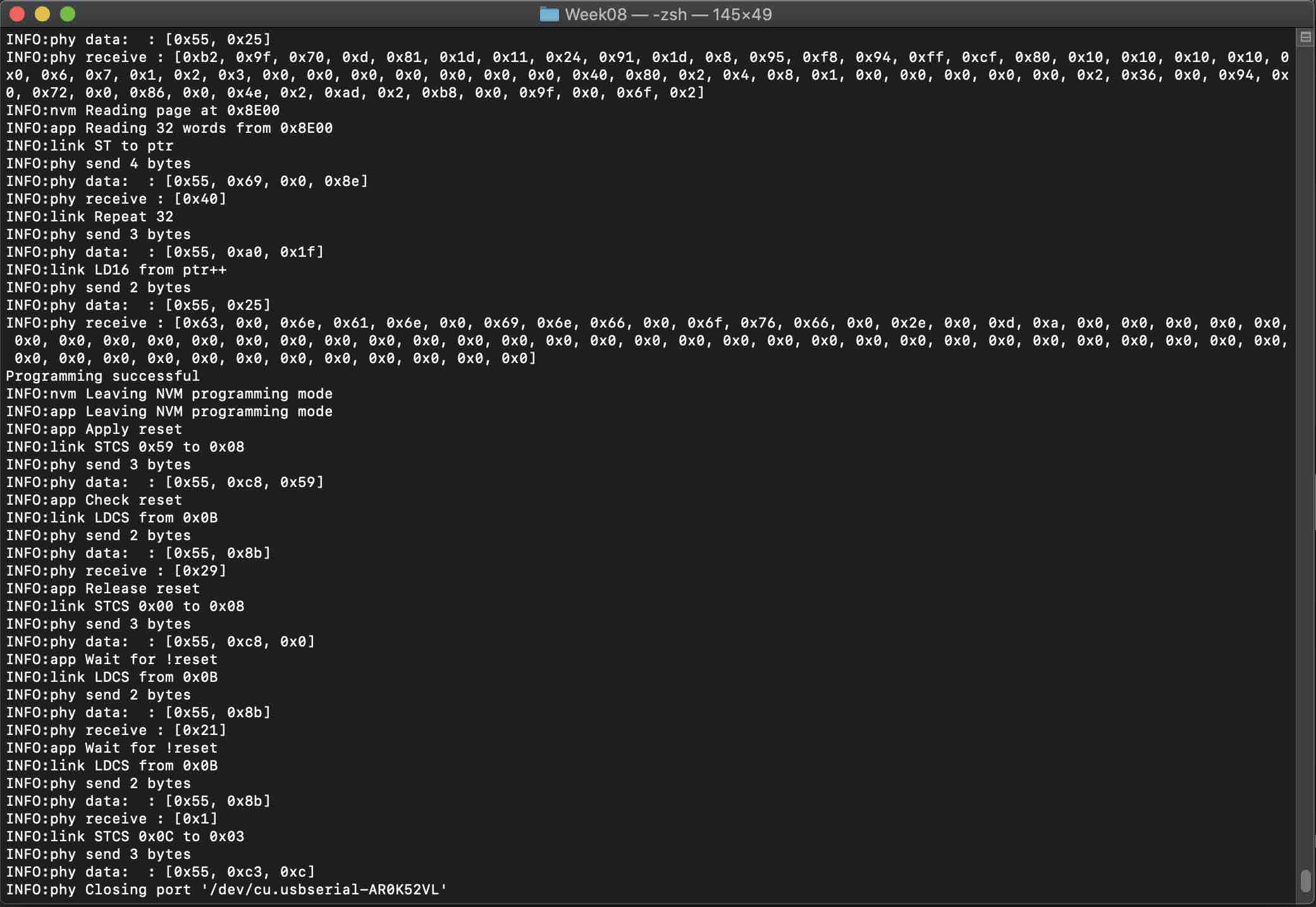
So this section still needs some work - aka I need to learn out to do output displays! I managed to program my board and it ran! So very exciting! However, because this is not an Arduino board (its an Attiny remember?) I couldn't use the Serial Monitor in Arduino. I downloaded pySerial to visualize the data but am still learning how this works. I'm not proficient using Terminal so I still have some learning to do. Here's what the functioning Terminal output looks like thought!
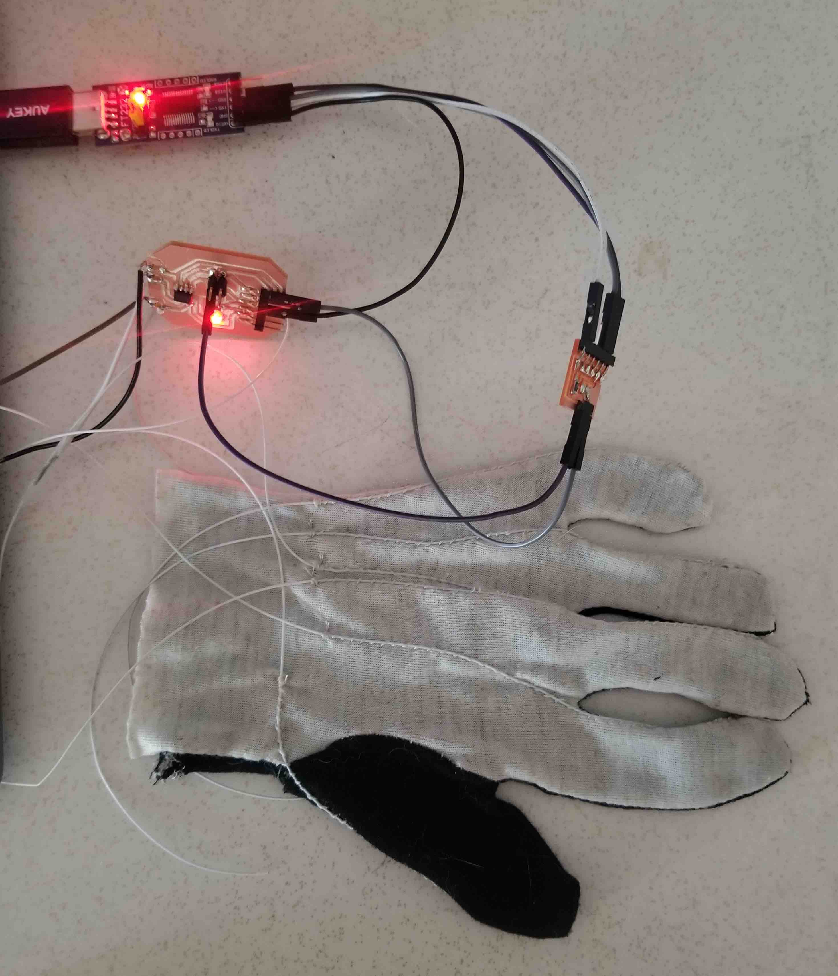
Here is the whole setup with the little power LED all lit up!
Update!
Silly me, I didn't realize that once I had programmed my chip, the outputs would just be read into the Arduino Serial Monitor without needing to write any new command lines in Terminal. I ended up using the analog value to display (goes from 0 to 1023) instead of changing this to voltage since this gave me a much bigger range to work with. I then used 'Serial.print("300 500")' to make is so that the Serial Plotter showed me a nice graph of my changing voltage. I found that the wires didn't have great connections at the nodes, so I took out the sewn pads and used snaps instead to get a better connection.
And here is a quick little video of the finger movement changing my analog input.
The Source Code