[09 Output Devices]
Now we've covered input decives, it's time to get to all those fun displays and motors and lights and and and.... Output devices! We had two goals this week. One was to design a board with an output device and to program it to do something with a microcontroller. The second was to measure the power consumption of an output device. I wanted to try a few new things for this week so I went with two different designs (mainly because one was very simple just to try out the vinyl cutter and batteries! You'll see.).
Vinyl cutting a light bulb
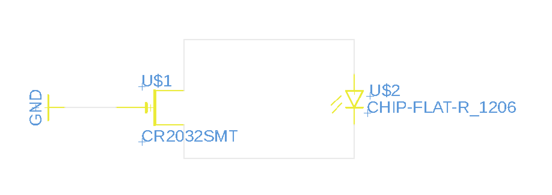
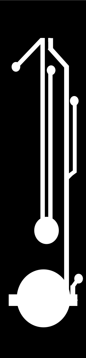
So my first project was so that 1) I could try out making a circuit on the vinyl cutter and 2) I wanted to power something using a battery. So, I designed a very simple circuit to light up a little LED, but I made it so that to close the circuit you'd have to fold the board. Its basically a bookmark that can fold into a tiny reading light. Here's the simple circuit design and the traces I used (no outline since on the vinyl cutter you can stick your circuit onto any old shape afterwards).
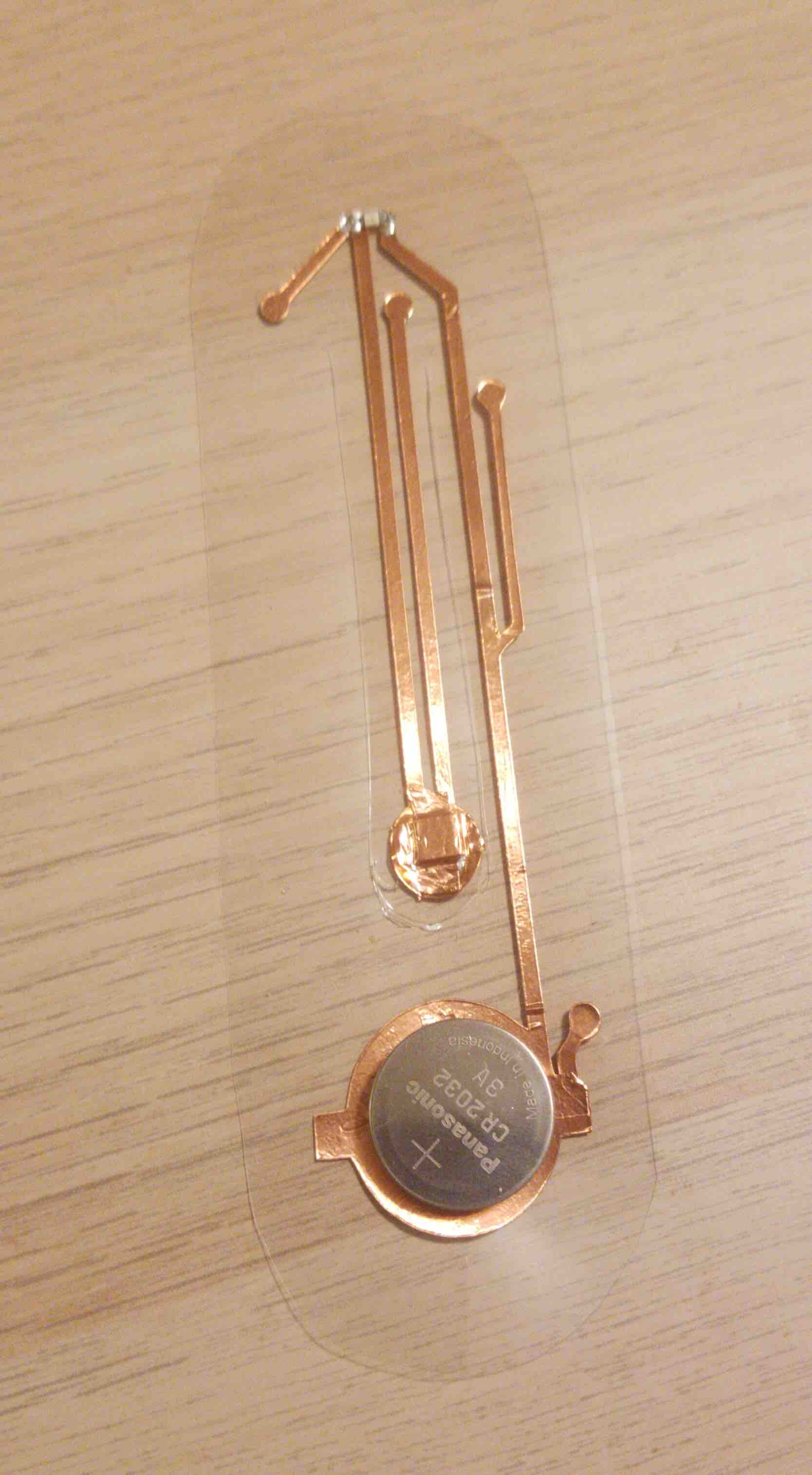
Some important design rules. The first print I did, the traces were WAY too skinny, almost fiber like. And I hadn't nailed down the speed/feed for the vinyl cutter yet so they peeled off and made a bit of a mess. I found 2 mm traces worked great. For the printer settings I used:
And don't forget to make sure you aren't doubling up on your traces! You can do this by following these steps:
- Highlight traces, right click and hit 'Ungroup'
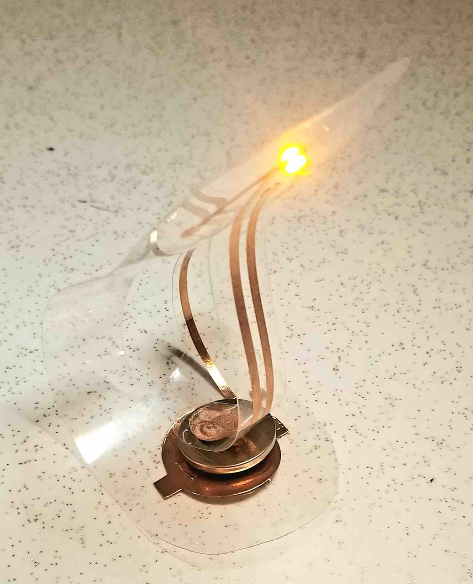
Once printed, I stuck the circuit onto a clear plastic sheet and cut out the outter shape and the bendy part to close the circuit. Here's the final product!
Join the light side!
So, while my bookmark was fun, and technically an output device, it didn't use a microcontroller. For this, I decided to do something for my newphew, who is absolutely OBSESSED with Yoda (he was baby yoda for Halloween). I wanted to make a Yoda who's light saber lights up. And, since this will be a toy, it needs a switch to turn it on and off, and it needs to work on battery (Yay, I get to use something I learned how to do with the Bookmark!). I decided to use an RGB LED for my output device and have it run be in Yoda's light saber. I wanted it to run through a bunch of colours when turned on (I needed something that wouldn't require a computer connection to do something fun).
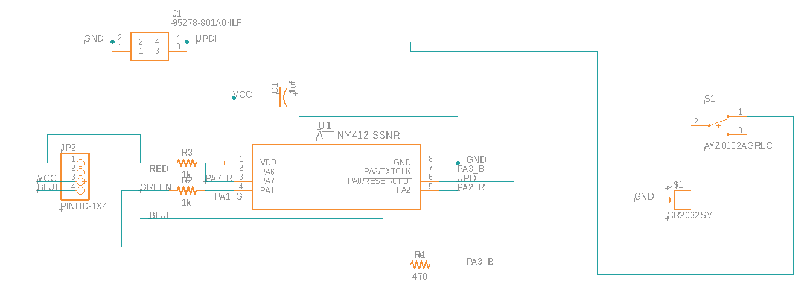
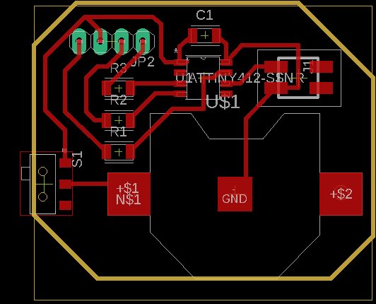
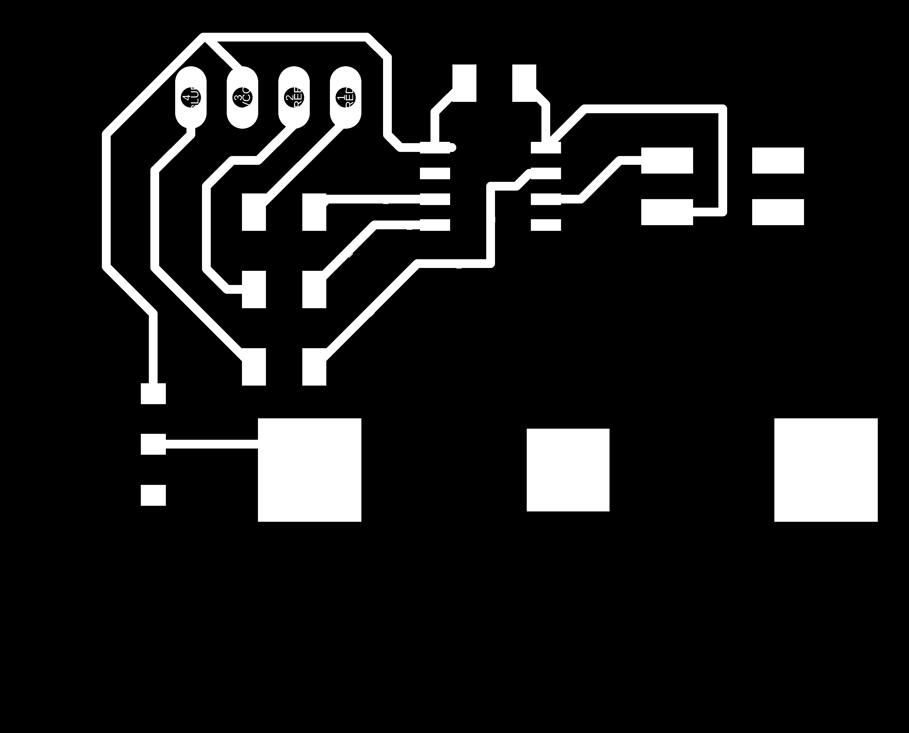
I used a pre-made Yoda that I got from Thingiverse (Baby Yoda). I printed this on the Prusa using no fill (so that I could wire it up afterwards) and supports everywhere (those ears just stick out too far for no supports). Once that printed, I drilled a small hole in his hand to wire up the light saber. Next, the board. Here is the schematic and board design. Note that for the LED I just used holes with outline traces since the actual LED would be wired up off of the board in Yoda's hand. Another important thing to note, I didn't use a power supply pin here. I wanted to eliminate the possibility of accidentally having the battery switched on while plugged into a power supply since this can be dangerous.
Next I stuffed the board and connected the external RGB LED. To connect the LED I made small copper pads at the end of connector wires and soldered the LED onto these pre-made pads. This was WAY easier than the first attempt I made which was to just try to solder the wires onto the LED pads (which are about 0.2mm wide) individually. I also used appropriately coloured wires since once I fed these through the hand it was next to impossible to tell which wire went where.
A few important notes here for trouble-shooting a board:
Programming Light Sabers
I used Arduino to program my RGB LED. Making sure to use the Arduino language pins for my Attiny412 I wrote a code that would have the RGB LED run through a series of colours. This came from an Arduino tutorial. Here is my final code:
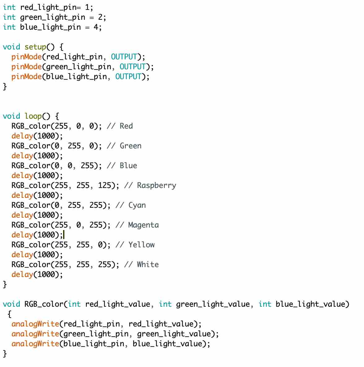
I used my mini programmer and serial adapter to program Yoda's light saber, then disconnected and tried it out! (This did take a number of tries while I was debugging my board -- hence all the notes above on how to fix the board!)
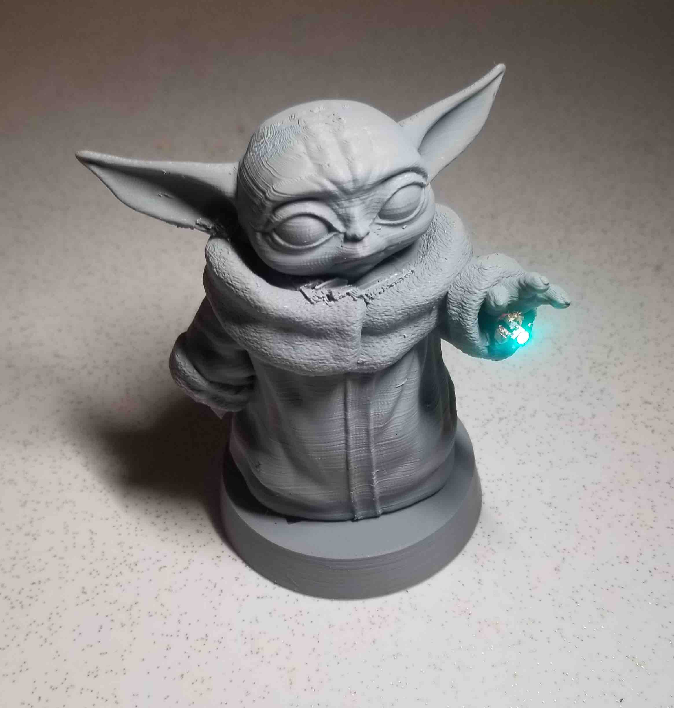
I still need to add a little light saber (I'm going to use a clear pen tube). But I am pretty pleased with how this turned out!
Powerful forces
For the second part of the project we needed to test the power consumption of our output device.
Voltage is measured in Volts and is measured in parallel to the device. Resistance is measured in Ohms and is measured in parallel to the device. Current is measured in Amps and is measured in series to the device. For the RGB LED I measured 2.32 V across the LED and 5.21 mA. This means the LED has a power consuption of 12 mW.
It was very interesting to note that it was actually challenging to do this because the light was programmed to turn on and off and had different colours. I used the same resistors for all colours but you could technically change the size of the resistors since different colours have different brightnesses. You could make the brightnesses all the same if you changed the resistances to match what they needed. Interestingly also, when measuring the resistance across the LED, when the light first comes on for a colour the resistance is highest, then it slowly drops, when the light turns off, there remains some resistance (470 Ohms to be precise!) because of the resistors.
I also measured the LED for the bookmark. This had a voltage of 1.95 V. I measured the resistance in parallel and found 7.55 M \ohms. Using the equation I = V/R we know that . So we know then that the power consumption of the single LED is 0.5 mW.
The Source Code