[06 Embedded Programming]
Now that we'd designed, milled and stuffed our own boards, it was time to learn how to actually make them do something. You think that little power light that comes on when you plug in your USB key is something simple? Ok, well the code itself to do that is, but getting there is not! Its like trying to get two people who speak different languages to communicate an abstract thought! So we need a translator! The way this works is that we write a code (using C, C++, etc.), this is the set of instructions. We then compile that code using an Arduino IDE, which spits out a .hex file. This file is what we instruct our boards with -- through a compiler (the translator). I'll walk you through it.
Prepare the Software!
First download the Arduino IDE. You'll need to install megaTinyCore. This is a library of ATtiny's that Arduino can then use to help you talk to your board. I had some trouble installing this properly. Here is a link to some different ways to do this, but the one that worked for me was the first one --> Boards Manager Installation.
Next, you need pyupdi which actually flashes the code onto your board. This was tricky for me. In the end I needed to download the repo (that's the link there), unzip the folder into a useful spot. Using Terminal (I'm on a Mac) go to the pyupdi directory where the setup.py file is. Then follow these steps:
Write the code
Now you're ready to write some code! I wrote mine in the Arduino IDE. I used the Arduino sample codes to give me the outline of my code and filled in the blanks. The first code I wrote was for my ATtiny412 board that just has an LED on it. Here is the code:
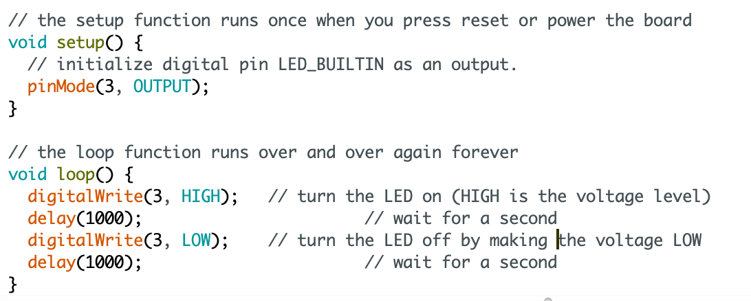
I chose the pin based on this, the megaTinyCore maps of the ATtiny microcontrollers -- I used the brown/blue numbers. In the Arduino IDE I selected Tools --> Boards --> megaTinyCore --> ATtiny412. I also selected the correct Port that my USB was plugged into (check this by plugging/unpluggin and checking what changes). Also important, in Arduino --> Preferences Turn on 'Show verbose output during: compilation'. Now verify/compile the code!
Arduino will now show you its process as it's compiling (that's the verbose thing). Find the part of this that shows you where it output the .hex file. Copy this path and put it into your finder (if on a Mac, use Shift+Command+G to do this). Find the .hex file, copy it and put it into your Sketch folder (you can find this from Sketch --> Show Sketch Folder).
Talk to the board!
Final step, you need to send all of this to your board. Do this in terminal. Here is what you run in Terminal:
python3 ../Programming/pyupdi-master/updi/pyupdi.py -d tiny412 -c /dev/cu.usbserial-AR0K52VL -b 115200 -f TNG_Button_LED/TNG_Button_LED.ino.hex -v
And the breakdown of what that all means:
Hit enter!
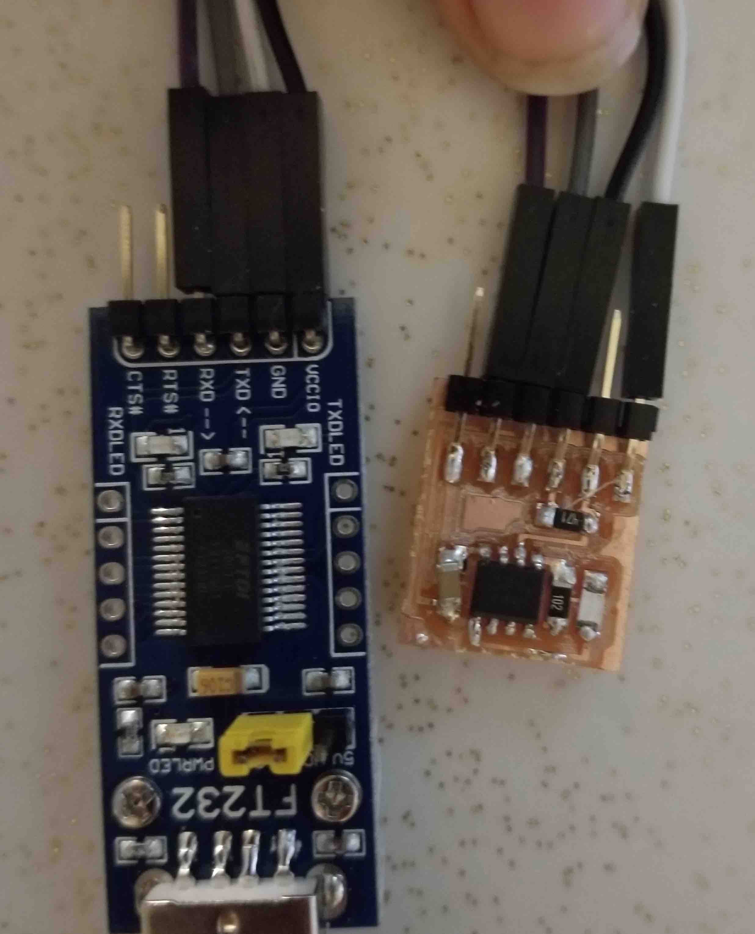
This didn't work right away for me. I actually had my LED on backwards (don't forget, Green means Ground!). And it took me a lot of trouble shooting to get my pyupdi installed properly, but eventually it worked.
The TNG board
Now that I know I can talk to a board, I want to get my TNG board working where bushing the button will turn on the LED. Again, I used the Arduino example (Digital --> Button) to start me off. Here's the code I've written:
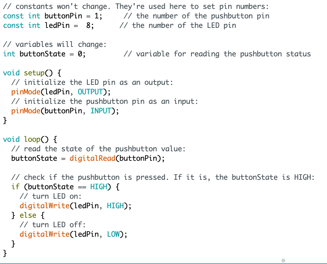
Unfortunately, I can't seem to get this to work yet. I've used my multimeter to check that all the power is running through my board and that I'm getting signals where I should. I'm thinking that maybe I've installed my button incorrectly but am still working this out... come back soon for updates!
UPDATE!
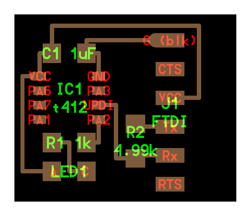
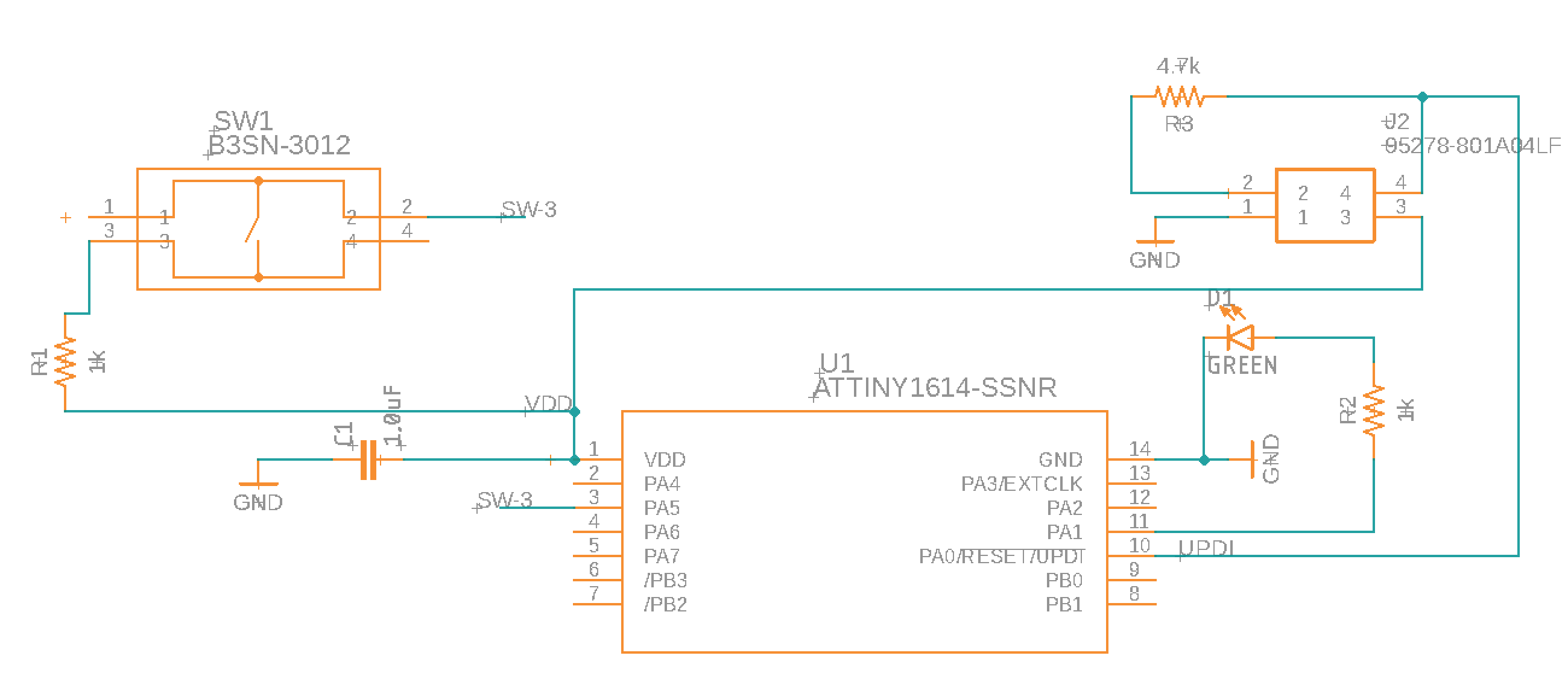
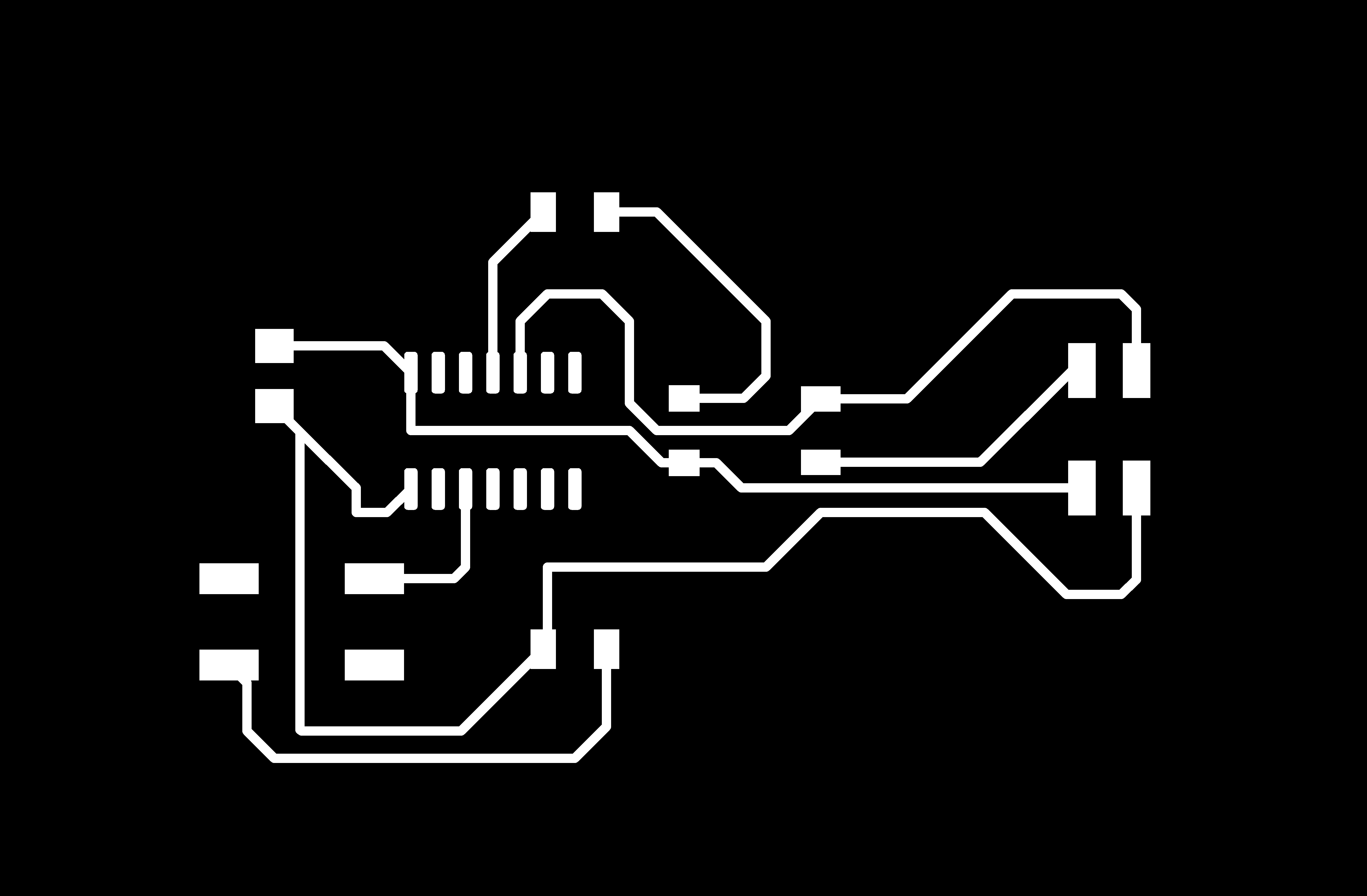
Alrighty, figured it out, and there were a NUMBER of things wrong. The button was incorrectly connected, as was my UPDI pin. All fixed up, here is the corrected schematic and board:
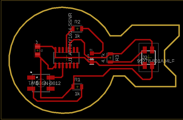
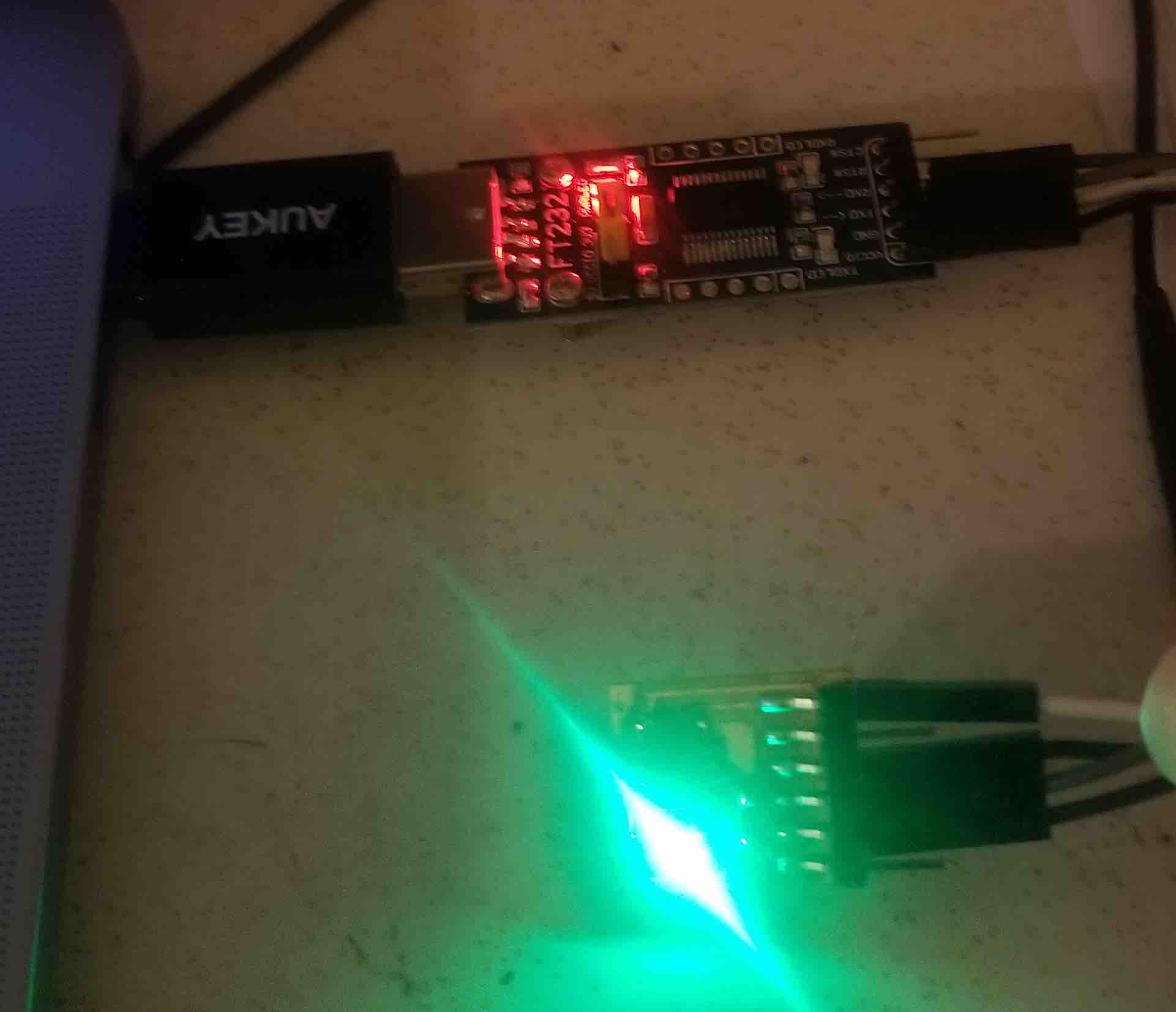
And now, the coding works great and the button lights up the LED!
A bit odd that the light stays on for so long after I release the button, this may have something to do with the fact that I put the pull-up resistor between the button and VCC instead of between the button and the attiny pin - which could mean that the button is giving an erroneous reading when released. Not sure, but something to think about. Either way, I'm glad it finally works (not seen here are about 5 versions of the board with me trying to get this bad boy working!).
The Source Code