[13 Final Project]
Introduction
Materials
Fabrication Drafts
Final Fabrication
Assembly and Visualization
Final Checklist
Source Code
Welcome to the end! This is actually the whole adventure on this page. I'm going to take you through the development of my final project from start to finish with all of the mistakes, trials and challenges that I faced along the way. Documenting the learning process is just as important as the end result, if not more so. This might be my science brain speaking, but documenting is the only way that you or someone else can repeat an experiment, make something again and then, most importantly, make it better! Why learn the same thing twice, right?
What am I getting out of this project
I wanted to pick a project that would allow me to learn the most valuable things for my Ph.D. thesis. This was a difficult choice since I'm working on two projects. The first is the development of a radiation shielding material for spacesuits and incorporating thermal control into this material. The second is integrating a Moon rover's instrument data into a virtual reality mission control centre called vMCC. I considered trying to make something to improve the VR headset for field work, but since my thesis is primarily on the VR platform development and not testing the VR hardware this didn't seem particularly relevant. Given my background is mostly in aerospace and geology (and definitely not materials science) I thought instead it would be great to learn how to work with fabrics and wearable electronics since this has a lot of applicability for my radiation shielding project, and could have applications for the VR hardware down the road (who knows, maybe we'll make a haptic glove for the headset!). Heated gloves are something that are out in the market, and the xEMU (current US spacesuit) has heated gloves designed specifically for mobility and working in this extreme environment, so let me be clear, I'm not reinventing the wheel here. I'm more interested in learning how to use the tools (both actual tools and knowledge tools) to make a wearable technology. Ok, now you know my motivation in this, lets dive in!
Thinking about modeling the hand
In cased you missed it in Week 2's scanning project, I scanned my hand using the Leo Scanner. It was actually pretty challenging to scan something that is moving, even in just a minute way. I used Meshmixer to clean up my scan, mostly using the Sculpt tool which allows you to mold the scan directly, its a very intuitive tool. Here's the final model.
I plan on making a sort of watch band on the 3D printer to hold the temperature display on the wrist. To get the sizing right I'll use my scanned hand in Fusion 360 as my base model. No spoilers here, you'll have to read on to find out how it goes!
Getting help
Another important lesson, not just for HTMAA, but just for life in general: get help! There is always someone out there who is a pro at what you're just learning to do, and often, who is willing to help. Lucky for me, Diana Wagner is an absolute pro in functional design. We chatted about the best way to integrate the thermal filaments into the glove. Initially I'd intended on using a 3D knitting maching (such as the Shima Seiki) to make the glove, but these machines are extremely finicky and have a very steep learning curve (check out Molly Mason's page from a previous HTMAA year). Diana suggested that I start out by hand sewing (or sewing using my home machine) the filaments into a swatch of fabric, trying out different stitch types to see what best works to allow stretch and recovery of the integrated fabric and maintain full hand mobility. I can add these swatches to pre-made gloves in key testing areas use this as a proof of concept. She sent me some great resources to check out for this design process. Check out the glove she and her group designed a glove that uses textile mechanical properties to actively assist hand opening and closing.
Materials
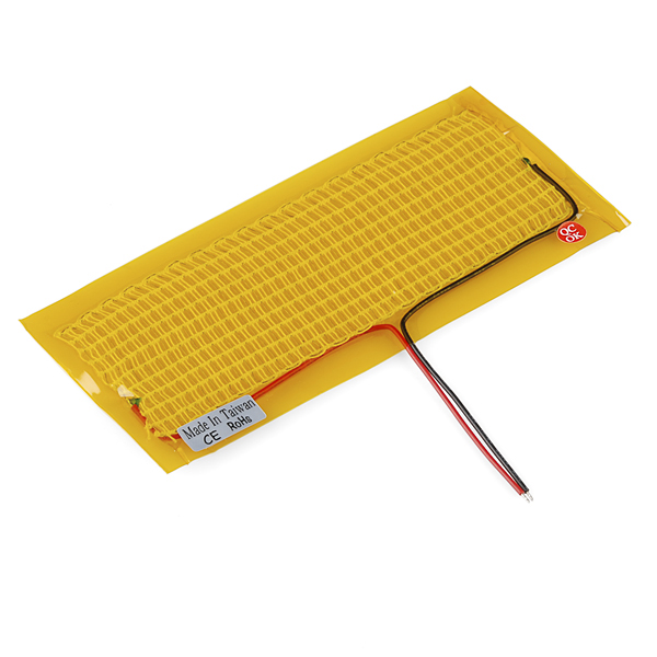
I've started looking into what materials to use for my heating filaments and started with previous HTMAA projects that fell into a similar category. I'm looking at possibly using a pre-made heating pad that was used by to make a heated vest. I'd like to order a few and try taking them apart, varying the size, integrating them into other materials, etc. This will be the goal over the next few weeks. Here's what the off-the-shelf heating pad looks like:
I'll also need to start thinking about temperature sensing and measurement and integrating multiple heating pads into a single sensing and control unit.
After chatting with a few other people (some of the previous years' students) I found out a few things:
Going with the carbon fiber, I did a rough sketch of how I could lay it out (1 pc front, 1 pc back) to avoid the knuckles (in pink) to keep the mobility but have mostly uniform heating.

I then had the opportunity to see some of the work going on in the Media Lab's Responsive Environment teams and found out that Cedric Honnet has developed a polymerization technique that will embue textiles with the capacity to heat! He agreed to help me try his process on a glove for my project. You can check out his PolySense projects, and I will document the process as well.
GAME CHANGER!!!
I've decided to change to a VR glove instead of a heated glove. The second part of my thesis work is working on a virtual mission control for the NASA VIPER rover mission - a rover going to the south pole of the moon to search for water in 2023. I'm working on a virtual reality platform that will be used to control the rover, do path planning, and do analysis on the rover data after the mission. One key element of this work is to enable the scientists to annotate and manipulate the maps and images that we're creating with the rover data. What better way to do this than to actually be able to manipulate things with your hands in the VR environemnt. So, with minimal change (it's still just a conductive fabric we're using, but instead we'll measure voltage changes instead across the fingers instead) I'm going to make a VR glove instead of a heated glove. This will give me the chance to work with Unity as well to display the finger movements. The goal will be to design and produce the glove rather quickly and spend the last chunk of the semester learning and working in Unity. Ok, you may proceed.
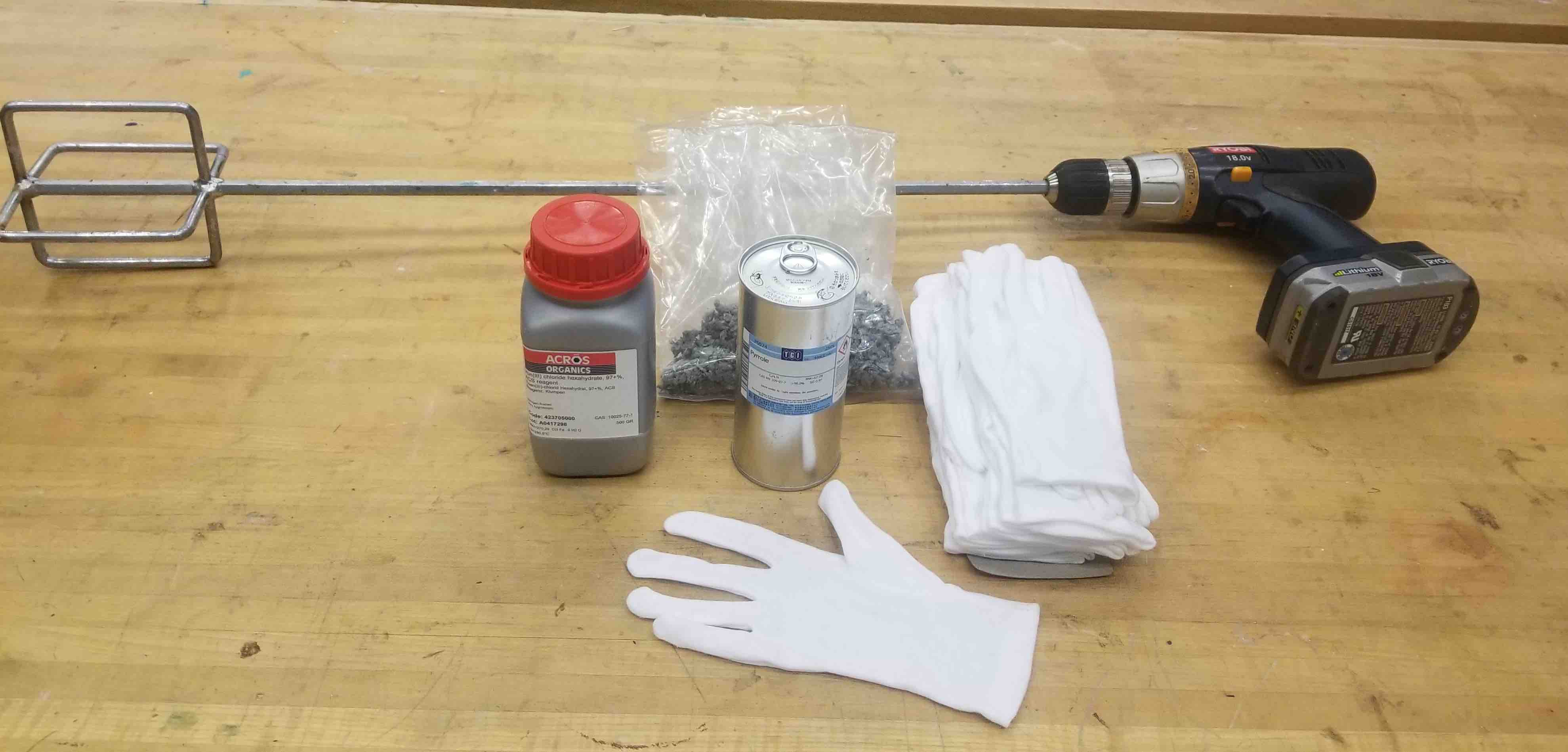
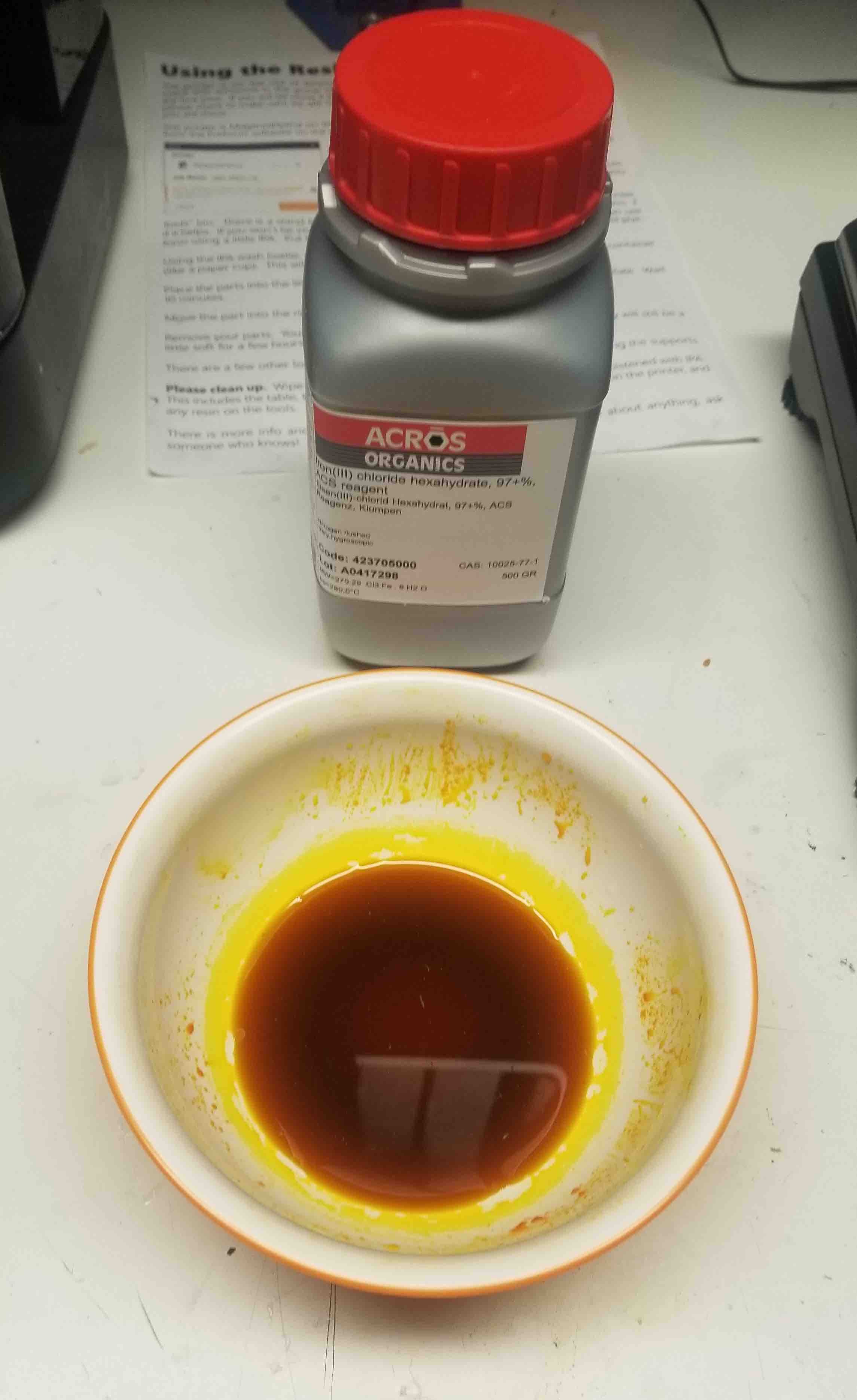
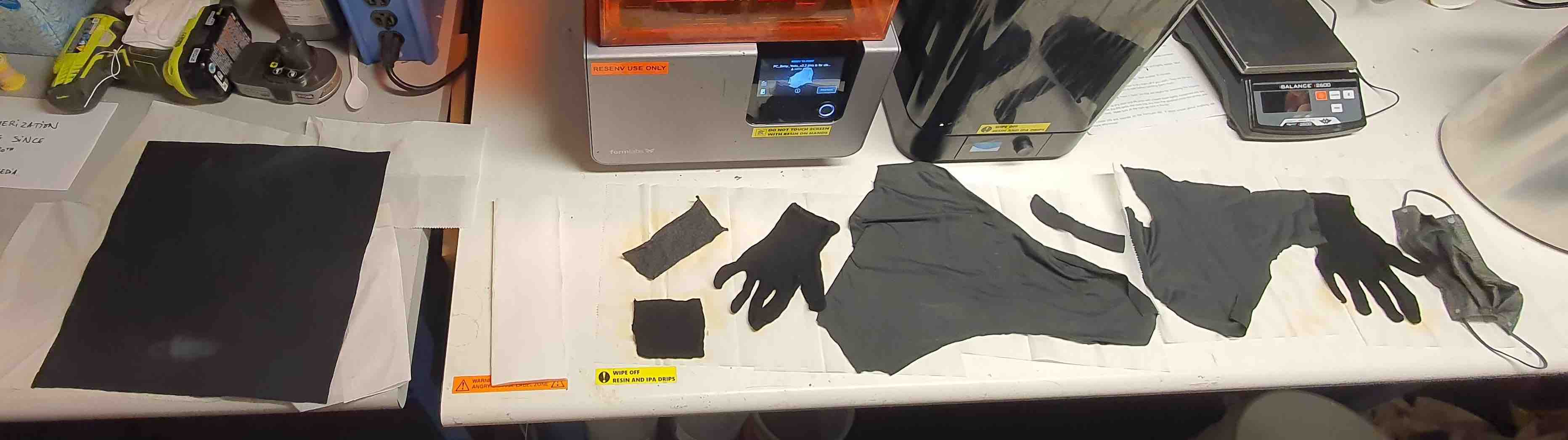
Cedric and I went through the polymerization process, which I'll describe below, for a pair of cotton gloves, a neoprene type 'lofted' material, some stretchy synthetics and a face mask (beacuse why not). Here are the details of the process:
- Weigh the materials (37.8g)
- Measure out sufficient water to fully cover the material and allow them to move around (do not wet the material yet!) (x = 3000 ml)
- Add x/250 ml of pyrrole to the water (12 ml) and mix - careful, the pyrrole is toxic like a strong soap, where gloves
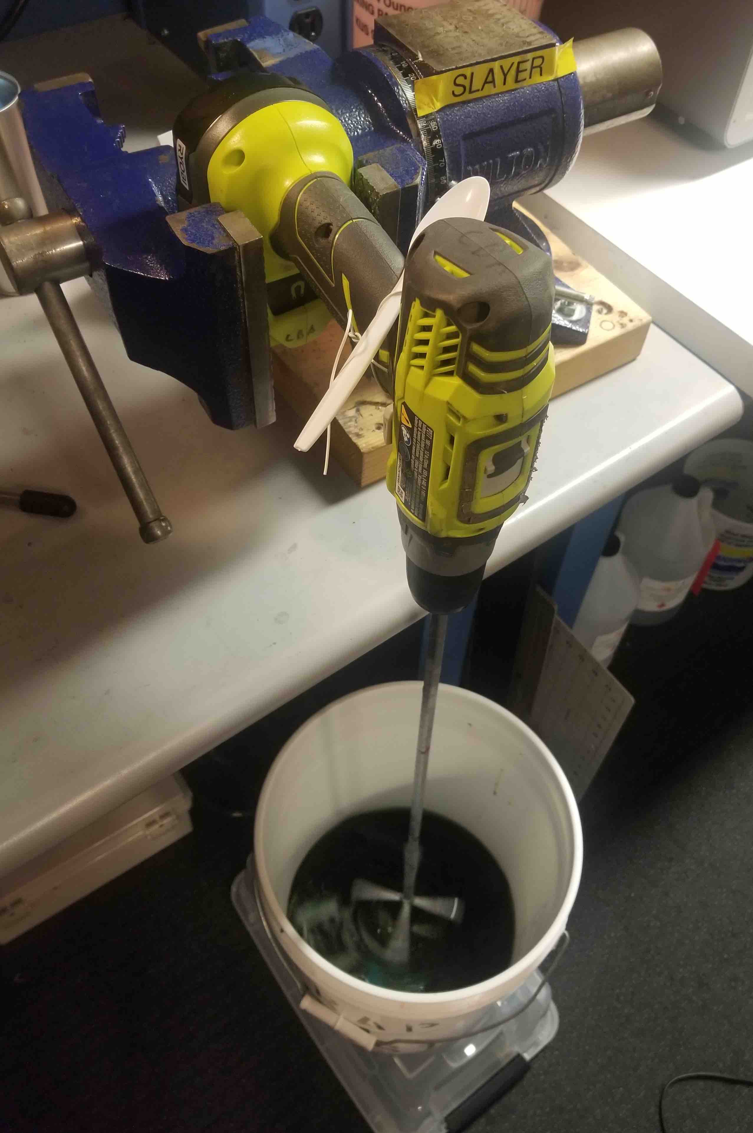
- Add the fabrics and stir them for roughly 10 minutes (we did this using a stirring tool on a drill and then using a piece of wire to keep the drill at a nice slow stir).
- While these are mixing, crush x/100 g of iron chloride (34.7 g - a little extra for crushing losses). This is easier than it sounds, they're basically small rocks. We ended up using wire cutters to get them into small chunks and the double bagging the chunks and smashing them with a mallot. Similar to the pyrrole - wear gloves
- Add a small amount of water to your iron chloride dust to make it a liquid.
- Add the iron chloride liquid to your stirring bucket and continue to stir for 45 min.
- Remove and rinse your fabrics and set them out to dry. Note that once the iron chloride and pyrrole are combiined neither are toxic anymore.
Here are the step by steps:
And, the safety data sheets for the pyrrole and iron chloride
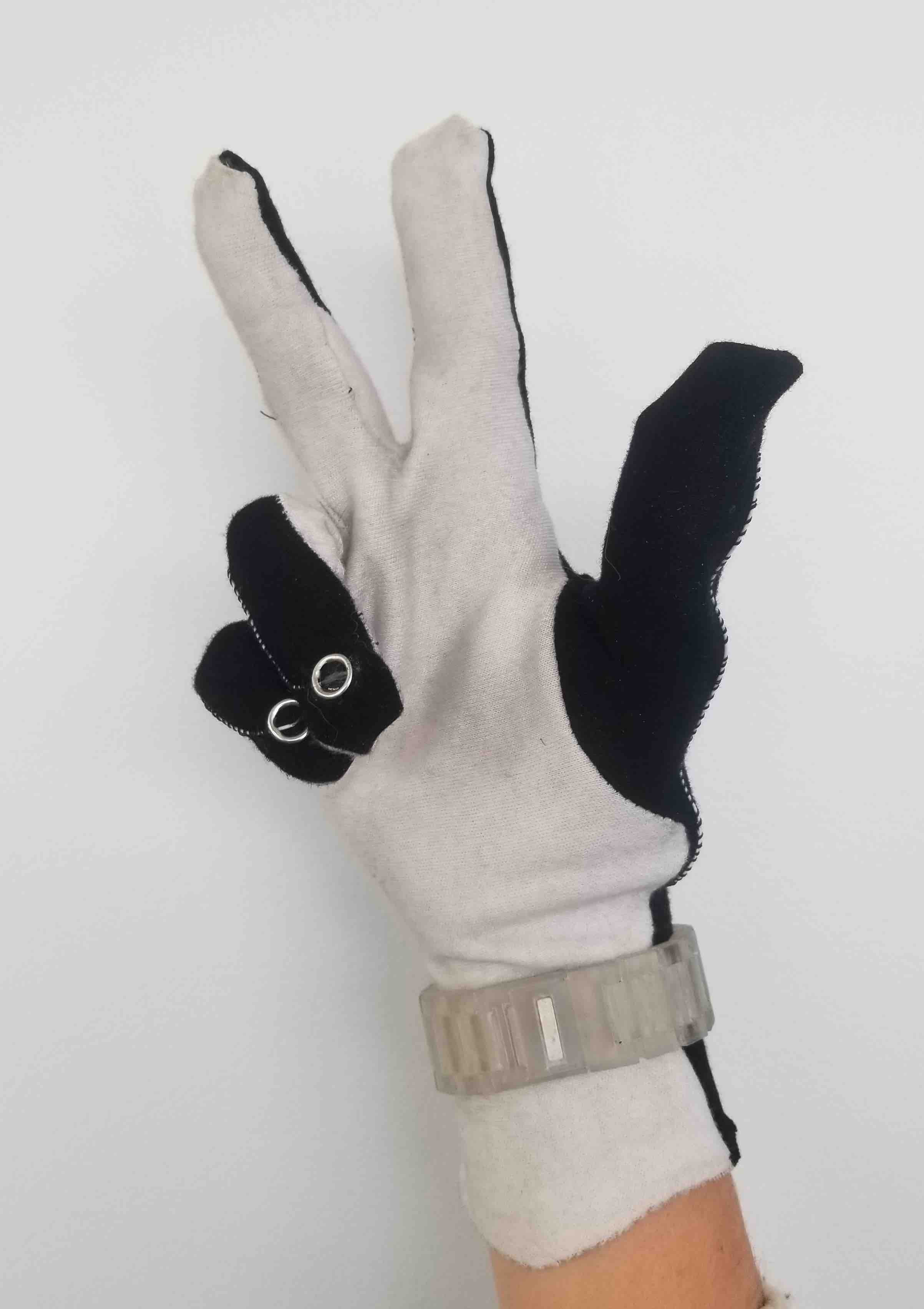
Next up, we tested the glove to make sure we were getting enough of a voltage jump that I could use it for an output to display the finger movements. I set it up so that the palm is the ground, the finger tip is a 5V input and I have the output as a voltage divider right at the bottom finger joint. Here's a clip of the voltage jump when I bend my finger (notice when I bend the voltage is higher, unbent voltage is low).
Fabrication Drafts
Making the Glove
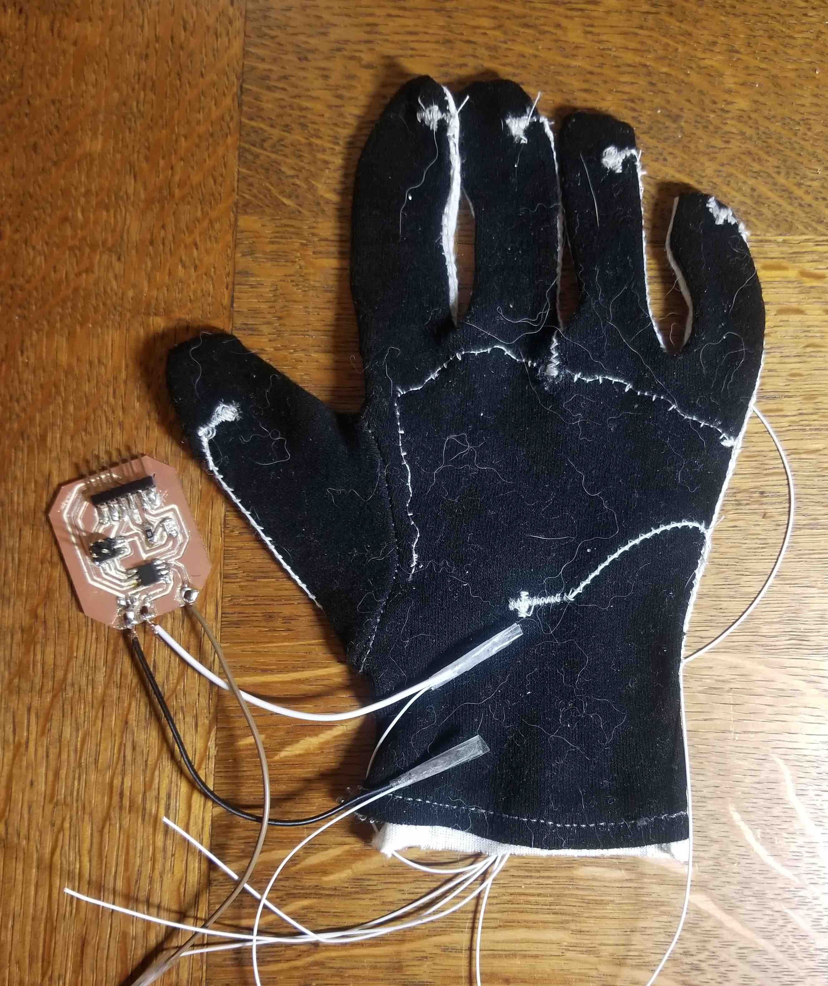
During the Input Devices week I wanted to try out my glove. I sewed in the wires and hooked up a preliminary board to check that the voltage divider was working. Here's the process I used to do this:
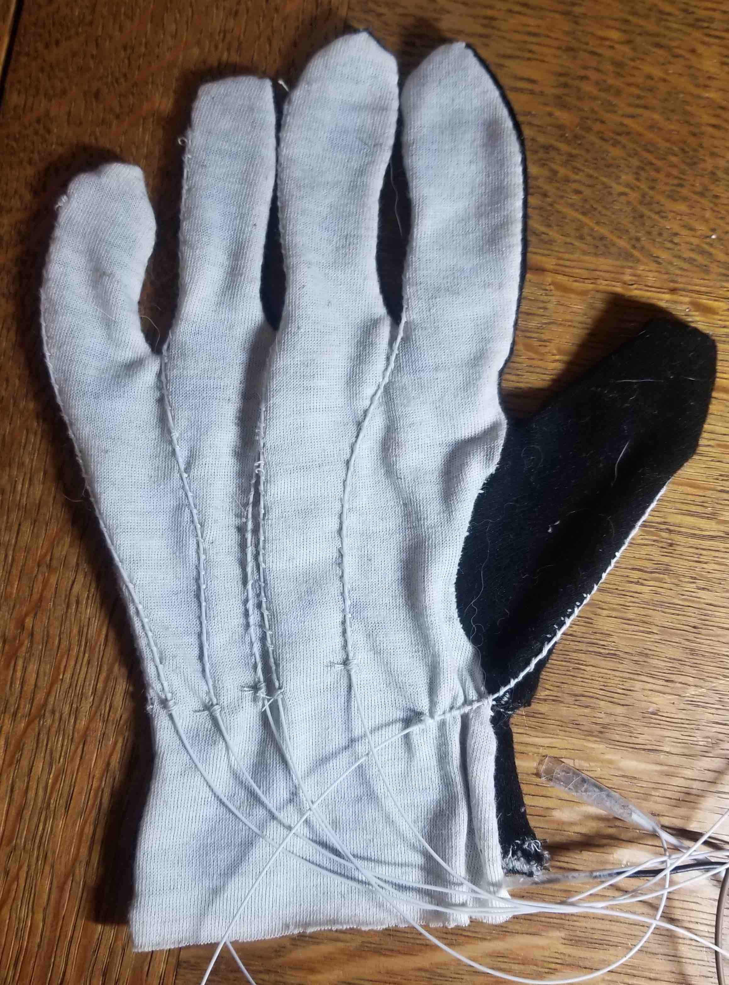
- Separate the front and back of the gloves (this is so I can use both sides as individual gloves - although it would be missing a thumb for one of them)
- Use conductive thread to sew a line that crosses the base of all fingers and the thumb.
- Use regular thread to sew the bared wire of a flexible, thin wire to the finger tips, the palm, and attached at a point along the conductive thread (this is for the analog output).
- Cut a new backing for the glove (any material here is fine).
- Sew the back and front together being careful to avoid all the loose wires.
- Sew the wires down onto the glove backing.
Here's what this looks like!
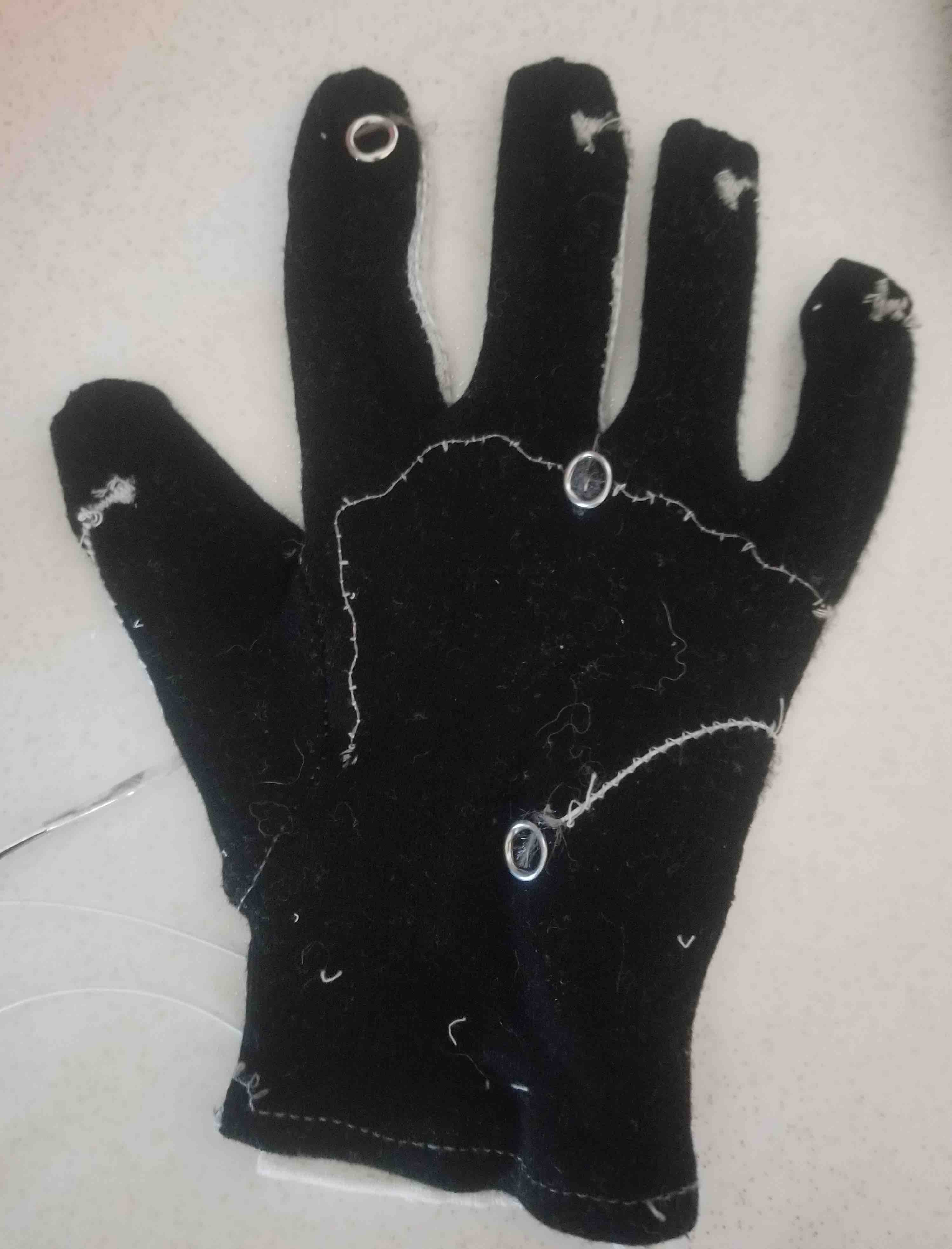
I found that the wires didn't seem to have a great connection at the nodes. To fix this, I took out the sewn pads and used snaps instead trapping the wires against the fabric really nicely. I'll be using the snaps for the final design on all of the nodes and would like to somehow snap the wires onto the board as well. Here's a look at the snaps:
Strap Design Drafts
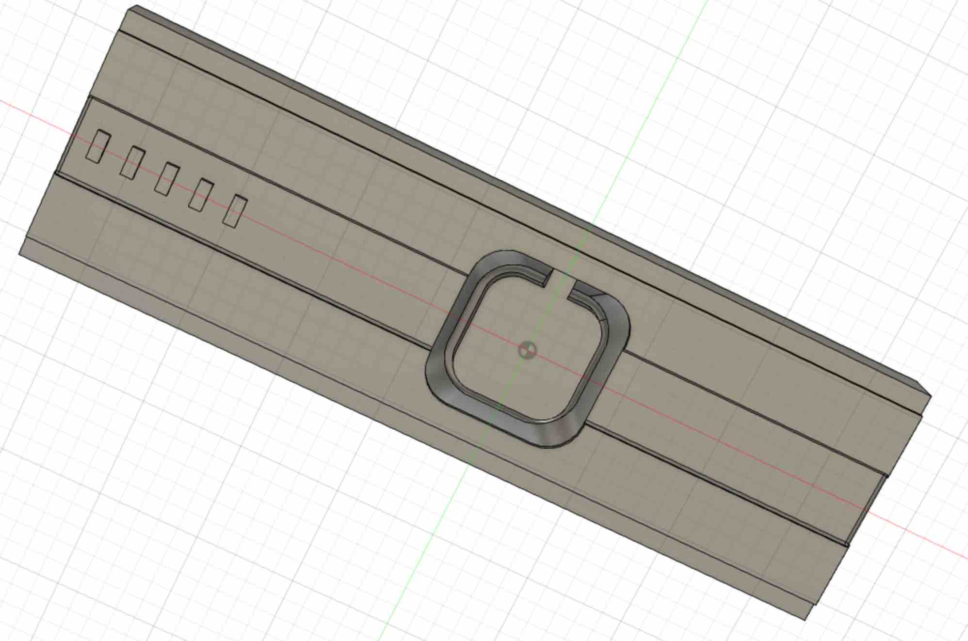
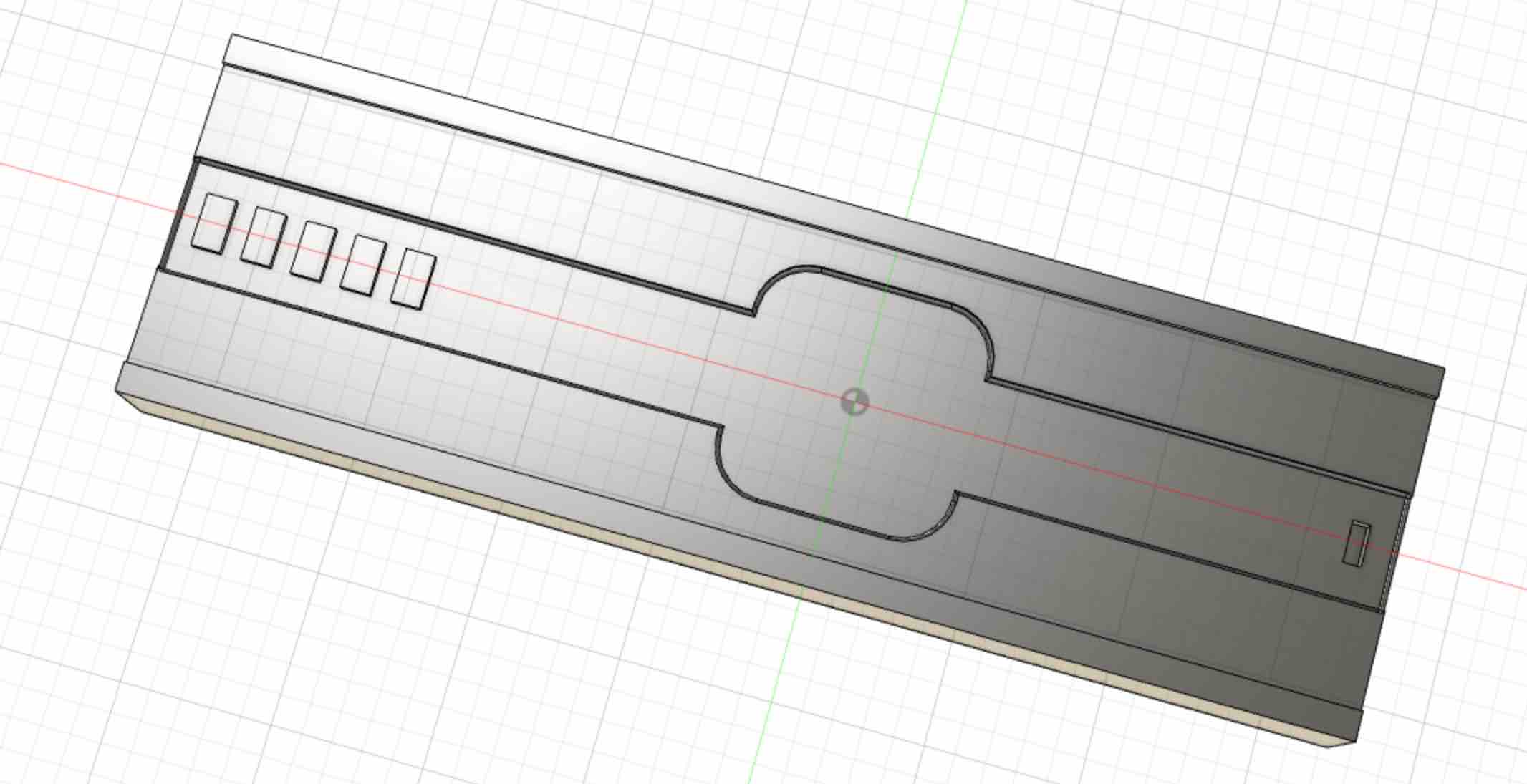
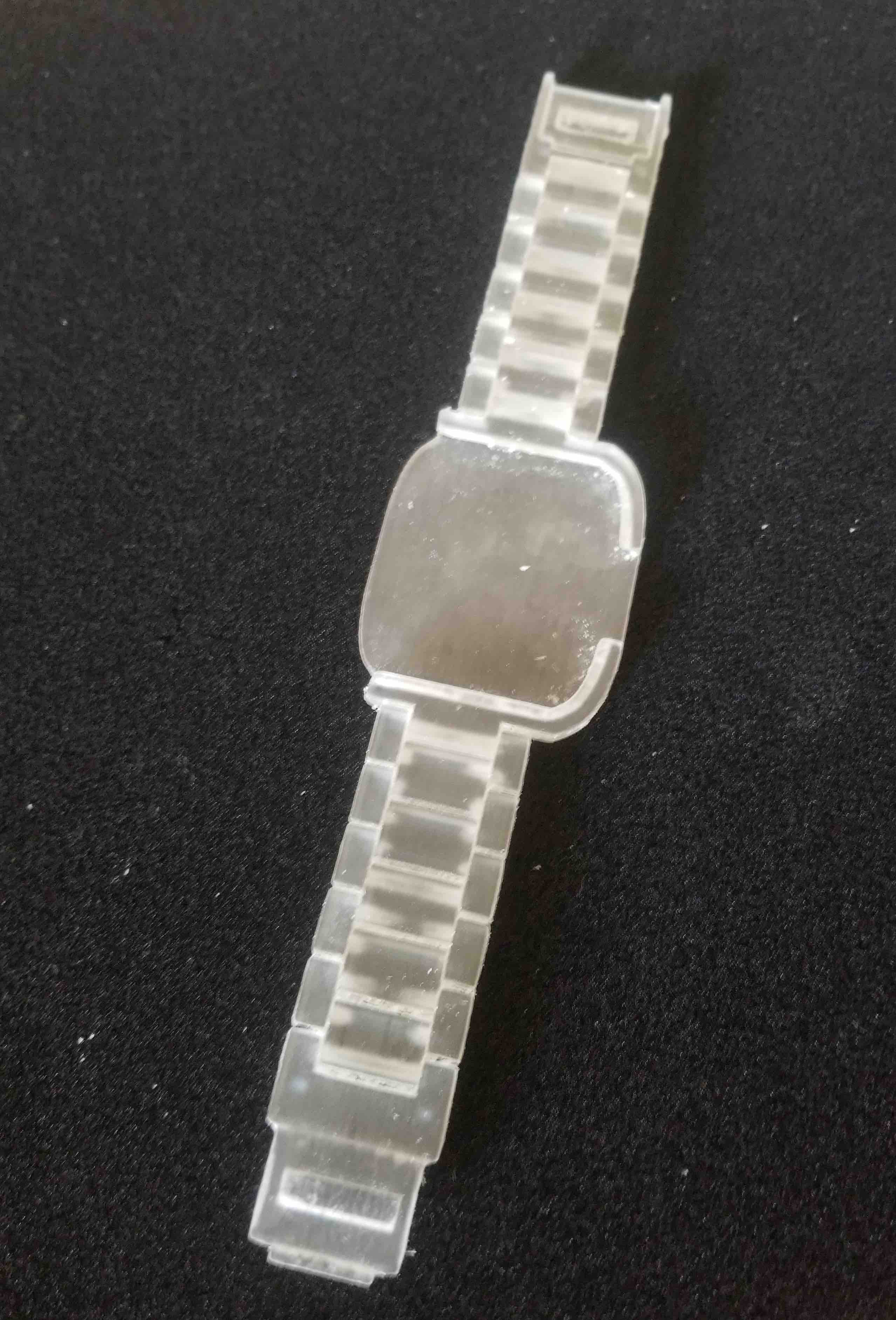
I've also started to draft sketches of the mechanical components - i.e. the strap that will hold the temperature control/display. I would like to 3D print this using print-in-place pin joints. Here is the first draft (no clasp so far).
After the molding and casting week, I thought it might be interesting to try a secondary design of my watch strap cast in Oomoo (the silicone we worked with). After looking at some of the molds that had been made with the Oomoo I did notice that the thicker the Oomoo, the more likely it was to crack. I went with a 3 mm thick strap design (parameterized of course for easy changes down the road). I had also tried doing a bit of sculpting with my planter by scraping away some of the wax to create a lip. I wanted to test out how the Oomoo would act if it had to fill in an undercut, and it worked great! So going off of this, first I designed the positive space of my strap I designed the negative of the strap to be able to be able to mill the design (so no lip), then I will then sculpt out a lip for the inside of the watch face to hold the LCD screen, as well as a 'lip' on the connector pin so it will snap into place and stay on. Here is the positive view of the design, what I will end up with in Oomoo:
Electronics Design Drafts
I've decided to use the ESP32 for my board. While I'm planning to have the power be from a micro USB for now, this can easily be changed to a battery down the road, and using the ESP32 will allow me to eventually make the glove completely wireless without too much effort. I have the power supplies for each finger as IOs on the board (I can just write them to HIGH to output power) and a single analog input for the base voltage divider. I will rotate through each power pin, reading the analog input pin at each one. This way I can tell which finger is moving depending on which power pin is active at that time. I'll be able to calibarate the voltage division for each finger so that I can know what the fully bent voltage looks like (closest to Vmax) and what the fully straight voltage looks like (Vmin). The amount of flexure will be linearly divided from Vmax to Vmin. This won't give me details like which knuckle is bending or if the fingers move from side to side but it's a good start!
Here is the ESP32 circuit schematic I've come up with so far:
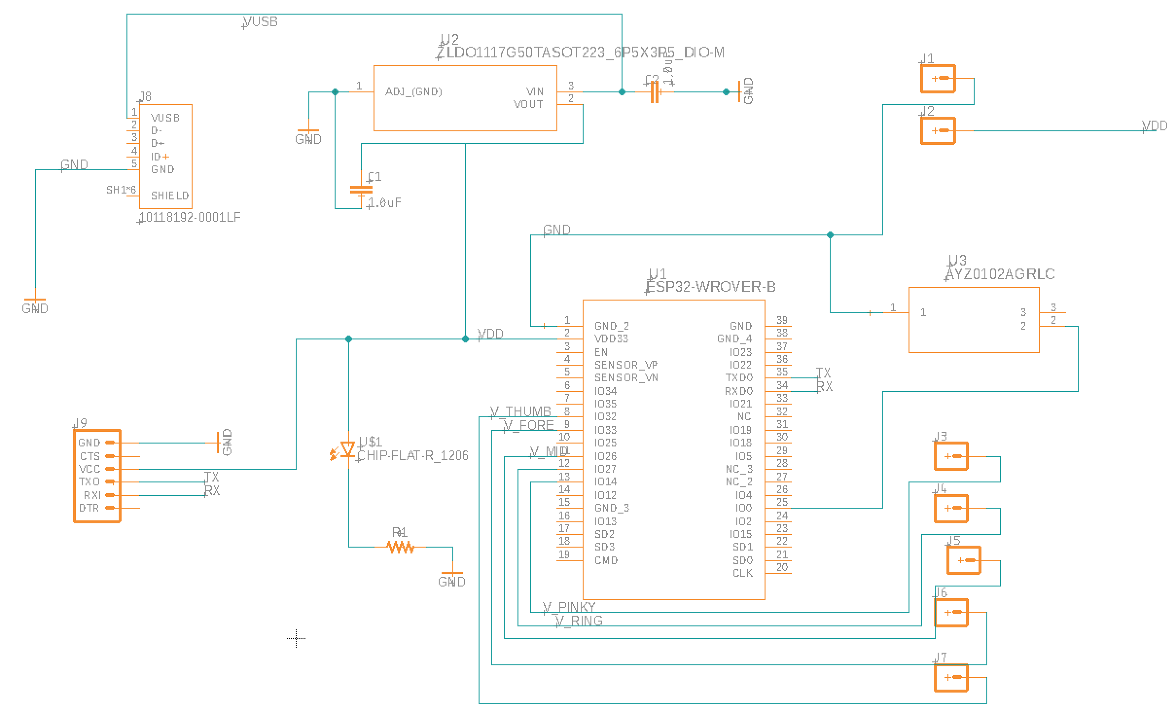
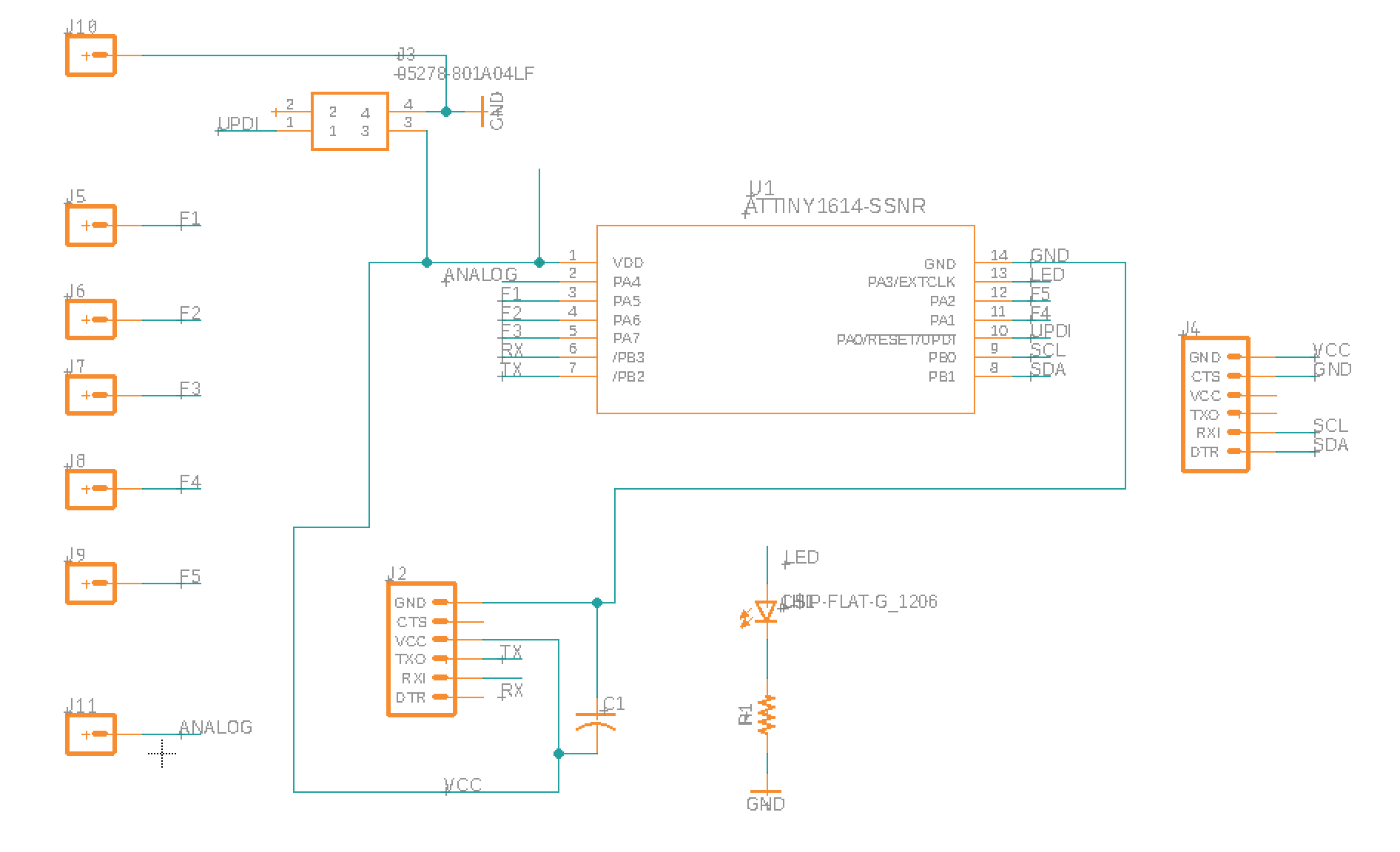
Now that I've designed the ESP32 circuit board... it turns out that the ESP32 is a bit overkill to just be used for passing analog signals. I was going to try using the RN4871 bluetooth chip, but I realized that without using battery power (which I wasn't planning on using), I would be wired regardless, so why not just up the Week 8 - Input Deices module I used with the Attiny412 to test out the glove?! Since this would be a much simpler circuit, I decided to add an 3-axis accelerometer as well to get some idea of hand movement as well as finger flexure. Here is the circuit I've designed:
Final Fabrication
The Final Glove
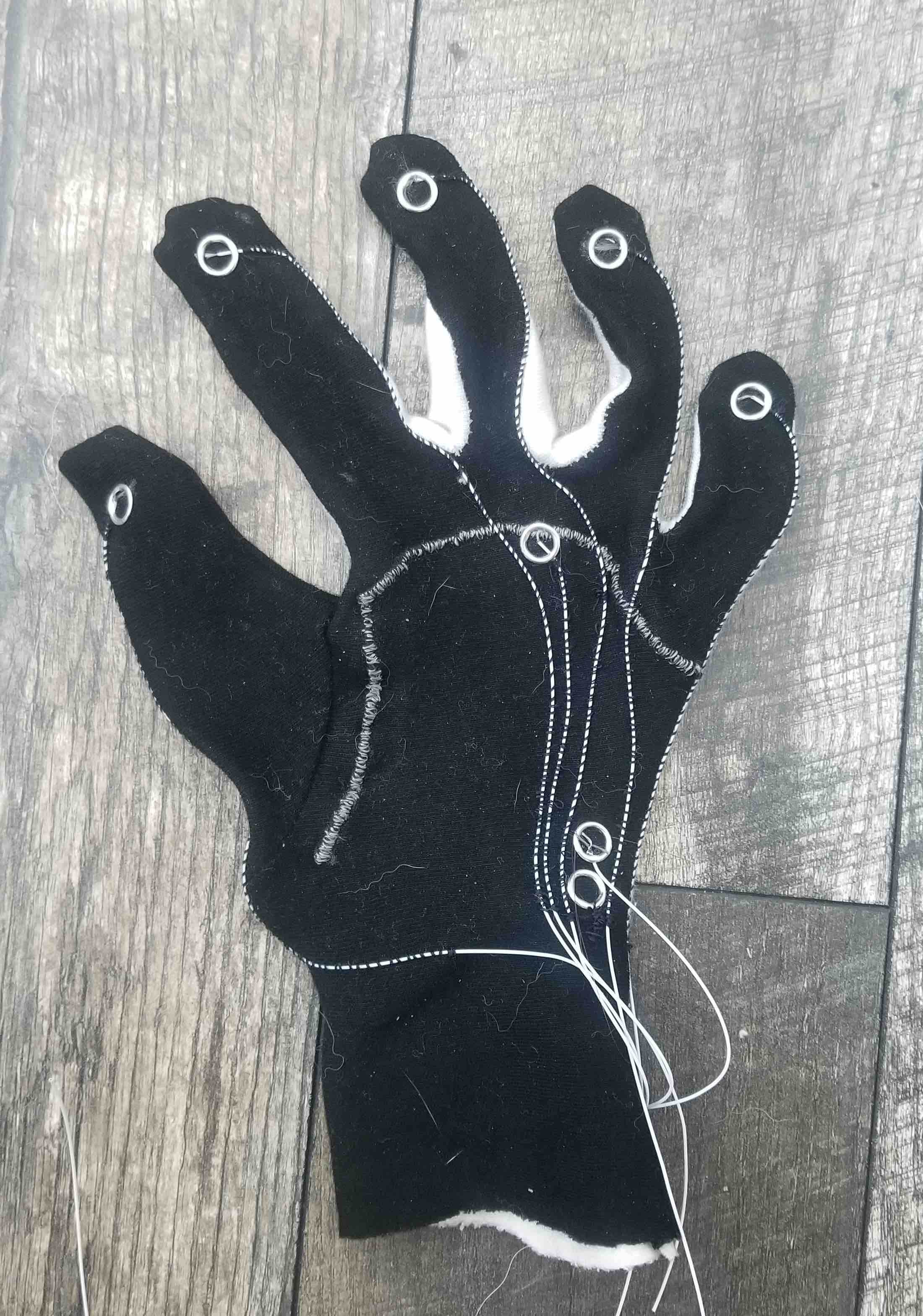
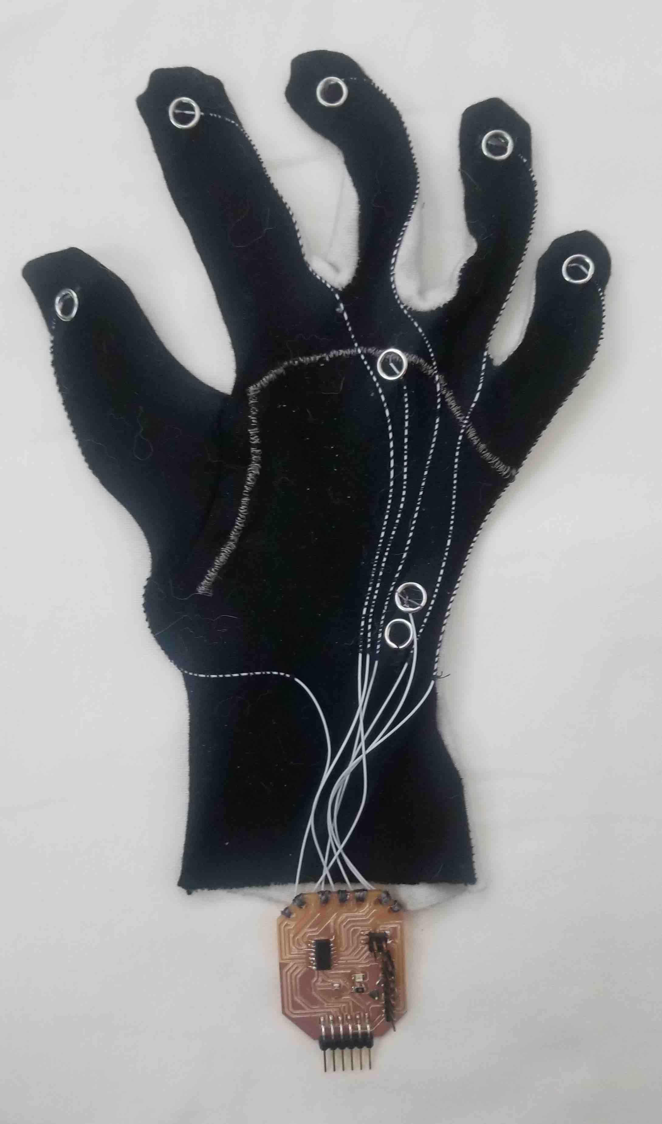
The initial glove I made was a bit small and I had to keep pulling it on while using it, which wasn't just annoying, it was also making the wires come loose. I decided to make some more functionalized fabric and to sew the glove myself so that I could make it the right size. I used the new fabric to cut the conductive side of the glove and non-functionalized material for the other side. This time I used snaps on all of the wire connections, as well as a thick zigzag stitch for the input line at the base of the fingers. This will give a better connection for my wires. I also used a small amount of super glue at each connection to ensure the wires didn't slip out (something I was noticing on the previous glove.
The Strap
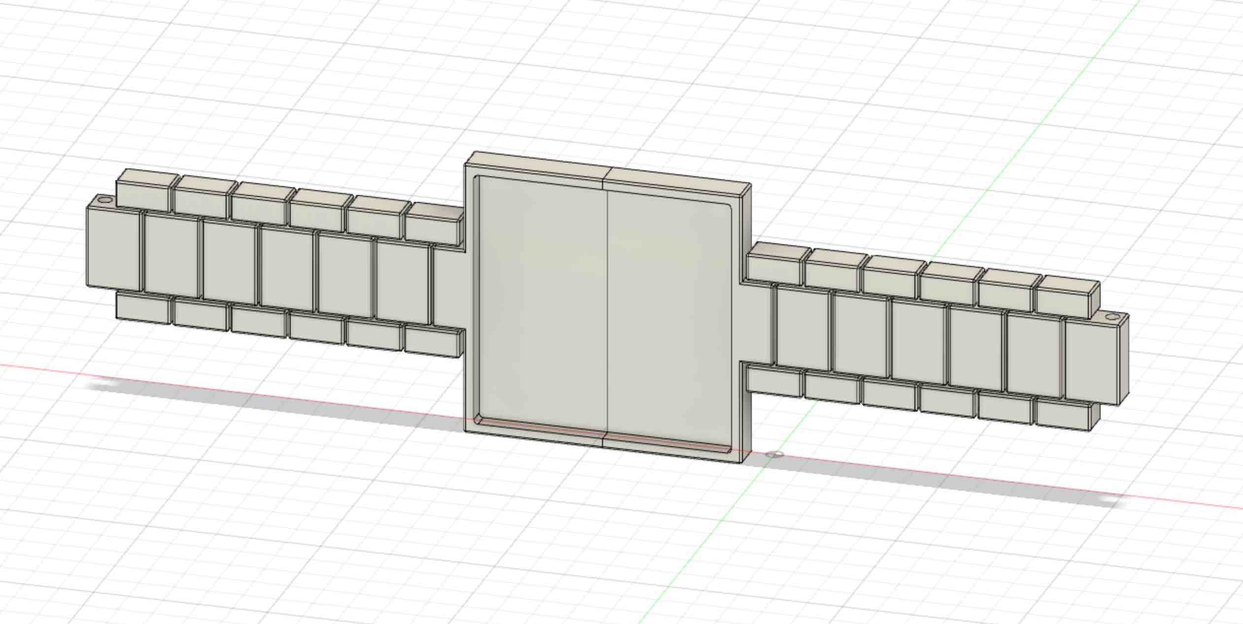
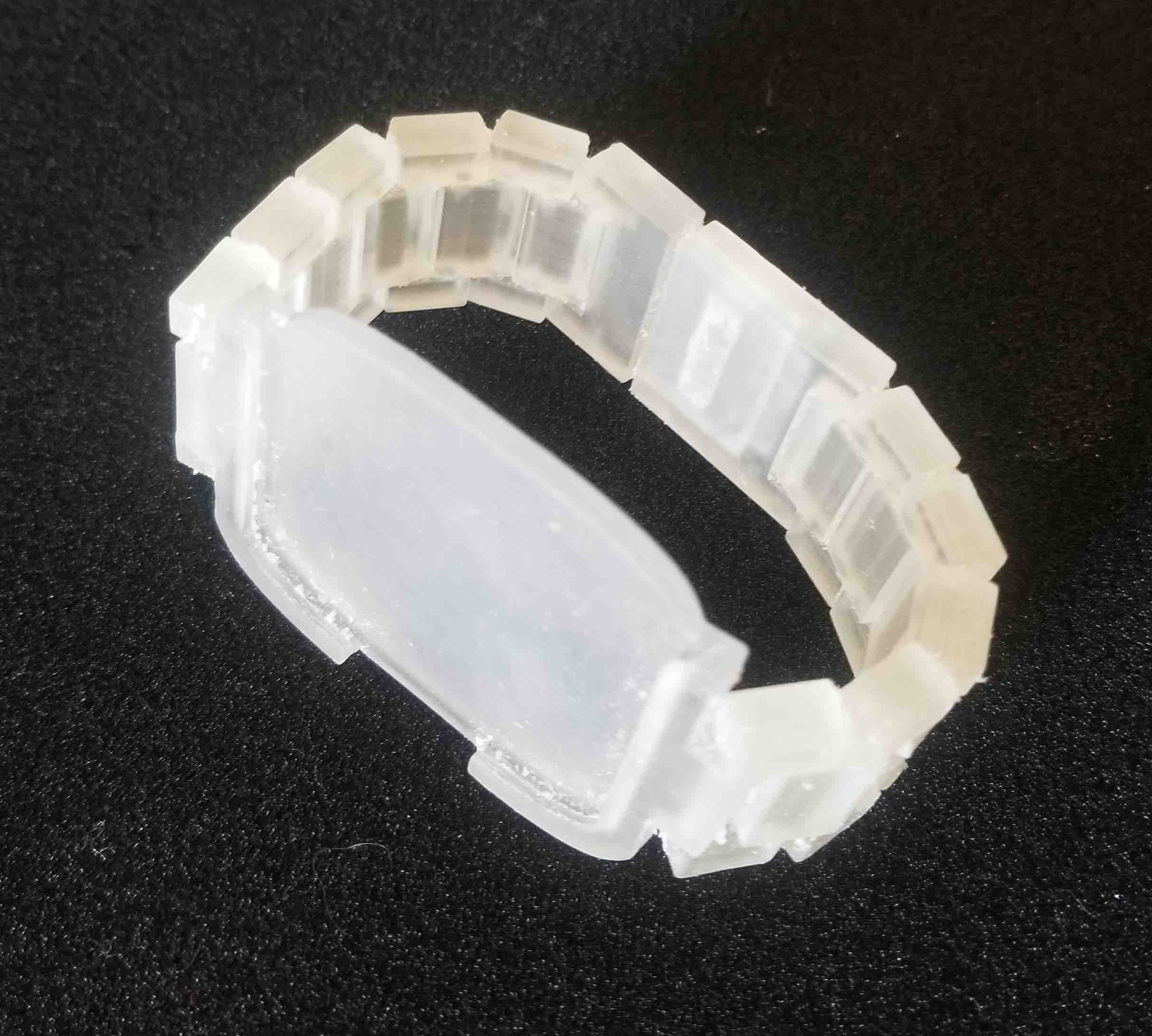
I printed the strap using the Objet 3D printer. I had characterized this printer back in Week 02 - 3D printing so I knew to use 0.3 mm gaps for all of my joints. It worked out great! I had added some slots as well in the ends of the straps so that it would snap into place when done up. After cleaning it up (delicately so as not to break the pins) in the water jet, here's the finished strap:
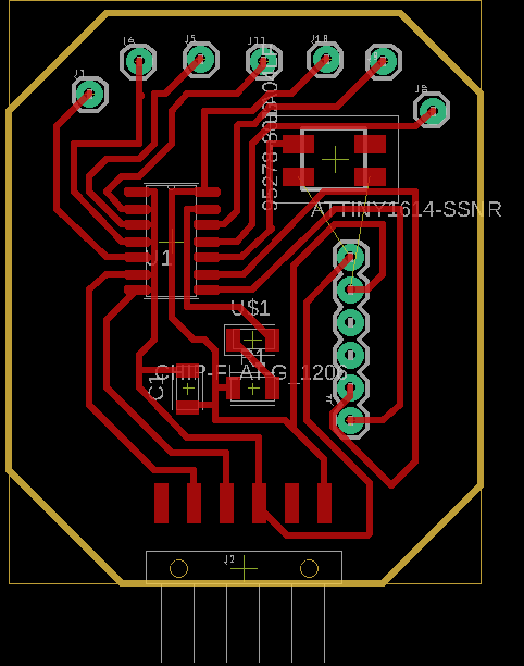
The Attiny1614 Circuit
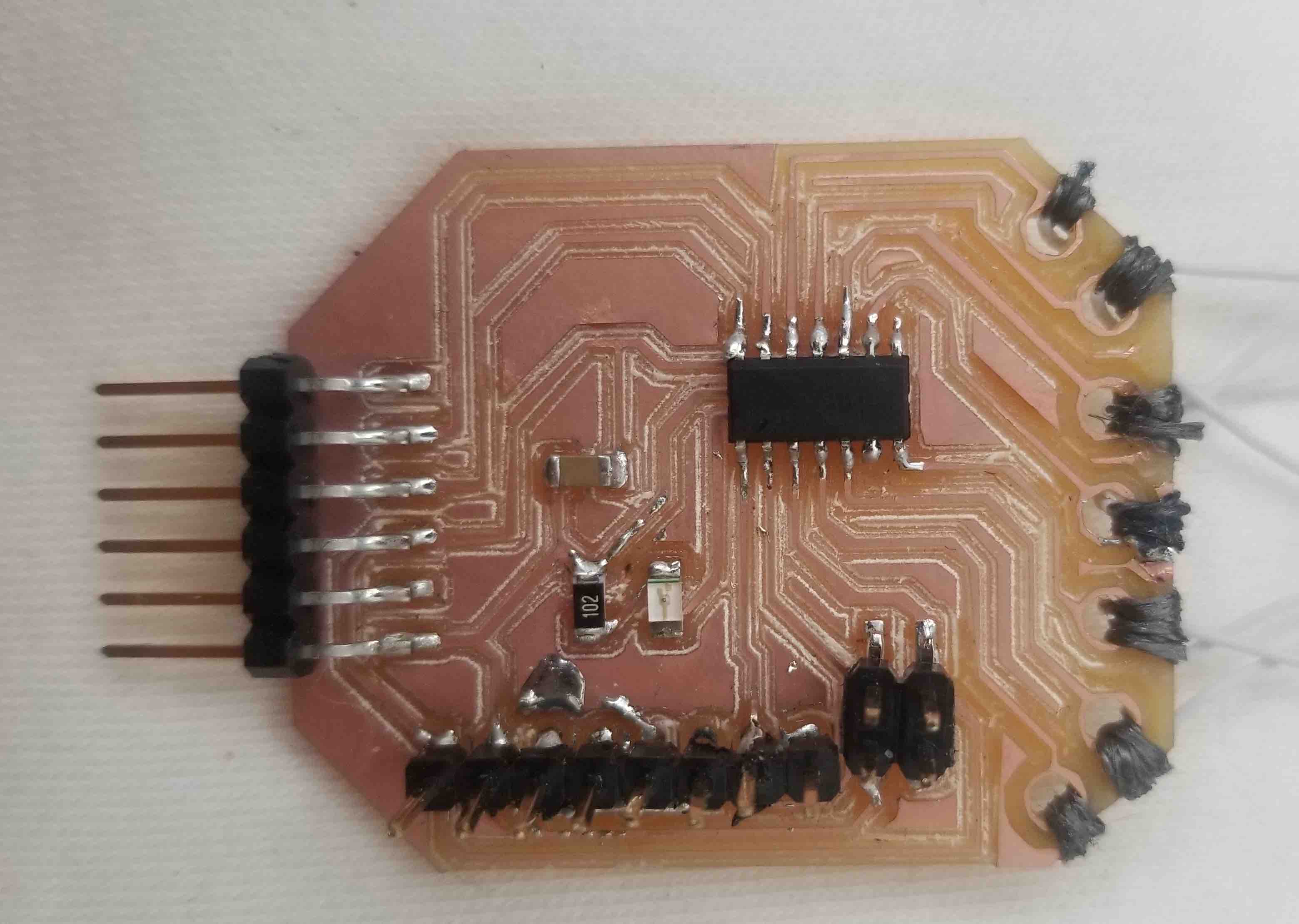
The final production of my circuit board took a few tries. I started having some issues with the engraving bit, I was finding that unless I had the depth of it exactly right it was cutting too deep and therefore making my traces far too thin. In the end I got one that worked but I think ideally I should be switching over to the 1/64th bit. Stuffing the board was also a bit tricky. I realized too late that the way I set up the holes for the accelerometer wasn't ideal and so ended up melting the plastic pin holders a few times. This may end up coming back to haunt me if I get time to implement this part of the board (although time is running short so this may not happen anyway). I used some super glue to hold the glove attachment wires in place which seems to work quite well. I've used a very flexible wire thread for this part which is helpful for moving parts. Here is the stuffed board:
The Code
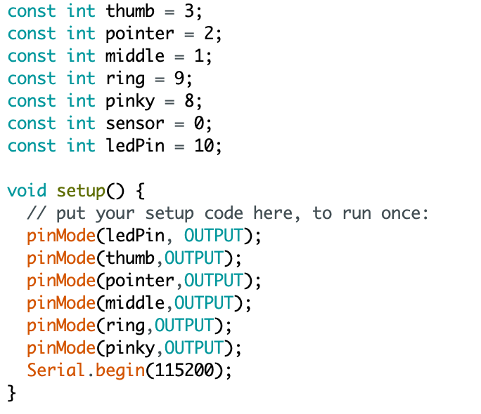
The coding should in theory be relatively simple. I just need to loop over the fingers, setting their pins to HIGH to 'activate' them delivering a voltage to each fingertip one at a time. While that pin is high, I read out the sensor voltage (the one at the base of the fingers) and this tells me the position of that finger. Here is the code I wrote up:
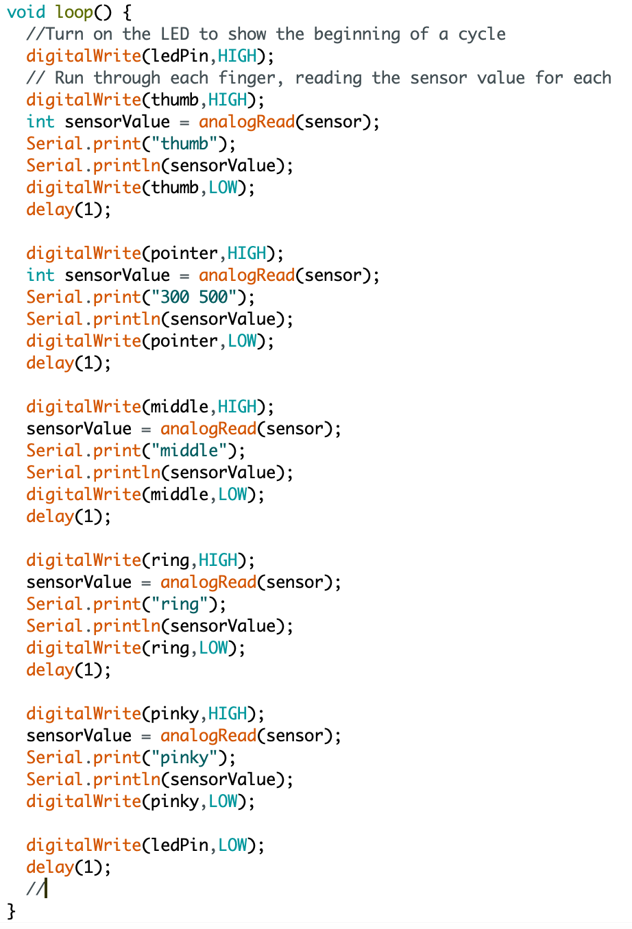
First time through, I only connected the pointer finger and the middle finger, to see what kind of signal I was getting. The code was working as expected but I needed to adjust how I was plotting the data in the serial plotter to view each finger separately.
Working in Unity I needed a script that would take in the analog input from the glove and apply it to each finger. This required me to jump between Arduino and Unity to make sure my codes could talk to each other. Here are some lessons learned:
Lessons Learned from Arduino
Lessons from Unity
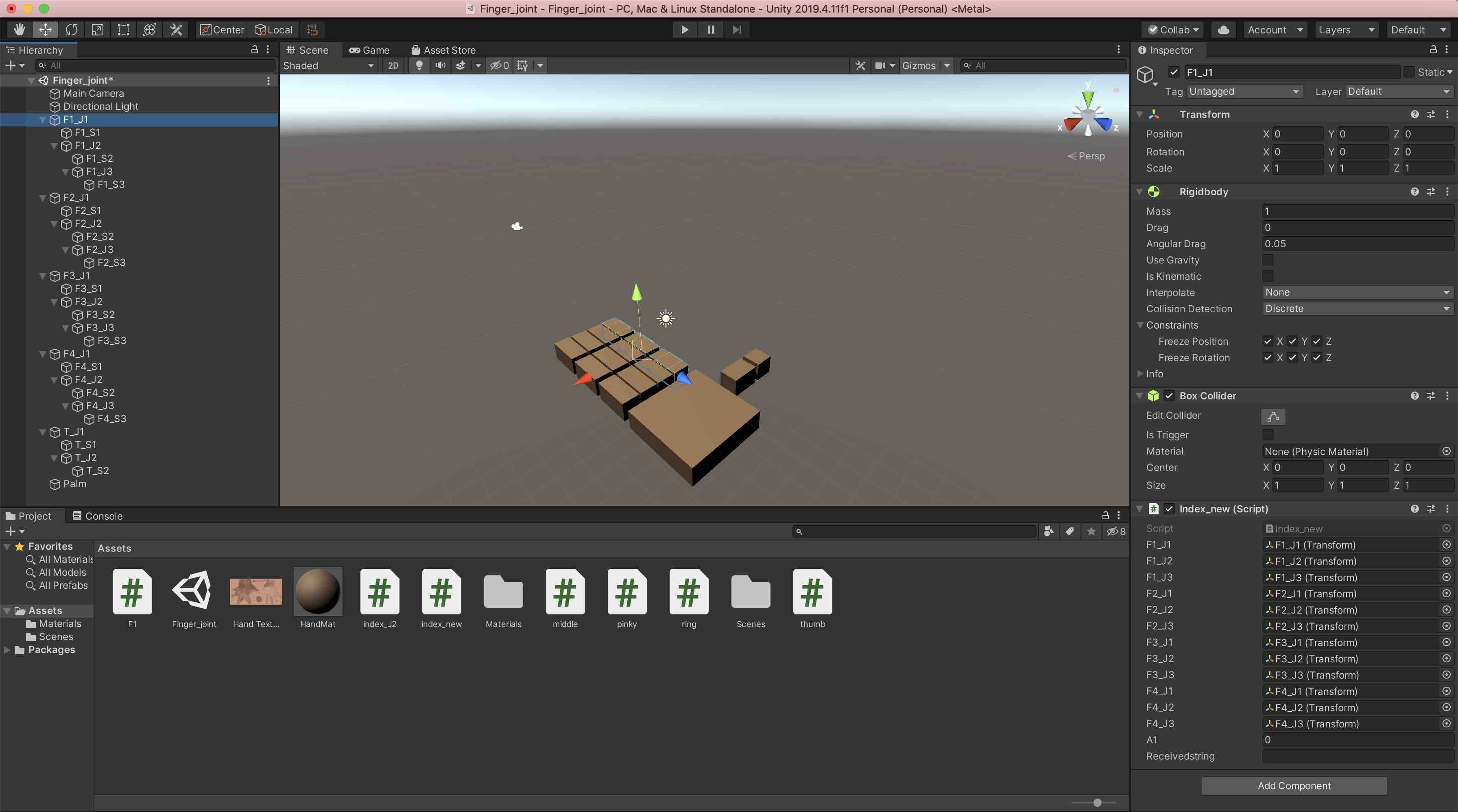
Being brand new to Unity this was a whirlwind of learning! The best advice I have is to start EXTREMELY simple. I started with a cube and tried to just make it move. From there I added some code and learned how to use scripts in Unity. I slowly added on more joints then added more fingers, and finally added the thumb. Here is the play-by-play:
And with that, hopefully my actual scripts can help to make it even more clear what it was I did. You'll find the final Arduino code and the final C# script in the Source Code section. Here is what the layout in Unity looks like:
Final Assembly
Putting it all together
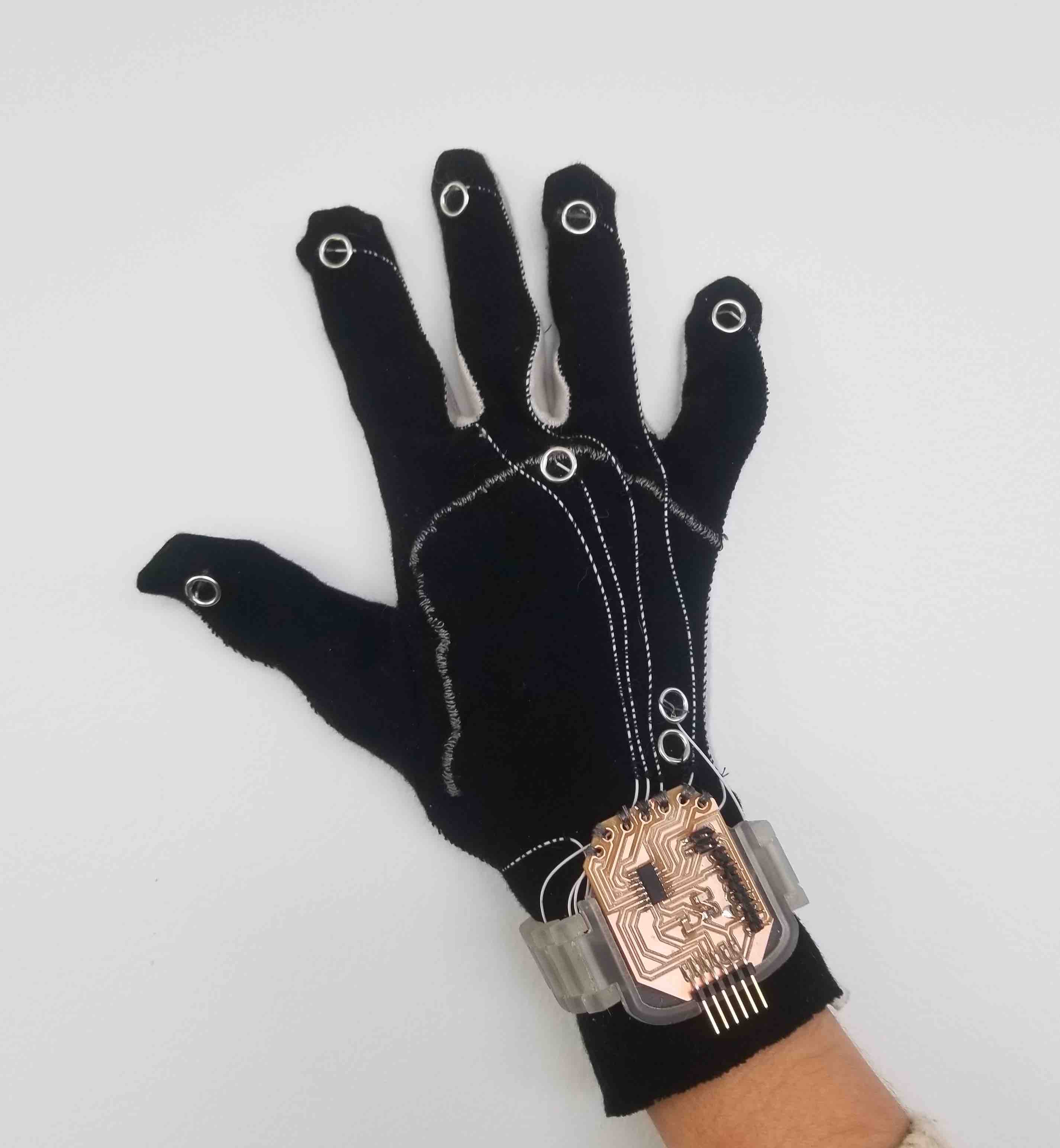
The final glove turned out pretty nicely. It fit well, good and snug, and the wires seem to be staying in place both on the glove and on the board. I left extra breathing room for the wires to move around at the board end just to be safe. Here is the glove and board connected:
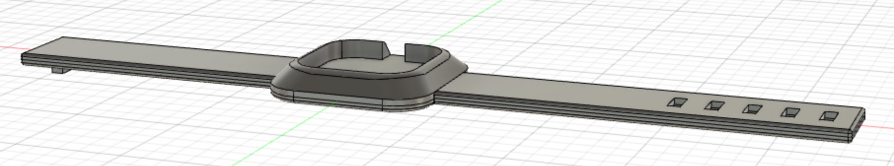
Next I added on the watch band. Pretty simple, I superglued the board to the strap and voila, finished product!
Visualizing the hand movements!
During Week 11 I learned how to use Unity and made the first finger of the glove talk to Unity and move a representative 'finger' in a simulation:
After slowly adding in each finger (and with much help from Amira Abdel-Rahman), I managed to get all of the fingers and the thumb working! A few issues --> the calibration is very challenging, particularly since it seems to change if you take on and off the glove. This meant I did all of the calibrations with my left hand (I'm right-handed) so I could keep the glove on. I got pretty adept at switching between the UPDI and TX/RX inputs with my left hand, but it wasn't perfect, hence the slightly wonky finger movements. I also didn't get to add a smoothing function, this will be the next step so the fingers don't look so jittery.
Overall, I'm very happy with how this turned out! I was so excited to see each new finger come to life and am amazed at how much I learned in such a short amount of time. With absolutely no experience with electronics, visualization engines, or circuitry, this was all brand new to me and I'm very excited that I could make something using all of my new skills.
The Final Checklist
- Stretch cotton fabric (no cost - personal inventory (~$0.50))
- Eyelet snaps (no cost - personal inventory, availabe here $4.50)
- Conductive thread (no cost - personal inventory, available here ~$1.00)
- Conductive fabric chemicals (Pyrrole - $0.70/mL, Iron Chloride - $0.41/g)
- 3D printing - PLA ($22.99 for 1kg, ~$1.50)
- PCB board (CBA inventory - $1.40)
- Attiny1614 (CBA inventory (digikey: ATTINY1614-SSFRCT-ND) - $0.67)
- LED ($0.33, digikey: 160-1167-1-ND), 1k resistor ($0.10, digikey: 311-1.00KFRCT-ND), 0.1 uF capacitor ($0.35, digikey: 399-4674-1-ND) 1x6 connector ($0.48, digikey: ADT-AMP1251106S4BS165A1), 2x2 connector ($0.74, digikey: 609-5160-1-ND), 1x8 connector (home lab inventory, total: $2.39)
- Serial adapter (home lab inventory - $21.25)
- Arduino programming software (free)
- Unity game engine (student edition - free)
- Total cost (assuming paying for all inventory): $55.84 ($34.59 if you already have a serial communication device)
- Sewing
- Conductive fabric production
- Parametric design (strap)
- 3D printing (strap)
- Circuit board design
- Milling (Circuit board)
- Soldering
- Input - analog voltage input communication
- Interface and application programming
Source Code