Goal#
- Measure something: add a sensor to a microcontroller board that you have designed and read it
Result:#
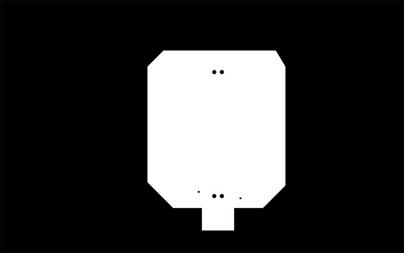
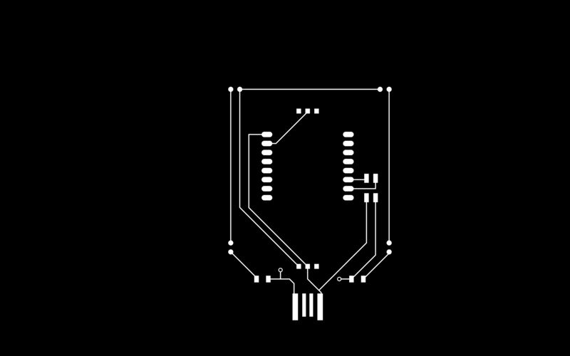
 Here are my design files at the end of this week but DO NOT bother milling them, I later realized they were wrong
This was a short work week for me for health reasons. I tried to make my time as useful as possible towards my final project. I also started designing a board that I could use for both my input and output devices week. The board has a mount for the ESP32-CAM Ai Thinker module and a ring light of Infrared LEDs, as well as switches for turning the LEDs on/off and for putting the ESP32 into/out of flashing mode.
I knew my project would involve a camera so I picked the ESP32-CAM as my input device for this week. At first, programming was a hassle. The ESP32-CAM does not have USB, so you have to program it using Serial. I spent a whole day just trying to get my USB to Serial converter working, including milling and stuffing a whole new one. Details here, from I tried to get help.
The next day, Zach gave me a USB to Serial cable, thank goodness! I was still having trouble getting Arduino to see the ESP32-CAM under its ports though. After an hour of troubleshooting, I asked for a different cable and that did the trick. During troubleshooting, I did learn that I was missing needed drivers from this blog post. And here's the link to the driver.
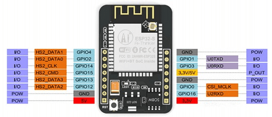
For getting started programming the ESP32-CAM, I extensively refered to Random Nerd tutorials, especially their pinout reference for the Ai Thinker module which is what we have in CBA. I also used the Arduino core for ESP32 by Expressif found here.
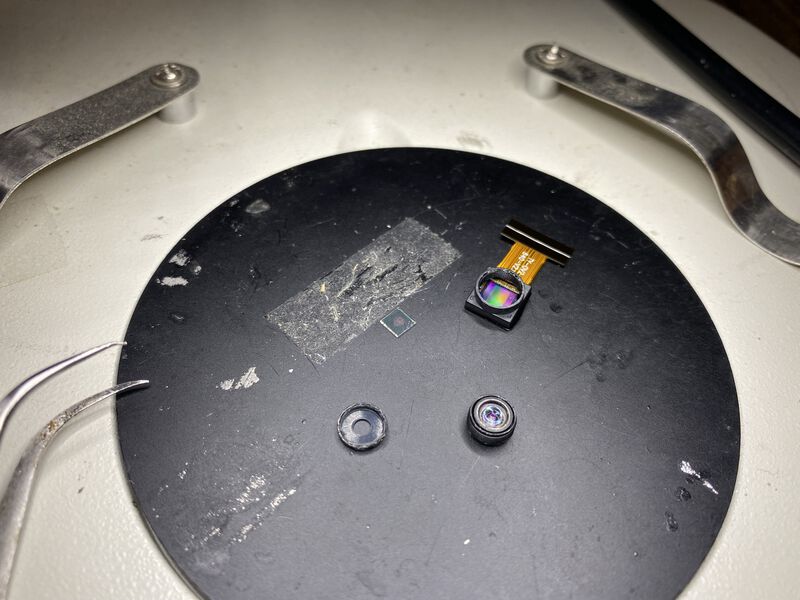
I wanted to mill on this day but the milling machine was occupied. I still had things I could do while in the shop though! Because I want to use Infrared for the object tracking in my final project, I had to turn the ESP32-CAM into an infrared camera. I found some posts about removing the IR filter in the cam, like this one, and got ready for surgery.
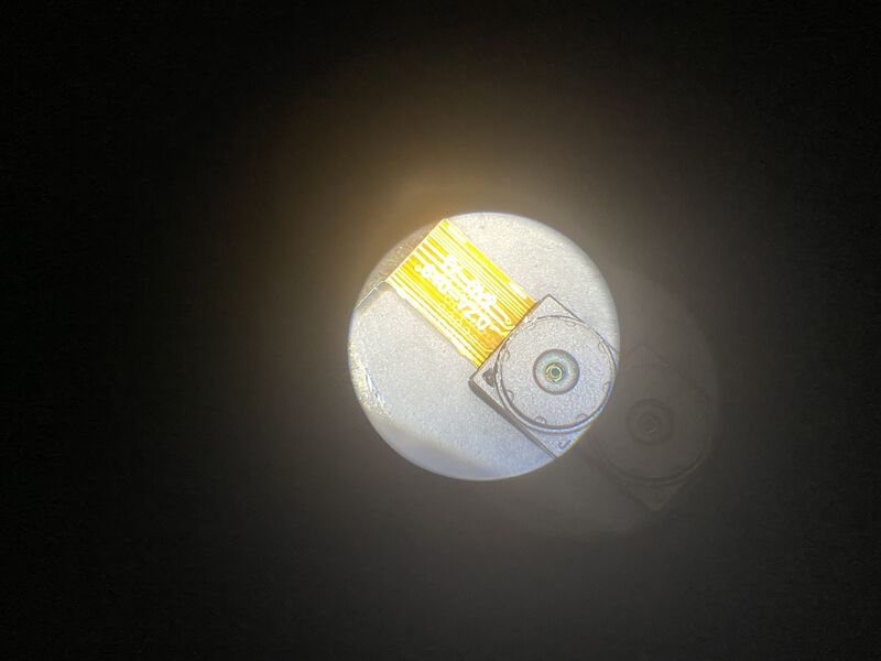
Strangely, my camera internals looked different from the ones in the blog posts. I didn't have a red circle filter, but I did have a green square thing that I assumed was the IR filter and took that out. Thanks again to Zach who was more fearless than me in shoving the razor blade into the camera.
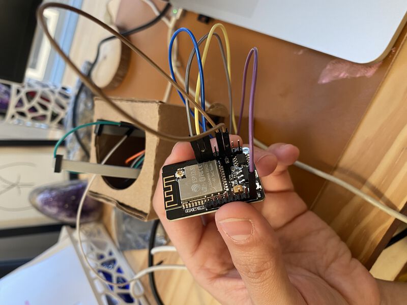
After getting back home, I set up my ESP32-CAM for programming. I learned that you have to connect GPIO0 to GND to put it into flashing mode, which let's you upload programs. Zach taught me that, in the USB to serial cable, the ref cable is 5V and the black cable is GND. The orange and yellow cables are Rx and Tx but unclear which was which. After testing both, I found out that orange is Rx and yellow is Tx. I also learned that you need to connect the Rx cable to the Tx pin and the Tx cable to the Rx pin. After figuring it all out, I used this photo for reference throughout.
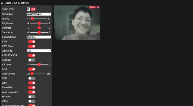
I uploaded the example camera server code that comes with the Arduino core for ESP32. I did have to change the code a bit to set the type of ESP32 module I'm using (Ai Thinker) and set my network info. At first, I struggled to connect to MIT's network, but then Cedric gave me the great idea to just hotspot off my phone and connect to that. After taking the module out of flashing mode, I opened the Serial terminal in Arduino and hit the physical reset button on the module. I saw the module connect to the wifi and start a server where I could see the camera stream.
I tried to mill two more times but every time I came by the shop there was already 2-3 people in line to mill. When I finally got a slot, the most frustrating thing happened. When my board was 99% milled, it jerked out of its place and the endmill cut a few traces.
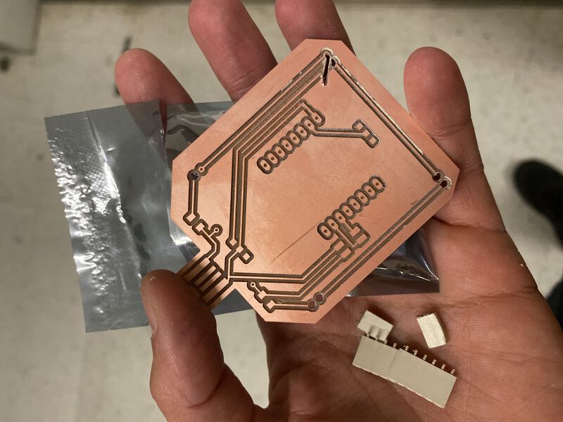
I guess I didn't have enough tape behind the board, or the tape was weakly holding to the sacrificial layer because of leftover PCB dust. Well, it turned out my design was a little wrong anyway. I used the footprint for the ESP32-CAM Ai Thinker module, but decided I didn't want to solder it directly. I also decided I wasn't going to solder the LEDs through my board, just mount them on top. So I took this milling fail as a sign to go home, rest, and try again another day after a redesign.