Goal#
redraw an echo hello-world board, add (at least) a button and LED (with current-limiting resistor) check the design rules, make it, and test that it can communicate
Result#

I learned that the recitations are not for complete beginners so I decided to try to learn Eagle on my own so I had some knowledge to go off of when I got to recitation.
First off, I download the parts library and design rules from this link. I found the FabAcademy's tutorial on Eagle but the instructions are a little mismatched. This is what I did to add the parts library:
- Clik on the Library menu at the top
- Click on Open Library Manager
- Go to "In Use" tab
- Click on "Browse" and find the fab.lbr file
- Select it and click "use" near the bottom
I'm a little confused about how to look at something like the board file and know what the components are. Googling things like IC1 D11C or IC2 3.3V is not helpful. But I know at least one of the parts is the atsamd11c so I'm gonna try to add that to the schematic. I opened up the "Add Parts" menu and tried searching for atsamd11c but nothing came up. I manually searched for it under the fab library.
I can also tell from the design that there's a 4-pin header so I looked for that. It's annoying that I can't use the Search function because, for example, I'll search "header" and nothing comes up under the fab library. But if I look manually I did find CONN_02X2-PINHEAD-SMD. Next I tried to figure out what C1 1uF could be.
UPDATE: I learned from this YouTube video that you can search in Eagle like *this* to say the term can have anything before or after!
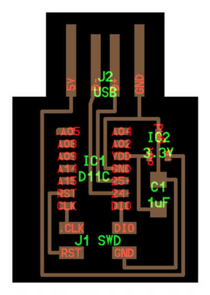
I feel like I'm missing a very basic thing because these labels mean nothing to me and googling them isn't shedding any light. So I looked at the components photo
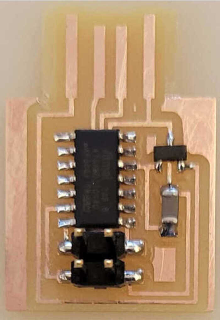
And I thought that part looked like a capacitor based on when we soldered our programmer boards in Week 2. I looked in the parts library for a capacitor that looked most like the one in the photo. For the last part, I really had no idea even when looking at the photo of the components. I know I soldered one of these parts too but I didn't remember what it was called. I had the idea to check Neil's HDL code for clues and was delighted to find IC2 = regulator_SOT23('IC2\n3.3V'). A regulator! I searched for that. Again I just picked the regulator that had the same shape as the one on the board design.
At this point I was wondering if I needed to add the USB part as well. I noticed it's labelled on the board design so sure, let's add it, and I see something in the fab library that has USBA (from Neil's code I noticed it said USB_A) and looks to match.
Ok so at this point I think I have the base parts, and need to add the LED, button, and necessary resistors. From reading the FabAcademy guide I figure I should also add VCC and Ground as well.
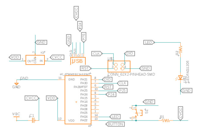
Now I need to connect everything! The FabAcademy guide suggested I use "nets". Connecting VCC and GND to the atsamd11c seemed straightforward enough, although I had trouble moving parts around. I did also remember from class that we should put a capacitor between VCC and the microcontroller. Then I thought connecting everything else to VCC and GND would be the next easiest step. I started with the button and thought to also connect it to one of the analog pins on the microcontroller which I could tell by reading the datasheet. I wasn't sure this was the right thing it just "felt" right like the button felt like it's an analog not digital thing so... yeah. Around this point I learned about labeling and naming the nets so that you don't have to draw every single one getting all crossed over each other. For future reference, when you create a net the first time you use Label. When later you want to connect something else to that net you use Name.
I went around the components trying to connect things as best as I could remember from clues in class. For example, I remembered that the LED should have a resistor. I figured the LED should also go to one of the analog pins on the microcontroller. I connected the USB following mostly Neil's board design, though I started to wonder if I had the wrong USB part because mine had VBUS and the other pins were in a different order. None of the other USB parts in the fab library seemed any better though so I left it for now. I could see also from Neil's design how the regulator was connected to the microcontroller at VDD and how it connected to VCC and GND. I got a little confused on how to connect the 2x2 header, tried looking for its datasheet, then realized that the pins on the connector don't have any particular purpose because it's just a connector not something like a microcontroller. I tried to find out which was the CLK pin on the microncontroller by looking at the datasheet but didn't find that info. Same for DIO. I created those nets coming out of the header and moved on. Will ask a TA later. This is what my schematics looked like before recitation:
Questions I have for TAs/peers:
- How do can I learn to recognize components from Neil's board designs?
- How do I know which pins on the microcontroller are DIO and CLK?
- Do I need a polarized or unpolarized capacitor?
- Is my assumption that the button and the LED should connect to the analog pins on the microcontroller? What sorts of things would need to connect to digital?
- Is my USB component OK even though it's wrong order of pins and has VBUS rather than 5V?
- Can you double-check my Eagle design rules?
- Why in Neil's design is VDD connected to the regulator AND directly to the capacitor?
Answers from Jake:
- Neil assumes people just know how to recognize parts. Do your best.
- It's somewhere in the 981 pages of the datasheet.
- Unpolarized
- It doesn't matter (plus some stuff I barely understand about turning a digital pin into an analog pin)
- Yes, the schematics doesn't necessarily match up with the footprint
- Maybe during office hours
- The regulator just converts 5V to 3.3V. The capacitor serves as a bypass capacitor.
On Friday morning I worked on the routing. Jake's video was really helpful, especialy the part about connecting everything to GND with vias. My biggest struggle was just moving parts around until I could make the traces without crossing over each other. I also made the mistake of saving my schematics and PCB with different names (echoSchematics and echoPCB) and I think that disconnected the two things and they went out of sync. But I was able to manually reconnect and fix. I ran the DRC and saw some "Restrict" errors related to the USB, but Jake said I could ignore those.
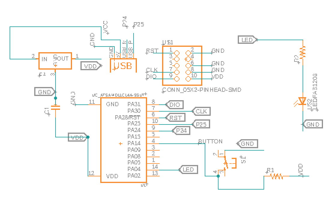
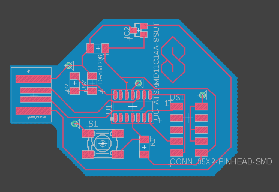
It's now Monday and I've been making some small updates. First, I changed my schematic so that the only place the VCC net from the USB went as the input side of the regulator. The button then got changed to connect to the output of the regulator. I also swapped out my USB component because it had a "keepout" area that was intefering with my copper pour. Jake helped me figure that out. Finally, I rearranged my parts so I had space to add a design for decoration purposes. Here's my board now, and my final schematics:
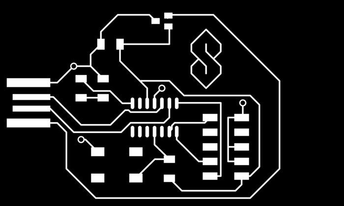
Zach helped me edit my vias in GIMP so that they would be milled correctly (I later learned to how to export the images directly from Eagle thanks to Reina! Steps at the bottom). The outer circle of the via should be included with the trace image. The inner part of the via should be in its own file and milled on the outline settings. He also explained how to actually wire up the vias:
- Get some wire and strip it to expose the copper
- Feed it through the via
- Solder the top part
- Flatten it against the bottom part
- Slap some flux on it
- Tin the tip of the soldering iron
- Hold it against the wire and the bottom copper for much longer than usual, 5-15 seconds, while feeding more solder
I biked over to the lab to try to mill and it was PACKED. I got there at like 3:30 and didn't start to mill until 7. In the meanwhile, I tried to help answer my peers' questions.
Another thing that happened was someone came in and told us not to use the 4-pin headers because other's had trouble programming. They said to use the 10-pin header. I ended up changing my design but I kind of regret it. People give a lot of good advice to others from experience ("set DPI to 2000 in mods", "set your tool a little smaller if needed", etc.) but I shouldn't trust every single piece of advice. Others eventually were able to program their boards and the issue had nothing to do with the 4-pin header. Here's my final schematics:
Actually, we're still not sure what the issue was. People on OSX kept getting Error: invalid response received when trying to flash the bootloader onto their boards using edbg. Others got around it by using the Linux machine in 043. But I didn't want to take up the one computer that was connected to the milling machine when everyone was frantically trying to get their board done.
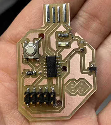
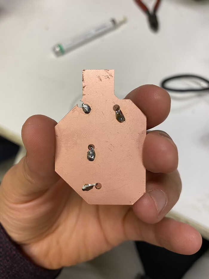
On Tuesday I came in to stuff my board. I used Zach's trick to wire up the vias and was surprised that it turned out good! I accidentally made my vias too big, I think when I exported the image I used the outside instead of the inside dimensions, but it didn't cut any traces so all was good.
Next I moved on to programming. I started with this tutorial, which seemed super helpful, but edbg wasn't working on my machine and I didn't want to take up space on the Linux machine in 043. I did also take this opportunity to try out the multimeter and make sure my connections were good.
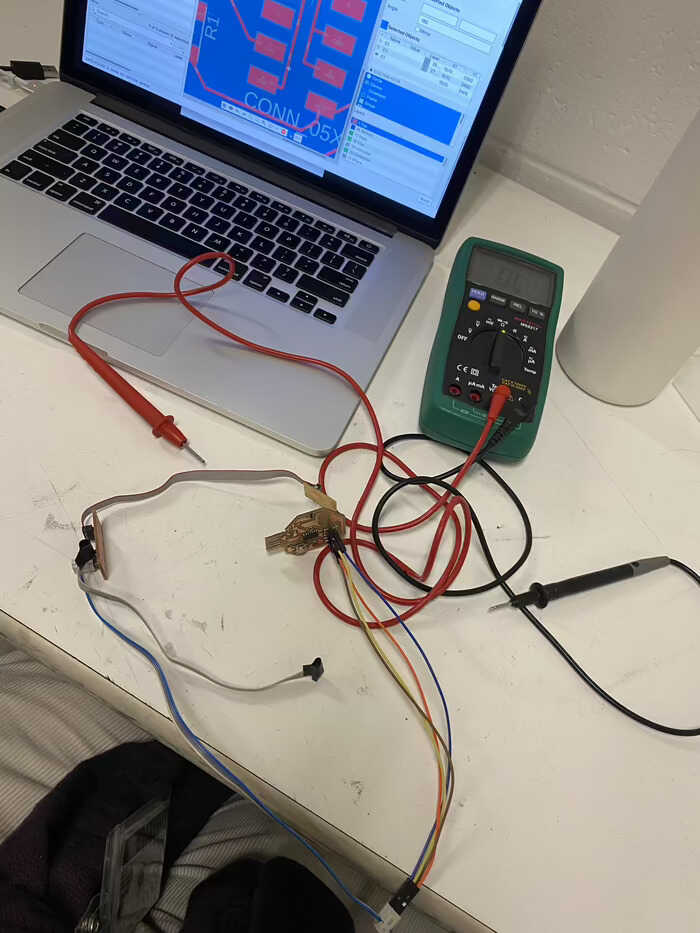
Jake said I could try pyocd instead of edbg and pointed me towards his documentation. The first hurdle was to find a converter between my 10-pin header (why I regret using it) and the jtag on the Atmel-ICE. Jake came through with the converter!
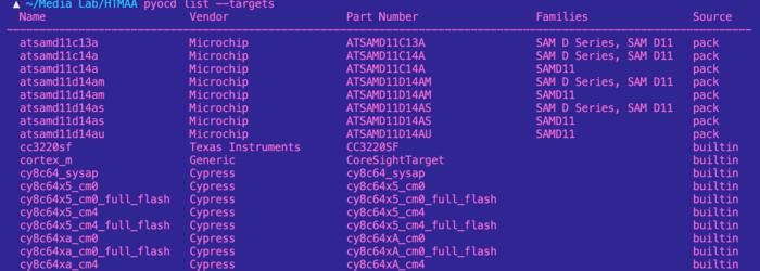
The second hurdle was installing pyocd. First, I had issues on my machine between Python 2 and 3. I tried to use pyenv to switch but it just wasn't working. I had to go home for the night because I had another class. On Wednesday morning I came back to try again. After trying 100 things, what finally got pyenv happy to reinstall xcode and run eval "$(pyenv init --path)". But I still had issues installing pyocd. After more time googling and trying things, what finally did the trick as updating pip. Yay, now I have pyocd! I tried to download the samd11 pack from a link Jake shared but it wasn't working. Eventually I found in the pyocd docs how to search for and install a pack. The bootloader I got from the link in the youtube video above.
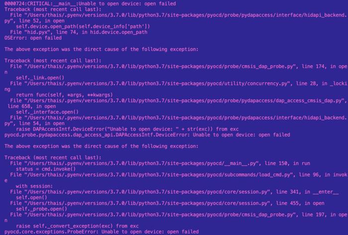
Moment of truth, I ran pyocd flash -t atsamd11c14a sam_ba_Generic_D11C14A_SAMD11C14A.bin aaand...
it hung.

I changed the orientation of the jtag adapter and tried again but got an error this time. And every subsequent time I tried, I also got the error. Sad.
I've run out of time to get it working, but it's ok, I can figure it out later. I learned a lot this week! I think this week could've gone better if:
- During electronics production, we could've redesigned a board in Eagle or KiCad without adding anything new to get used to that process. Then mill it. The assignment in week 2 was comparatively much smaller than this week's.
- Set up 2 millers at the start of the week. And slot sign-ups.
- Organize TA workshop/office hours ahead of time, for all sessions
- Set up peer schematics checking
- Explain in week 2 the relationship between the programmer we made then and the one we make this week. It seems Zach tried to help us out by having us making attiny programmers we could take home, but then Neil recommended we make samd11s this week so... moot.
I heavily referred to past student's documentations during this week to troubleshoot. I would use the class page search with some keywords. Here are most of those links:
- http://fab.cba.mit.edu/classes/863.16/section.CBA/people/Smith/week8.html
- http://fab.cba.mit.edu/classes/863.16/section.CBA/people/Costa/week13/index.html
- http://fab.cba.mit.edu/classes/863.12/people/sophia/project13.html
- http://fab.cba.mit.edu/classes/863.16/doc/tutorials/PCB_Rivets/
- http://fab.cba.mit.edu/classes/863.17/EECS/people/ekohrs/week10/index.html
- http://fab.cba.mit.edu/classes/863.14/people/dan_chen/electronics-design/index.html
- http://fab.cba.mit.edu/classes/863.14/people/dan_chen/input-devices/index.html
- http://fab.academany.org/2020/labs/agrilab/students/olivier-leroux/assignments/week06/
- http://fab.academany.org/2020/labs/ulb/students/robin-wilmart/assignments/week7.html
- http://fab.cba.mit.edu/classes/863.20/Architecture/people/GilSunshine/week06.html