Goal#
- Add an output device to a microcontroller board you've designed, and program it to do something
Result:#
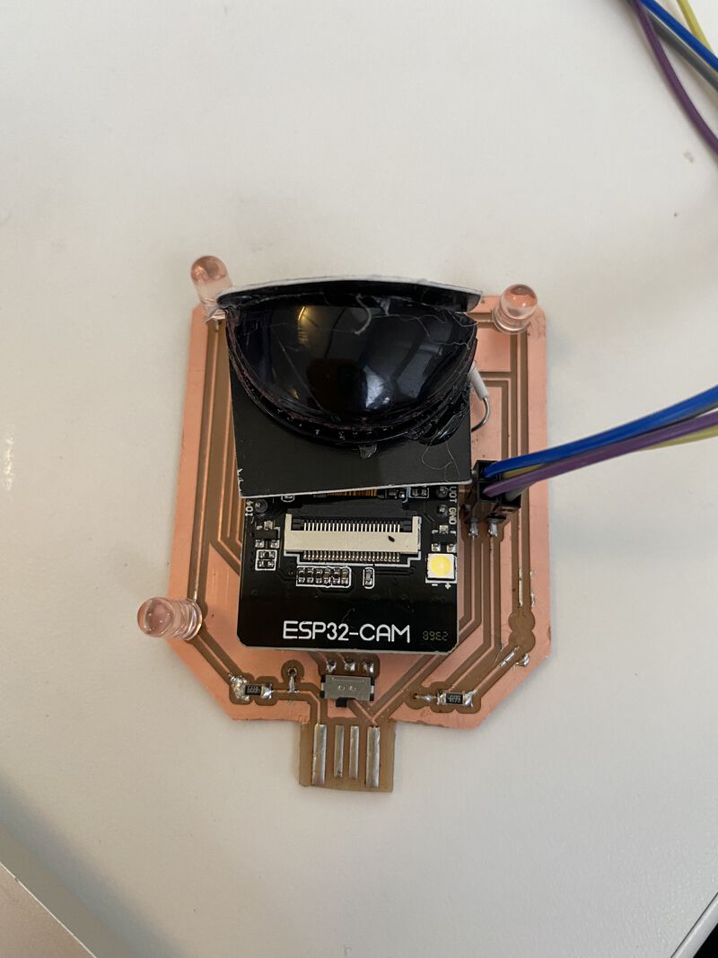


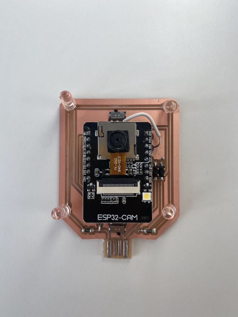
This week I reused my board desing from last week with the ESP32-CAM, but focused on the Infrared LEDs. This is by far my jankiest board so far so I'm going to detail all my mistakes here.
My first issue was loading my design into mods. Mods was freezing so bad I couldn't move the mouse or tab between text input fields. I ended up having to export my images at 500 DPI instead of 1000. It didn't seem to have any effect on my traces.
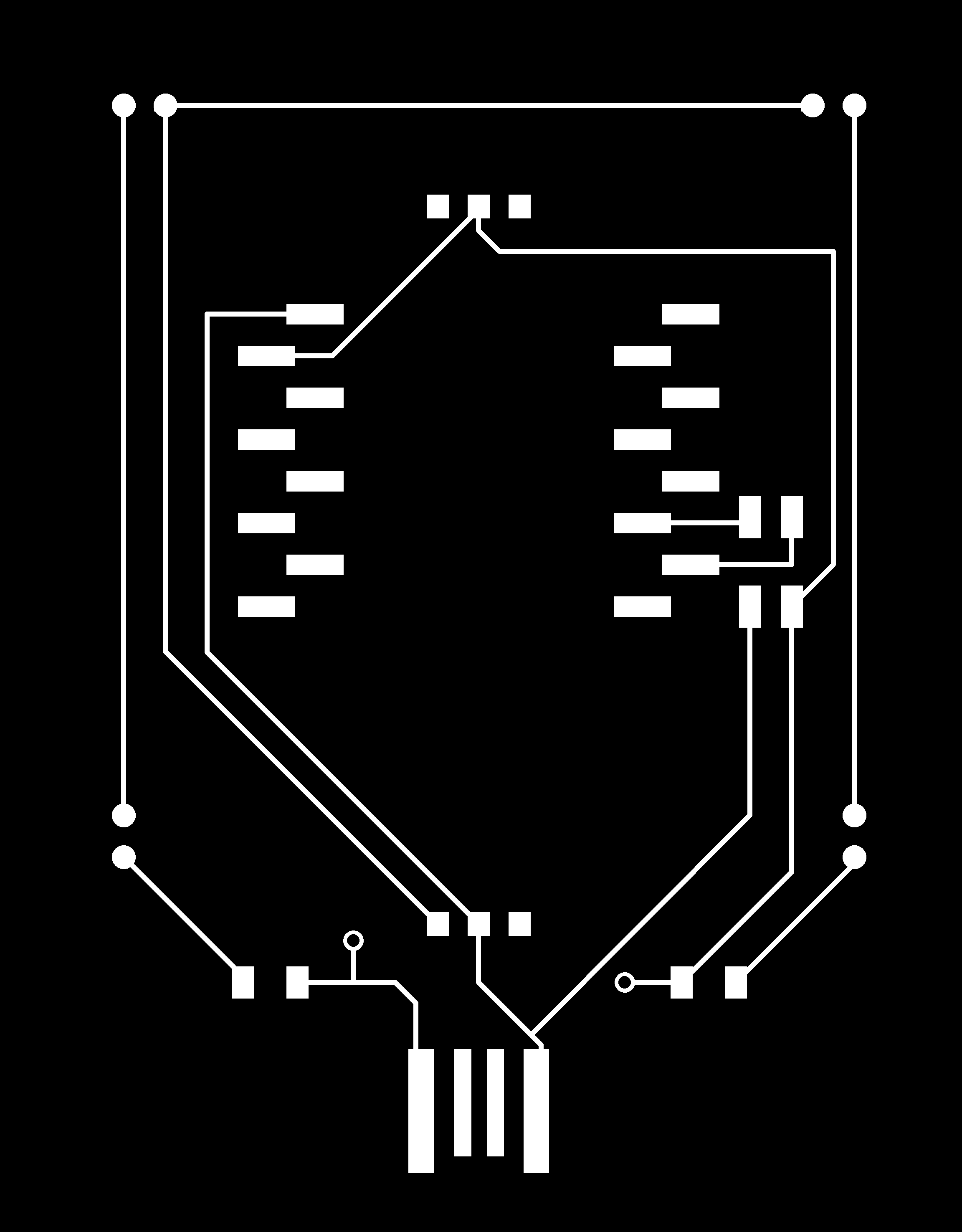
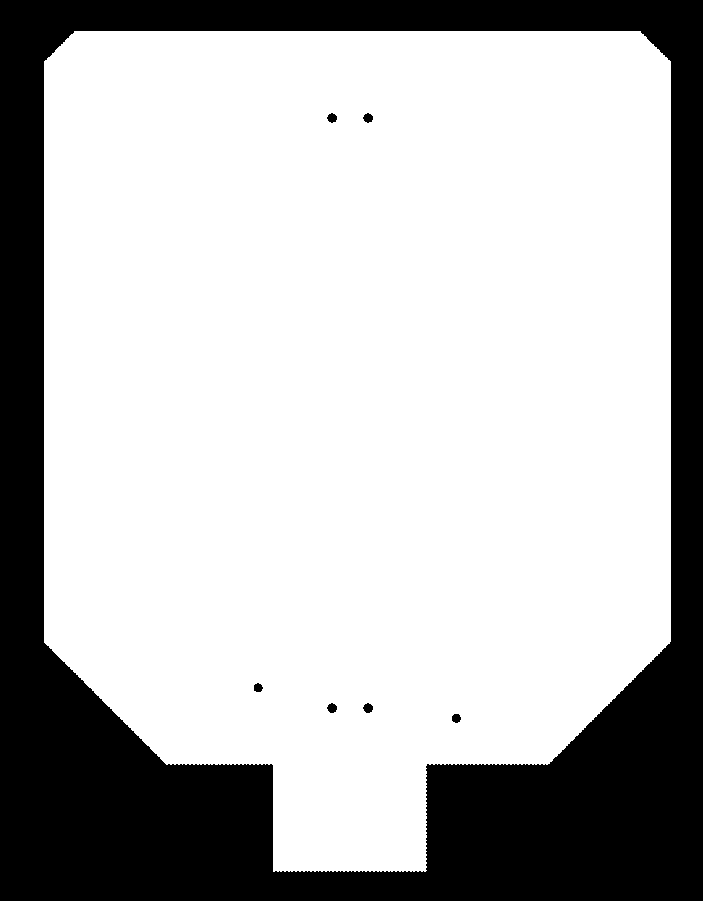
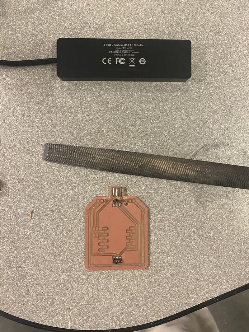
First, I forgot to set the via sizes in Fusion360 to 1/32". When I loaded my design into mods, it ignored the vias because they were too small. I thought I'd be smart by lying to mods and saying I was using a smaller endmill than I actually was. It made the vias BUT then the USB outline came out too wide to fit in my port. I had to manually file it down.
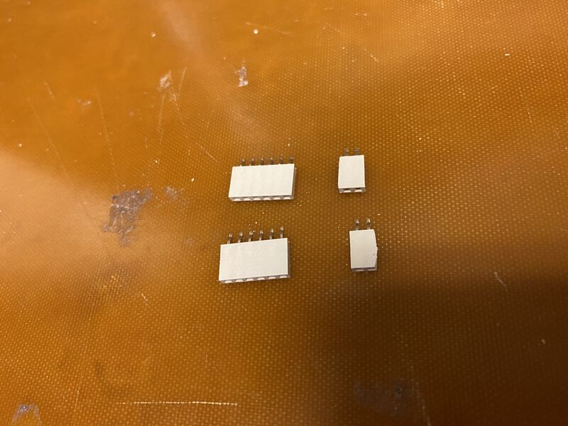
Then, I went on a search for headers to mount my ESP32. I even tried to make my own, not very successfully because they didn't match the footprint after bending the legs.
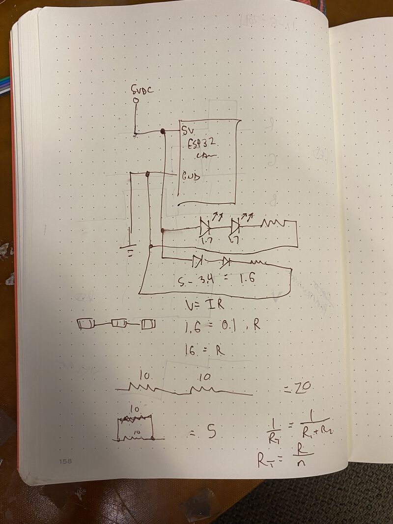
I looked at the datasheet for the IR LEDs I wanted to use and saw that the forward voltage was 1.7V and the continuous forward current as 100 mA. Zach said I should calculate my resistor value using a slightly lower current than the max. We arrived at a resistor value close to 49 ohms. The notes below also show Zach explaining to me that if that resitor was too high, I could later on solder a smaller resitor right on top of it.
Next, because I didn't want to mill the backside of my board, I cut the IR LEDs down and soldered them directly to the surface. I would not recommend doing this, the connection is extremely fragile. By the following week, my LEDs had fallen off.
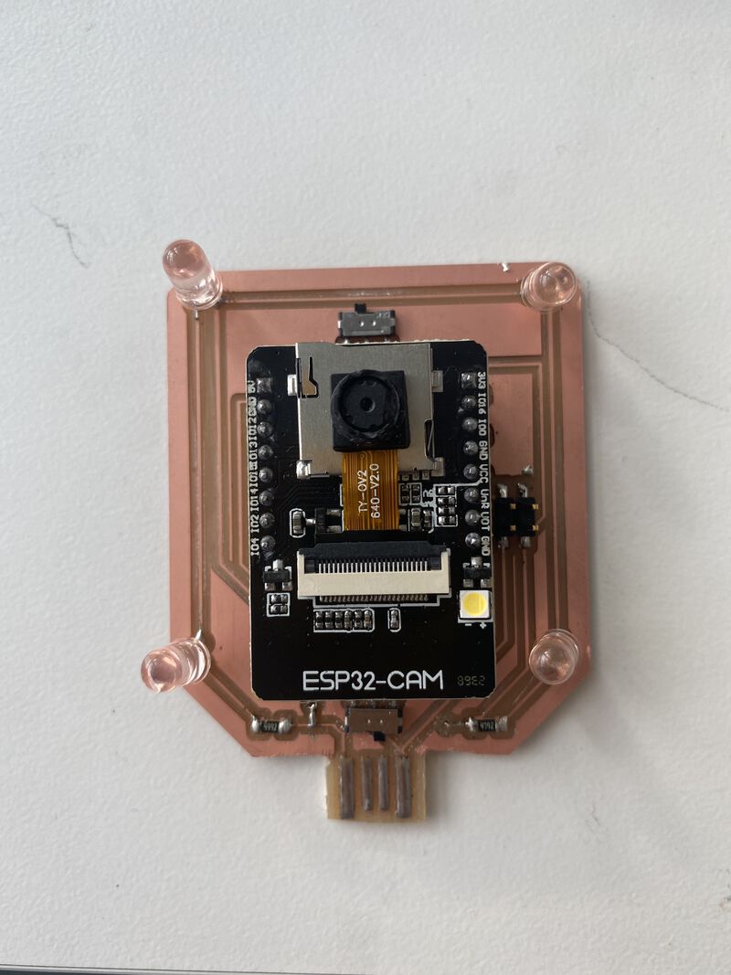
At this point I tried to program my board but it didn't work no matter what position my flashing mode switch was in. That's when I noticed I completely missed a trace! So I soldered some wired directly connecting one of the switch terminals to the GPIO0 switch. The middle terminal is connected to GND. Connecting GPIO0 and GND is how you put the ESP32 into flashing mode.
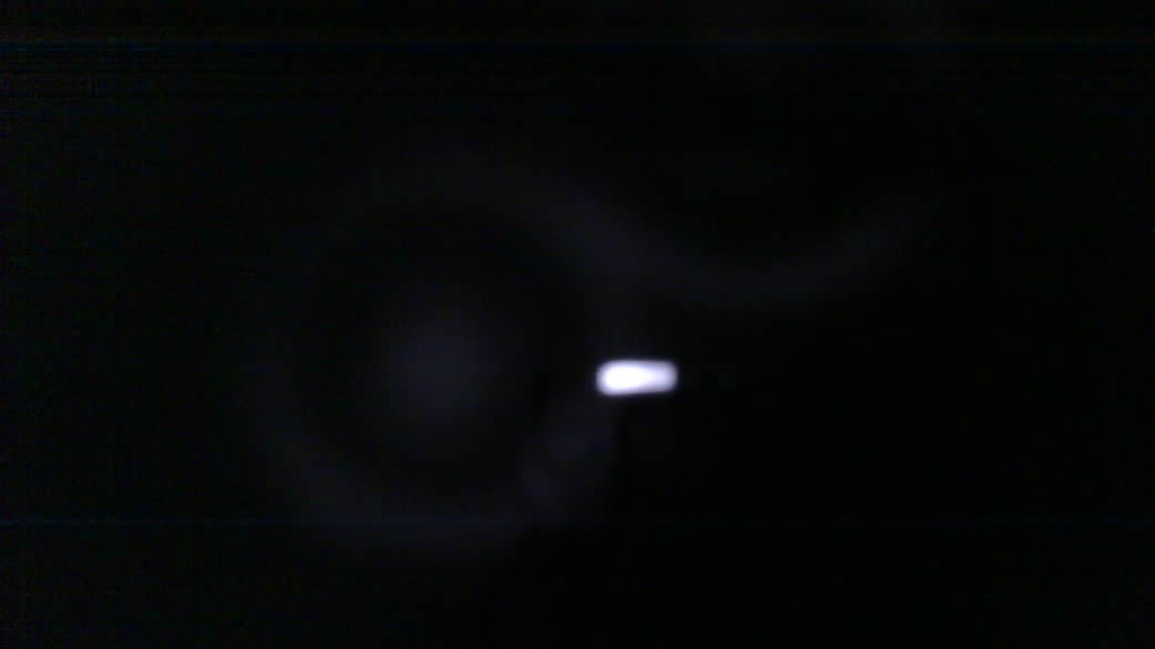
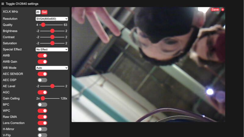
So now I wanted to test whether my camera really was seeing Infrared light. The previous week, I wasn't sure that what I removed was actually the Infrared filter. Zach grabbed a remote control for me and I was SO EXCITED when we could see the IR light from the control through my camera!
I also got a video that shows the IR LEDs turning on.
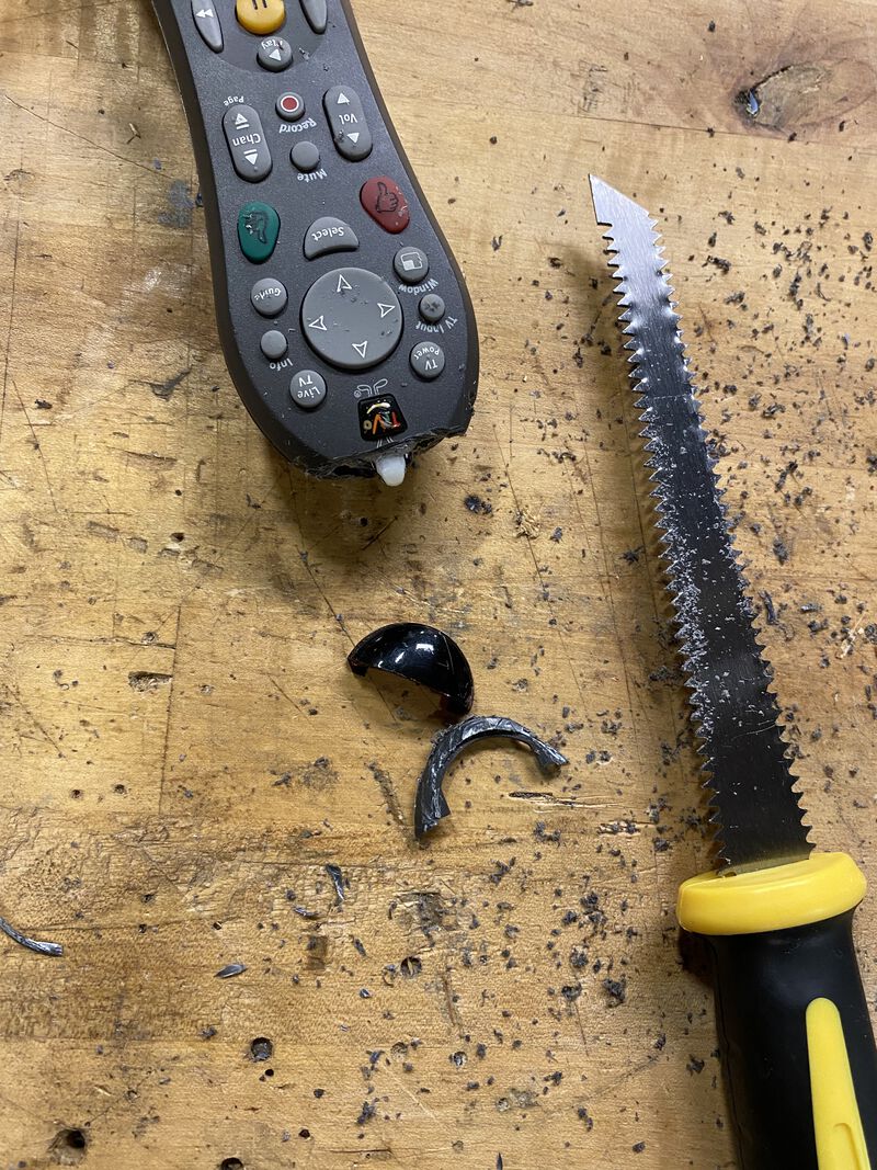
Next, I wanted to block visible light as much as possible. I went to the giveaway rack in the mailroom of E14 and found an old remote control. I hacked it apart until I could get the plastic filter over the IR LED. I think this filter blocks visible light but lets IR light pass through.
I threw together a makeshift enclosure for the ESP32.
And was thrilled that it seemed to be working! These are pictures taken using the ESP32 (on a low resolution though, sorry). You can even see the IR LED light on my hand in the second picture.
When I got home at night, I tested turning off all the ambient lights, having just the IR LEDs on, and standing back with some retroreflective tape. I was impressed that even from 5 feet away the tape was super bright!
I'm confident that I'll be able to use this camera and an updated version of my IR ringlight board to do object tracking :)