Final Project: Modal Analysis for Spinal Fusion Hardware Stability
My final project is to design a medical device to increase patient outcomes for spinal fusion surgery.
Over 480,000 Americans receive spinal fusion surgery yearly, but 13.9% of these surgeries are revised due to complications often caused by pedicle screw loosening.
Surgeons lack quantitative methods for determining screw stability intraoperatively, which helps predict screw loosening, instead relying on feel and intuition.
The objective is to prevent screw loosening by informing proper screw fixation.
The device will use modal frequencies (MF) to nondestructively provide quantitative metrics for screw stability by relating a screw’s resonant frequencies to its peak pullout strength (POS).
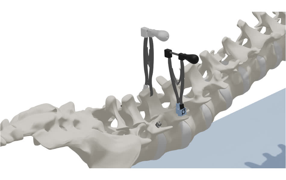
This system incorporates two tools: one excites the vertebral bone with vibrations, while the second receives resonant frequencies of the associated pedicle screw.
Both tools must be modular, accommodate a variety of surgical conditions, fit seamlessly into standard spinal fusion workflows, and deliver efficient, intuitive feedback to minimize operation times.
Surgeons will use fixation feedback to inform additional hardware integration or screw repositioning.
This is an existing project. A previous generation of the system was developed last year. The system has two devices: a sending and recieving module.
The recieving module is a tool that reads vibrations and characterizes frequency modes.
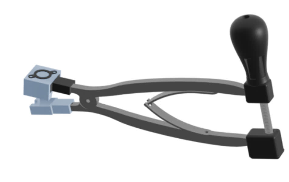
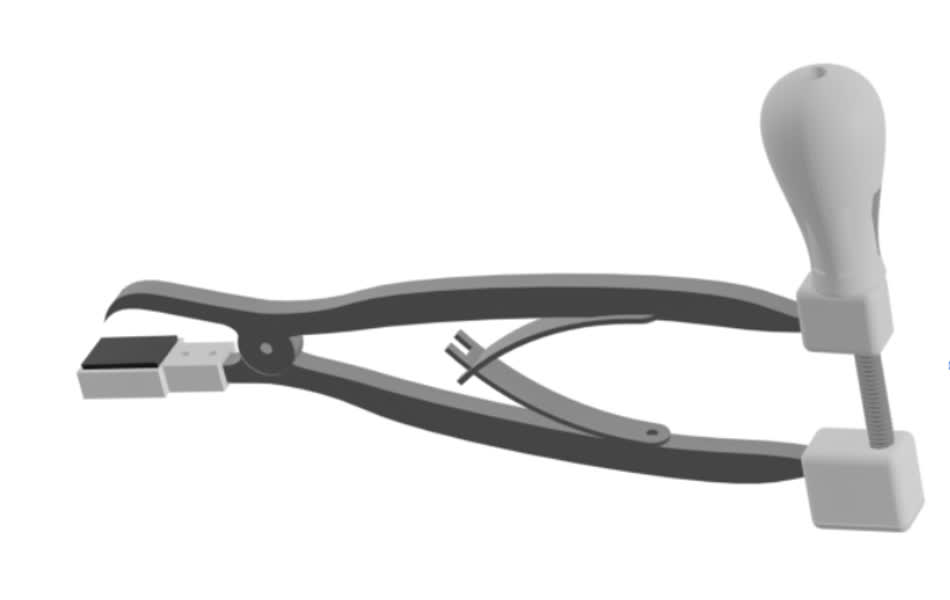
A prototype has veen developed which uses a piezoelectric device for signal reception and a transducer for the vibration sending module. Said tools both took the form factor of a mechanical forceps actuated by a leaf spring, and a lead screw mechanism could refine it's jaw width. See images below.
Both were very susceptible to inconsistent contact pressure between the sending and recieving module and the substrate material. Both were developed with a MKRzero wired system embedded in a breadboard that read out data to an SD card. This made data acquisition cumbersome.
The sending module uses a transducer to induce vibrations to the vertebrae that are transmitted to the pedicle screw while the receiving module uses a piezoelectric to sense mechanical impulses as vibrations. This system did not deliver reliable data. The remainder of this page is devoted to developments made this semester.
Recieving
Sending
Now Let's Get into it
Benchtop Testing and Design Considerations
This system must incorporate two tools: one that excites the vertebrae with vibrations and one that recieves the vibrations on the pedicle screw. The transducer itself is known to perform correctly. They're $8.95 a piece. That device can be found here: https://www.adafruit.com/product/1674. It's originally used for vibrational speaker that you can listen to by pressing them against your jaw or skull.
Therefore, all development on the sending module was mechanical design for bone surface contact and electrical design to integrate electronics in a pcb that allowed for wireless functionality with the xiao esp32c3.
The recieving module, however, required more significant development. Two options seemed viable: a better design/integration of the piezoelectric system or an integrated off the shelf IMU.
I decided to go with the accelerometer option first, since it seemed most interesting.
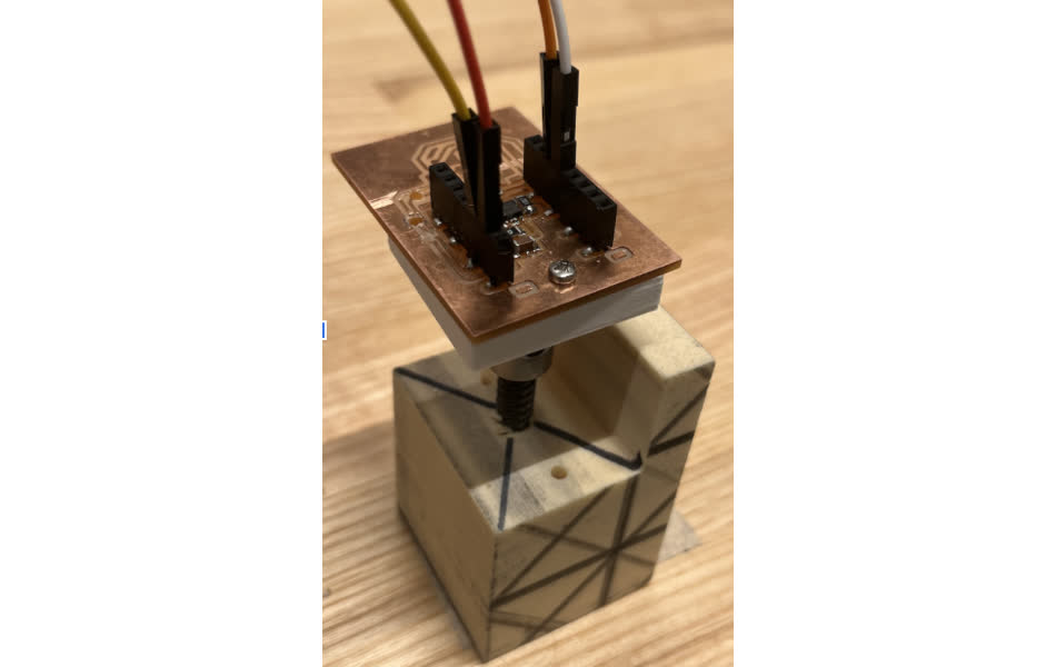
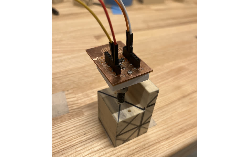
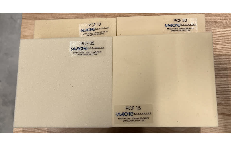
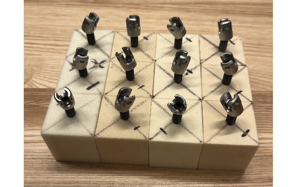
To test functionality, I used a bone substitute: high density polyeurathane blocks. These are 40 mm cubes, and looseness is simulated by varying pilot hole diameter and varying density. It has been previously established that the force required to dislodge these screws (indicative of fixation) is proportional to foam density and inversely proportional to pilot hole diameter.
I gathered some data by pressing the transducer against the foam sample. I used a basic matlab fast-fourier transform to try to identify consistent resonant frequencies. Below is a sample of the initial data. It was super inconsistent, and I think this is due to the low output data rate of the adxl343 (3200 Hz)
I did a similar benchtop setup with the piezoelectric
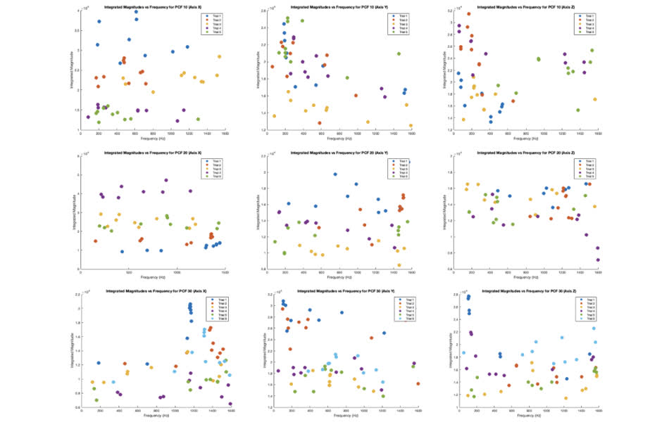
The data was slightly better, and peaks were identified corresponding to modes. The piezo sends data every 160 microsecond, which is a 6,250 Hz ODR, roughly twice that of the accelerometer.
Given this data, I decided to go forward with the piezoelectric sensor. They're $8.59 for a pack of 10. This is a 12 mm piezoelectric disc found here: https://www.amazon.com/uxcell-Acoustic-Transducer-Ceramic-Trigger/dp/B07RFVZVTS/ref=sr_1_9?dib=eyJ2IjoiMSJ9.guetFXIVvC0C8pyzYH65PH_PnvIvca5Az50DHyO89cPQZk2HS-nO8UMfMEZMTH-yS0eenLVp-s3Sr7gTRgapTPp4NO5aUPY-5vcSxFBtijtoWdWApIl5BXTDQy-wCNiKvU7T9wEbr9yvbxp-nxQxqaFiNCDBpqnQdr1kwpL_xH_RSF3V0D4AZ6DPtcQO0tz31hFWwr0RpMBhO6YeccLBlZiOMn8qGH33cWJORGpzEyja-CV4TzSonmlZpsLL1A1Spi2UIt97JLfwTCPM4Th8_BOeQ50-dQs37iiPW7tZkMsKK8vhtn3NispLG4umSxHdkvz7jccdvTAnNP8e8nq5Pe_gTmw4AN1ocjv2uUyR9k7dS8-IThs3hYode-mGRQ_8satZ1hxSKZlGmuMWoGxS7S3lOjpShRyyQ-zGYTq4YFo1W8PlZSNV9Hw3NnIjQl3W.YcygrWLH17u76vjnubF4iF4O5S62JqparzDfsxhQIa4&dib_tag=se&keywords=piezoelectric+disk&qid=1734501041&sr=8-9
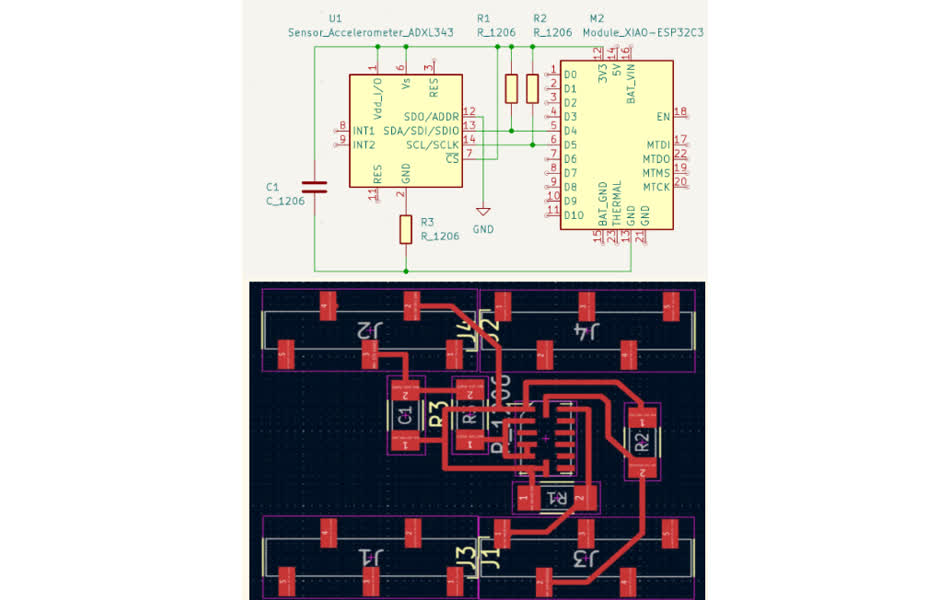
Electronics
For the sending module, I incorporated more breakout pins into my PCB for development capacity in future applications (pressure sensors, charging lights, etc.)
For the recieving module, I made the board flush so that it had a smaller form factor (no connectors). See the pcbs below.
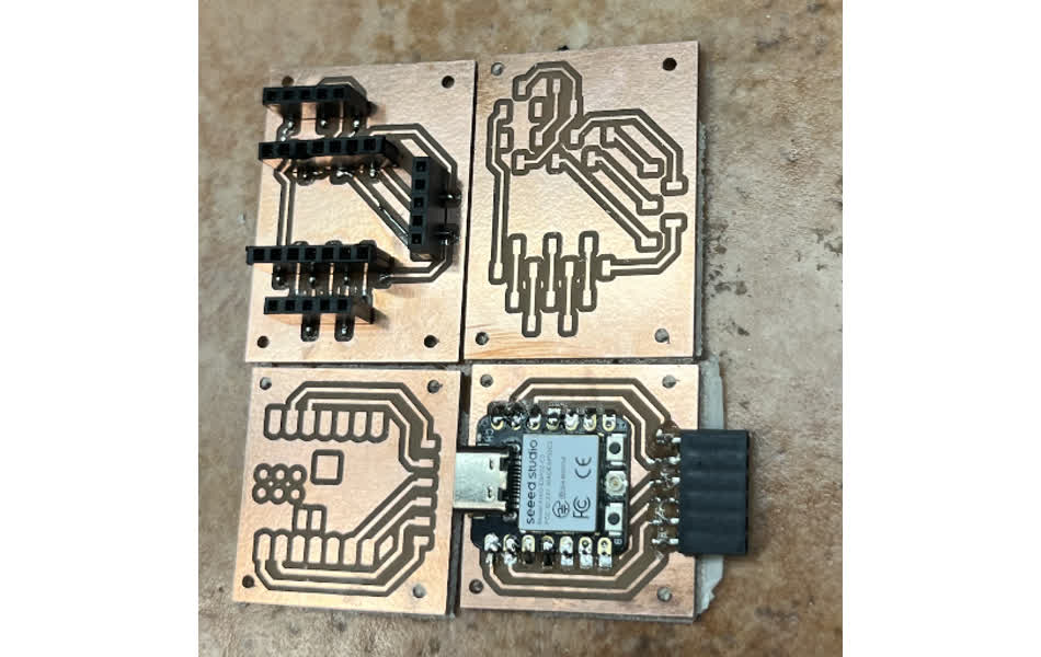
Both pcb's have through holes on their four corners so they can be mounted to their respective housings with M2 screws.
Both are powered by a 3.7 V lipo battery.
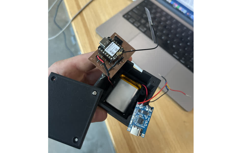
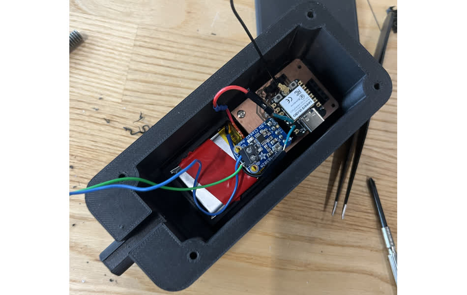
I ended up breaking the Xiao's that I soldered to the recieving module's pcb. Importantly, the power wire of the piezo must be tied to an analog pin with ADC capability. I used the extra sending module's pcb as a substitute. An image of the recieving module's electronics is below.
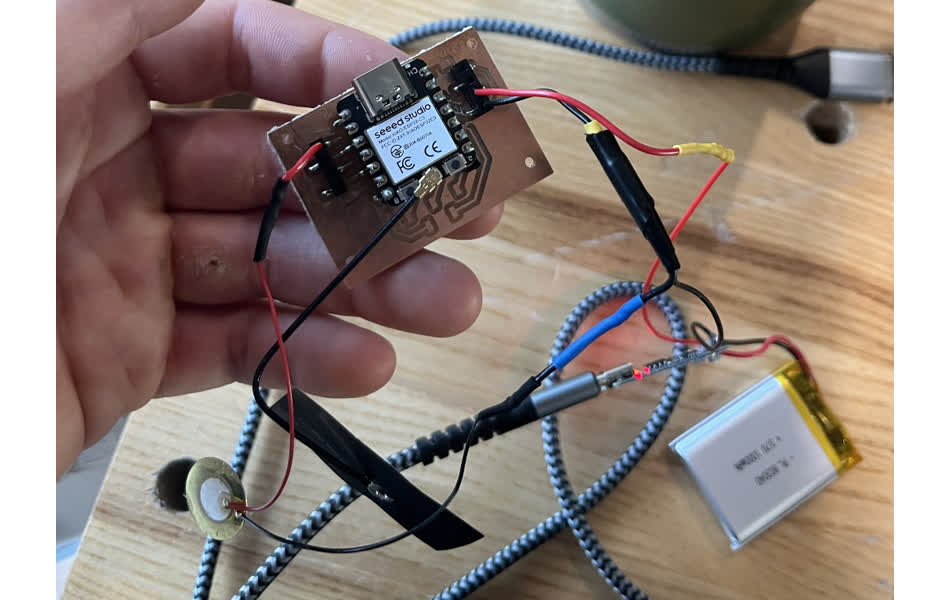
An image of the sending module's electronics is below. It includes an amplifier to inclease vibration amplitudes. That component is here, $7.49 for 5. https://www.amazon.com/dp/B00LNACGTY/ref=sspa_dk_detail_0?psc=1&pd_rd_i=B00LNACGTY&pd_rd_w=ba9em&content-id=amzn1.sym.8c2f9165-8e93-42a1-8313-73d3809141a2&pf_rd_p=8c2f9165-8e93-42a1-8313-73d3809141a2&pf_rd_r=YFBE6B1Y3C47PAF37D63&pd_rd_wg=B3dNM&pd_rd_r=157ef0ef-f0bf-45dd-a56d-a4f0bbc7812c&s=pc&sp_csd=d2lkZ2V0TmFtZT1zcF9kZXRhaWw
Mechanical Design
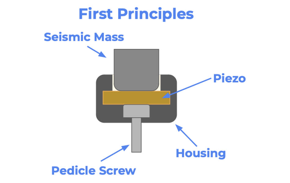
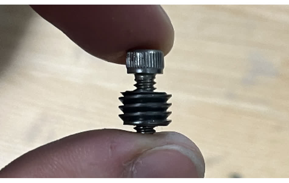
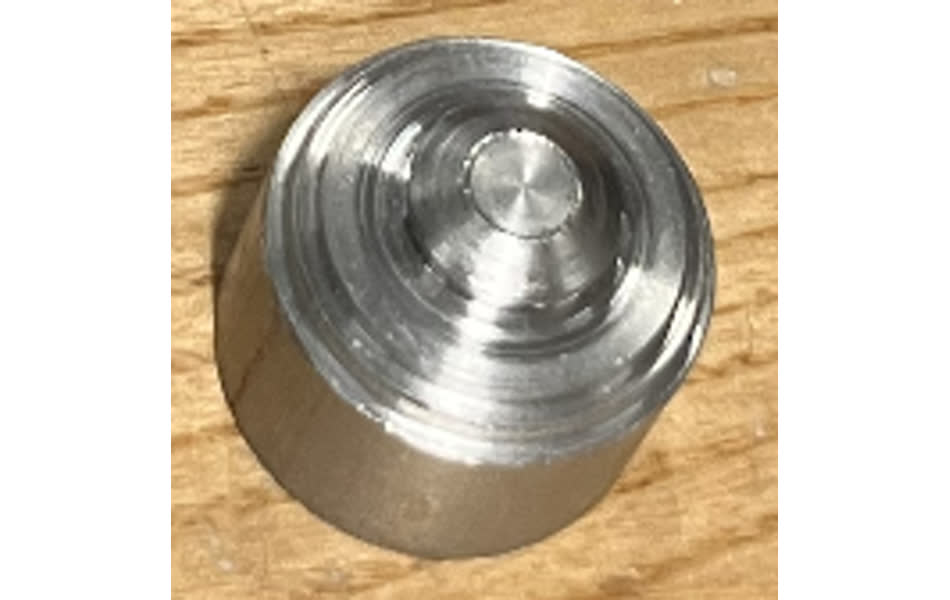
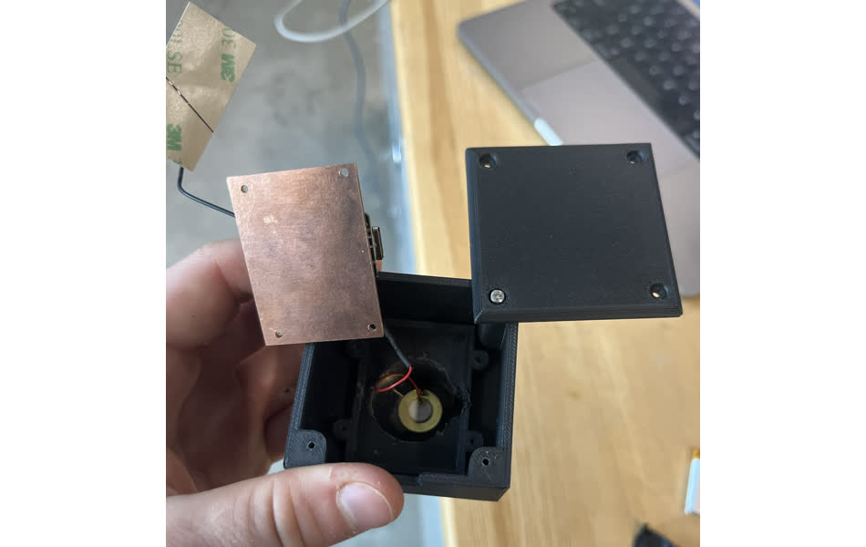
I started with the recieving module by iderntifying a method to constrain the piezoelectric to the pedical screw so that they vibrate together. I threaded the custom set screw that fits into the top of the pedicle screw, typically used to fasten the implant. I used a lathe to do this
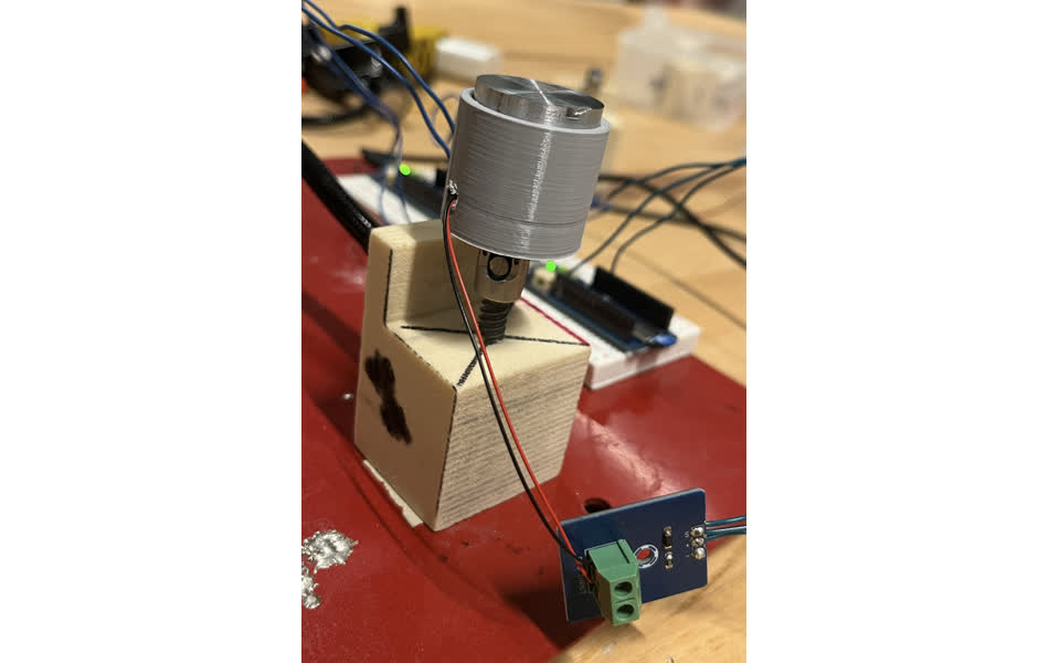
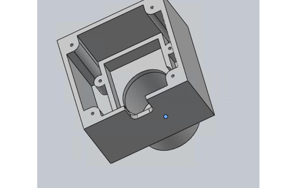
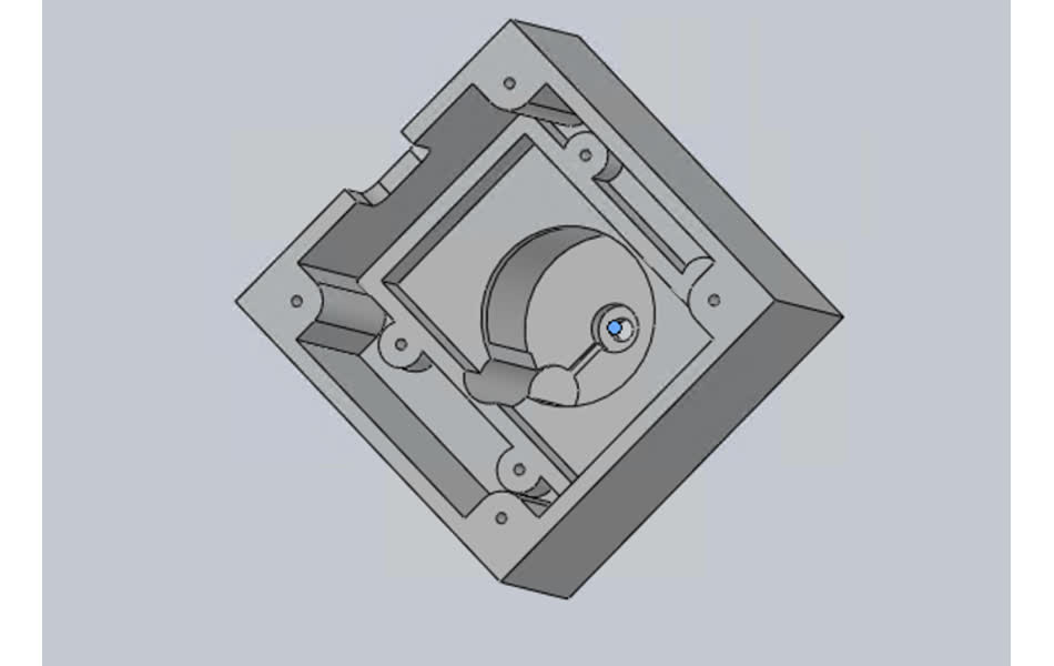
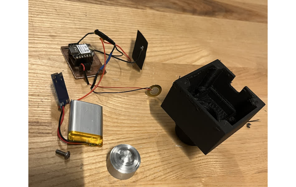
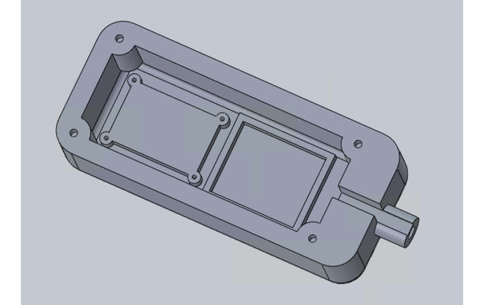
I then made the housing for all of the electronics and components using solidworks. The housing fits the seismic mass, battery, and pcb from bottom to top. There are mounting holes for the pcb and wire channels. I also made a cap. Metric Hardware fasteners were used. See images below.
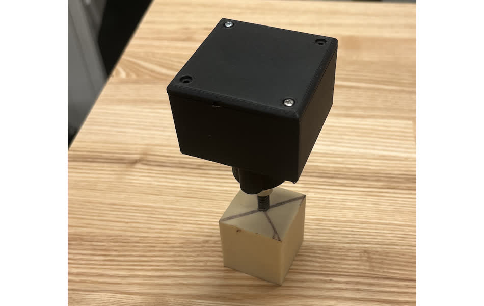
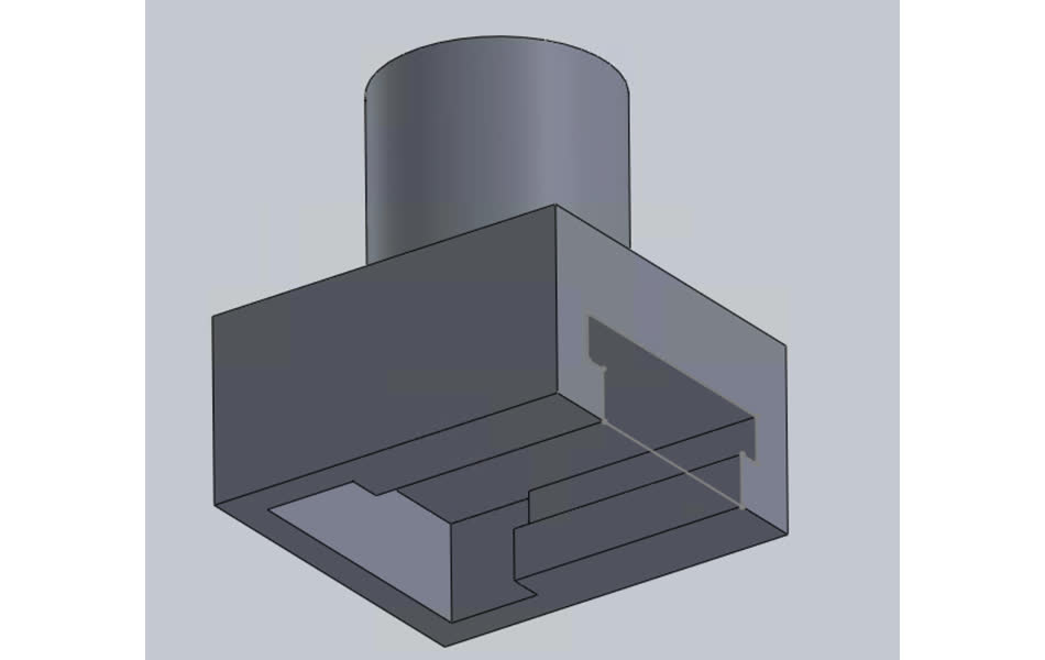
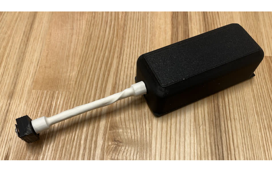
Next, I did the sending module design. The housing takes the form factor of a probe handle. See below.
The end effector clamps into the transducer for fixation.
Both components were constrained together by a 1/4-40 rod that threaded into respective holes.
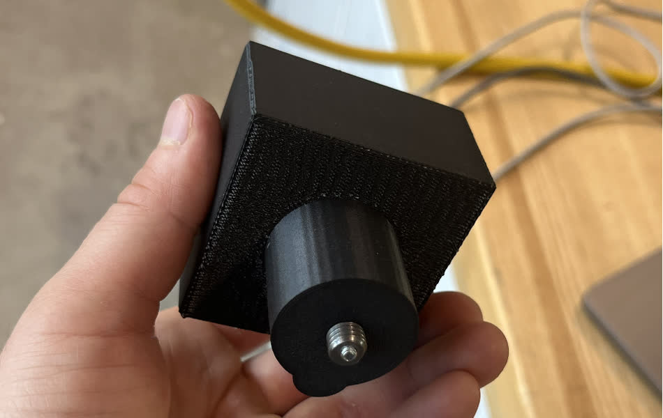
I used a large length of heat shrink to secure the wires running along the threaded rod. I also made a cap. The final assembly is below.
Software
I have attatched all of the arduino and python scripts below in the folder at the bottom.` The arduino script for the sending module initiates wifi communication and specifies a frequency sweep from 400-1500 Hz. Every 100 Hz, the sweep delays for vibration stabilization.
The arduino scrpt for the recieving module specifies a time for analog signal processing and sends that data over wifi to python.
Both scripts are programmed to their respective microcontrollers.
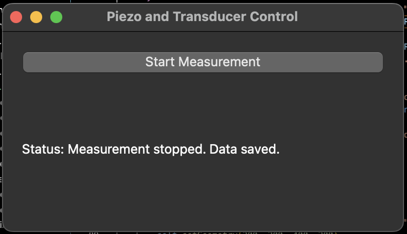
The python script allows for communication with the modules to perform their programmed functions and save data to a csv. This uses pySerial. PyQT was used to develop the GUI.
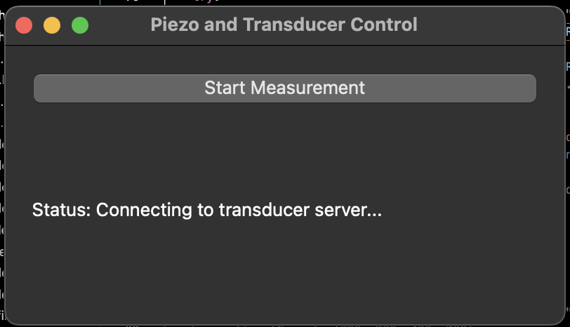
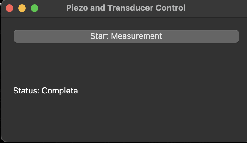
User interface
I used the pyQT interface developed in week 13 for the GUI that allows the user to use the tool with a single click. By clicking the button, the piezo recording starts, the transducer frequency sweep then runs, then the piezo quits sending data and a csv file is saved on the computer.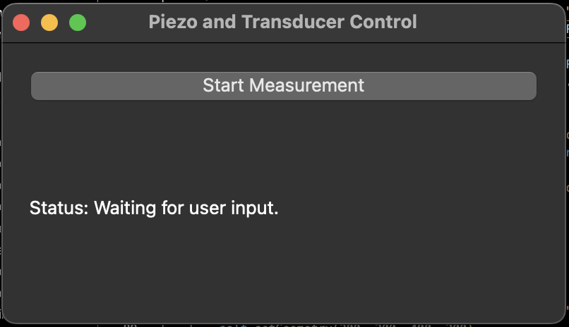
Data Processing
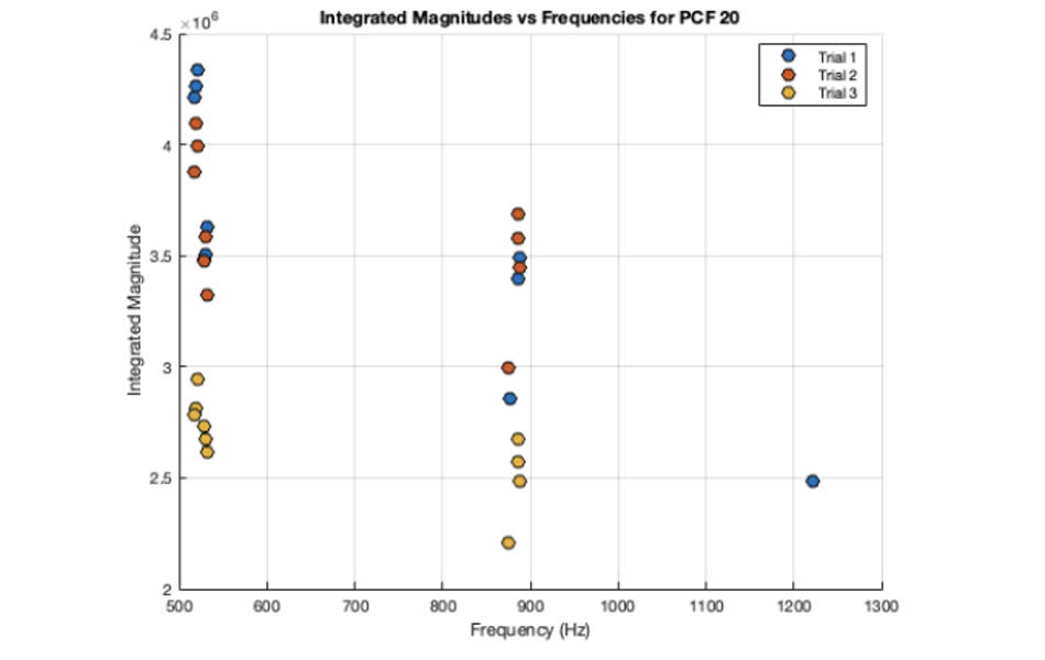
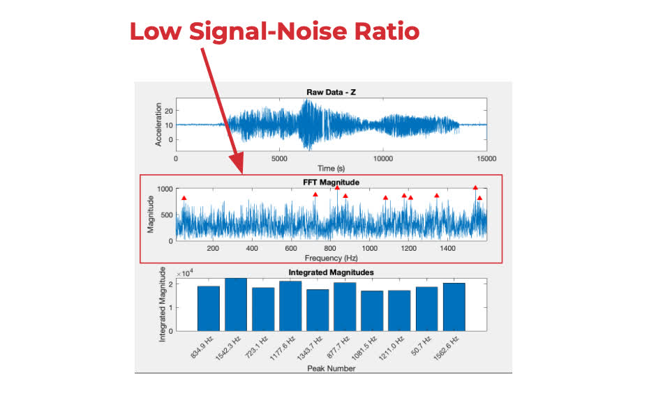
The last step was data processing. This was all done in matlab, and took a lot of iteration to find a suitable process. The main function is reading the data from the csv (sensor and time). Then, the raw data is plotted and a fast fourier transform is performed from matlab's FFT library.This alone produced a high signal noise. Data like that below was obtained initially.
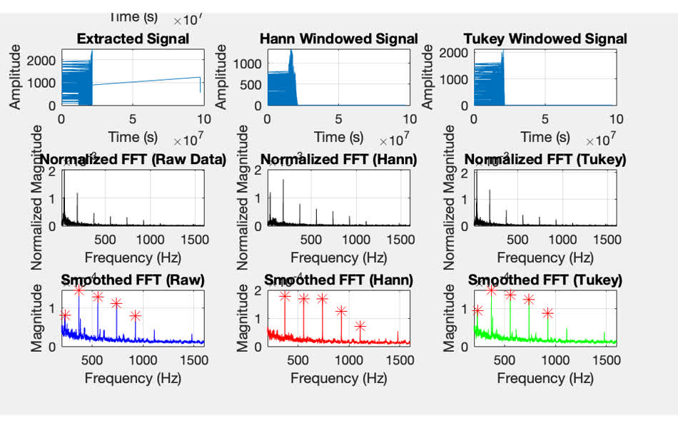
I performed windowing functions (turkey and hann) to prevent spectral leakage and reduce noise. This greatly improved the output, and solid peaks were identified.
Next Steps
I'm very happy with my progress, especially with data processing and wireless functionality. Next, I want to incorporate a pressure sensor to identify influence of pressure applied to the sending module. I want to implement battery charging with a corresponding LED system indicating charge. I want to improve the GUI to directly read out MATLAB results. Lastly, much more testing will be required to identify whether this system is capable of distinguishing a loose screw from a secure one. This will involve first testing with the polyeurethane then later with cadaver/butcher bones.Heres's all my files for the final project. Final Project Files