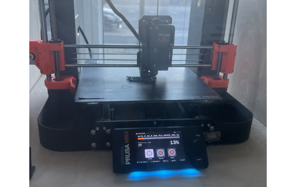
Project 11: Machine Week
This week was the course's group project. The Harvard section made a drawing machine to sketch caricatures on a white board.
My Contribution
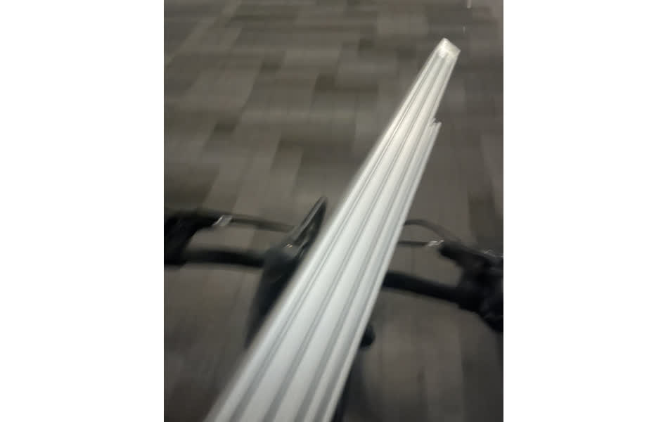
I started by bringing the stock materials and supplies for this week from recitation back to Harvard. It was super sketchy bringing these 8-foot long aluminum extrusions on the bike in the dark.
We brainstormed together as a team to come up with some concepts. The most simple design was a tube-shaped housing that the marker would fit in. It would be fixed to the core-xy carriage_front_generic fixture found at https://gitlab.cba.mit.edu/jakeread/machineweek-2024/-/tree/main/CAD/rotary_axis?ref_type=heads.

We also considered making a gripping or grabbing mechanism instead, but this would have also required multiple servos.
We landed on an design concept that would use a rack and pinion mechanism in which a vertically oriented marker and an eraser would be fastened to two separate rack gears. The teeth would face inwards to make contact on both sides of a single pinion gear.
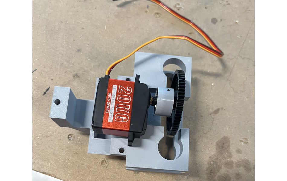
I started by designing the housing for the servo motor.
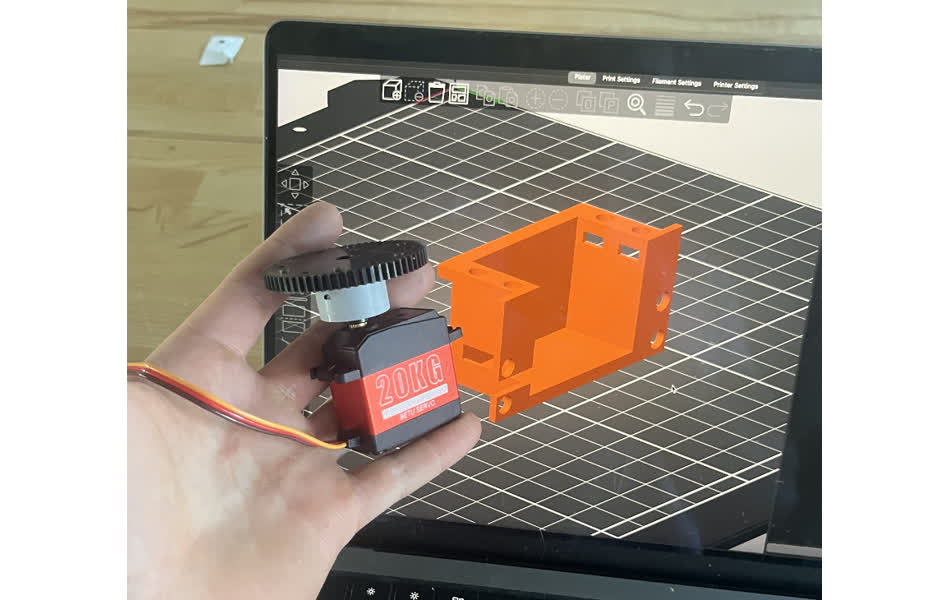
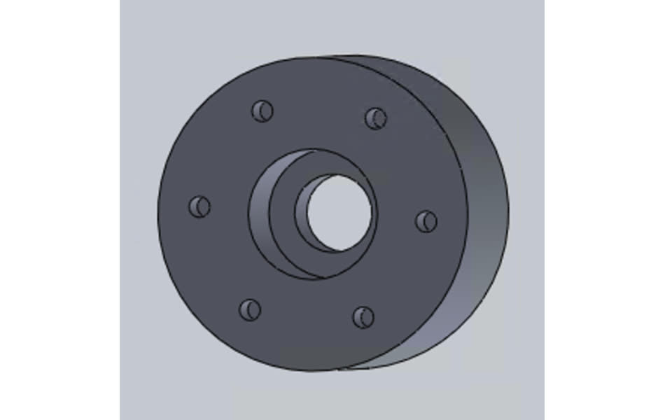
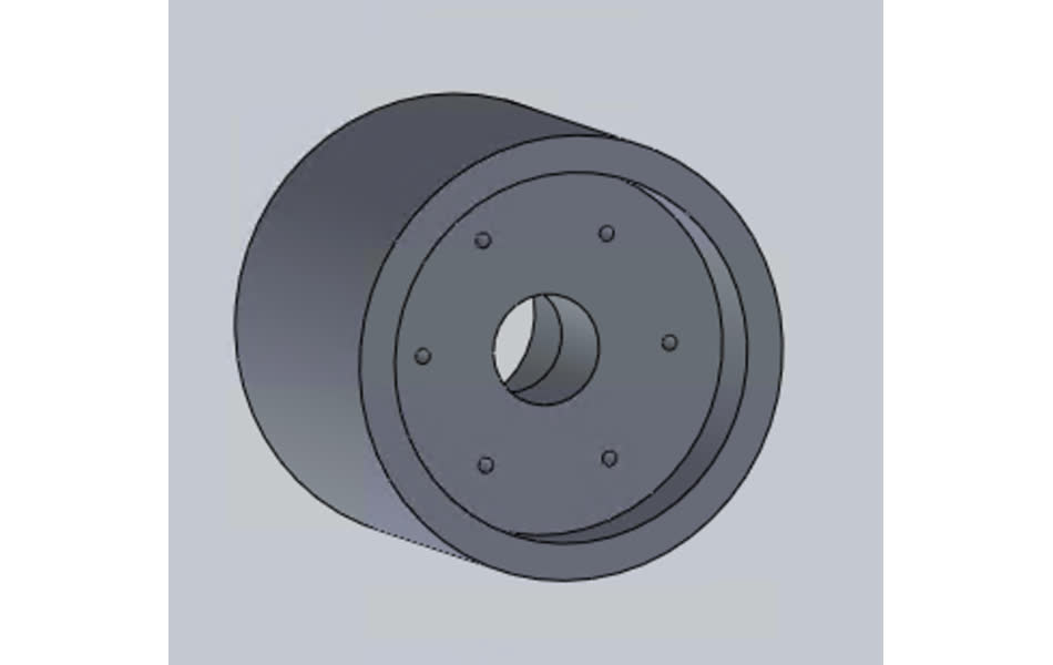
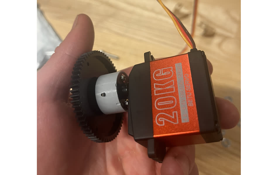
I then designed a coupler to trransmit rotation from the servo to the pinion gear.
Alex designed the housing for the rack and pinion marker drivers. We had some communication issues, and our two designs were incompatible.
So we decided to do a design spint in order to independently design two systems that would allow our servo-actuated rack and pawl system to be fixed to the core xy gantry mount.
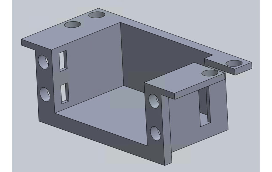
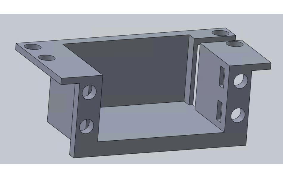
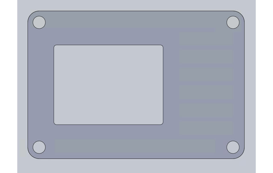
I came up with this design
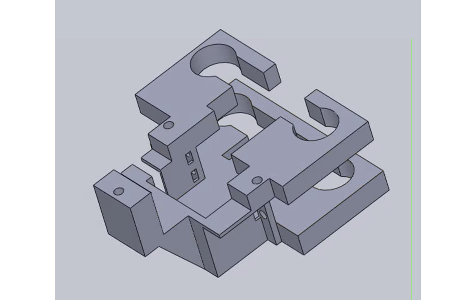
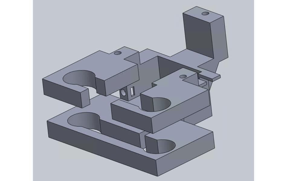
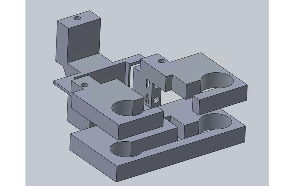
My design had two problems: the cutouts for the markers were too large because I used the diameter as the radius, and I forgot to include slots to accomodate the mounting flanges on the servo.
Alex's design wasn't perfect either. It was a bit flimsy, and the torque exerted on the markers as they drew on the board caused the fixture to bend, which would distort images.
We were running out of time, so we decided to simplify our design so that we could laser cut it rather than queing another 5+ hour 3D print.
We made a bracket that would fix the servo in place perpendicular to the orientation of the markers. This bracket mounted onto the aluminum extrusion. We used the servo arm from the kit to lift and drop the marker housing, allowing us to draw.
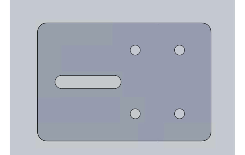
Here's the bracket to hold the servo
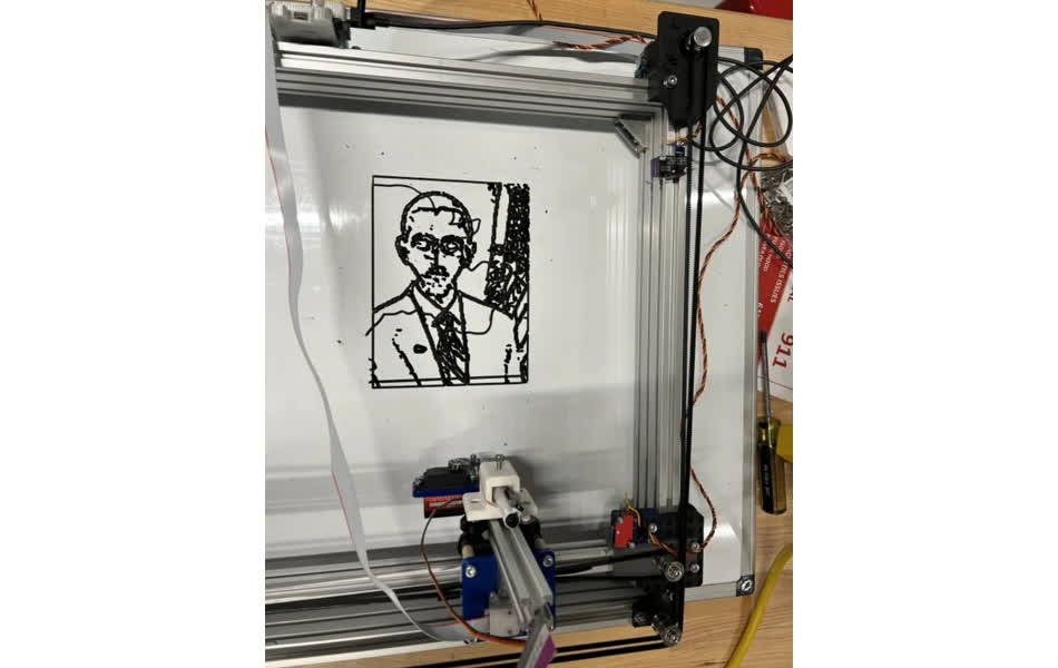
Here's how it looks all together
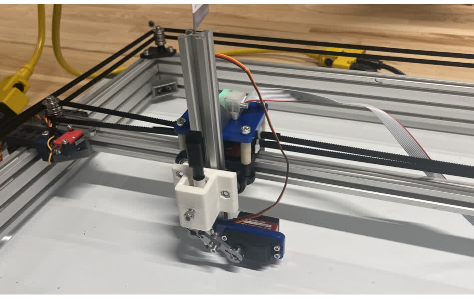
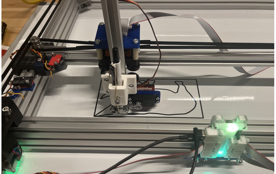
This worked, but it was less that ideal. We ran out of time to make a system that would allow us to both draw and erase our sketches without manually replacing the marker with the eraser or vice versa.
Having started the designs a few days earlier would have helped.
Heres's all my files for this week Week 11 Files/a>