Project 1: CAD
This was the first week of class. We discussed computer aided design. This is likely one of the most familar topics of the course for me. I have experience with solidworks and creo CAD software. I'm interested in potentially using fusion360, which would be a good learning oppportunity.
Final Project
My final project is to design a medical device to increase patient outcomes for spinal fusion surgery.
Over 480,000 Americans receive spinal fusion surgery yearly, but 13.9% of these surgeries are revised due to complications often caused by pedicle screw loosening.
Surgeons lack quantitative methods for determining screw stability intraoperatively, which helps predict screw loosening, instead relying on feel and intuition.
The objective is to prevent screw loosening by informing proper screw fixation.
The device will use modal frequencies (MF) to nondestructively provide quantitative metrics for screw stability by relating a screw’s resonant frequencies to its peak pullout strength (POS).
This system incorporates two tools: one excites the vertebral bone with vibrations, while the second receives resonant frequencies of the associated pedicle screw.
Both tools must be modular, accommodate a variety of surgical conditions, fit seamlessly into standard spinal fusion workflows, and deliver efficient, intuitive feedback to minimize operation times.
Surgeons will use fixation feedback to inform additional hardware integration or screw repositioning.
I am working on this project with another Harvard Student (who's not in HTMAA) in Harvard's Bionics Lab. I will be working on the recieving module: the tool that reads vibrations and characterizes frequency modes.
A prototype has veen developed which uses a piezoelectric device for signal reception and a transducer for the vibration sending module.
The sending module uses a transducer to induce vibrations to the vertebrae that are transmitted to the pedicle screw while the receiving module uses a piezoelectric to indentify the resulting frequency modes of the pedicle screw, which was translated into a screw pullout strength.
The pedicle screw stability quotient (PSSQ), or measure of predicted implant fixation, was indicated on a 1 through 10 scale on an external screen. Both devices resembled and functioned similar to surgical forceps.
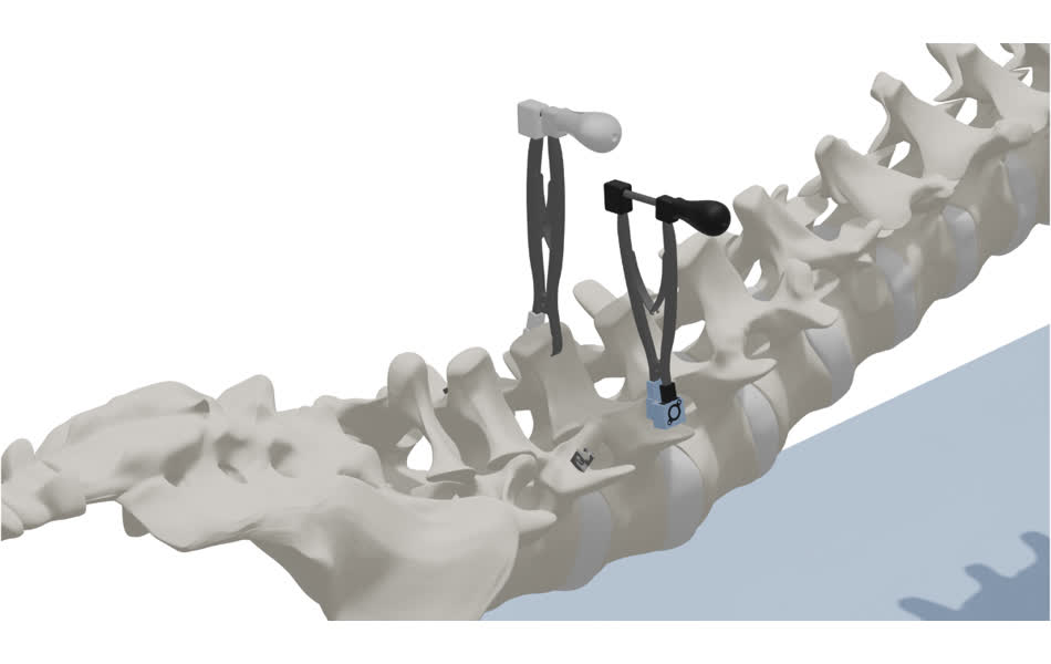
The DPT clamps on to the spinous process, while the DPG clamps to the tulip head of the pedicle screw (full workflow in Figure 2).
The pressure application of the transducer and piezo in the DPT and DPG respectively are applied by a leaf spring and adjusted by a lead screw system.
Below are some CAD renderings of the device.
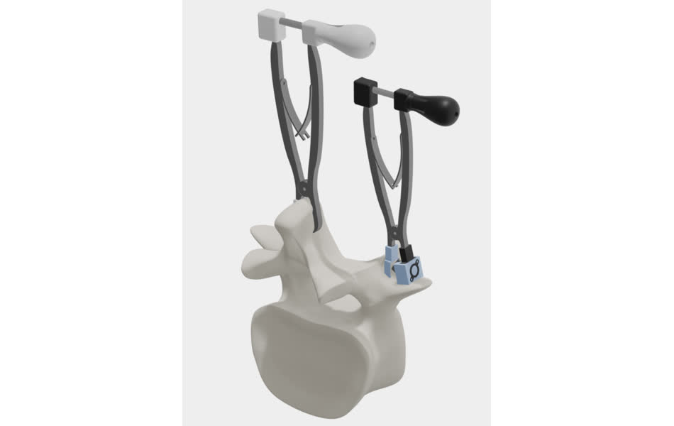
System Vision
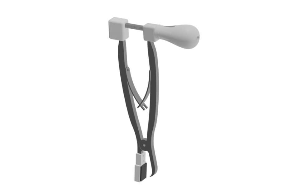
Transmission Module
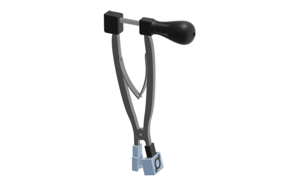
Recieving Module
There are multiple form factors that this two-tool system could take. Currently both modules resemble medical forceps with electronics-embedded end effectors. The sending module needs to contact exposed vertebral bone features.
The device currently clamps on to the spinous process, but this is often harvested during the operation for bone grafting. Alternative design considerations include a refined clamp, a probe, or a post. The clamp would necessarily be smaller,
and secure to a variety of surfaces and bony features. The probe would facilitate direct contact between the transducer and any exposed bone surface, but would require pressure feedback to avoid damping.
This pressure feedback could be electronic, (strain gauge), or mechanical (spring force meter or mechanical stop). The post would snugly fit into a small pilot hole and transmit vibrations from at attached transducer.
This could be modulated through an external console.
The receiving module likewise has multiple design considerations. The first is to fix an IMU to the pedicle screw for vibration analysis. Expected vibrations are ~700-1200 Hz, so a very sensitive IMU is necessary.
By the Nyquist Theorem, the output data rate must be 2X the max expected frequency, excluding safety factors. The second option is to use a piezo that contacts the tulip cap but remains stationary itself.
The stationary requirement presents a design challenge, for which a solution might be a linkage arm system. Lastly, laser vibration measurement could be used in the form or laser doppler vibrometry or speckle pattern interferometry.
These systems could be costly and complicated.
Heres's all my CAD files for this week
Week 1 Files/a>