Project 8: Input Devices
This week was all about input devices. I made a breakout board for the ADXL 343. I hope to use this for my final project for vibration sensing.
Let's Start with the Group Project
The group project was to probe input devices for digital and analog signals.
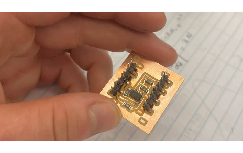
Making the Accelerometer Breakout Board
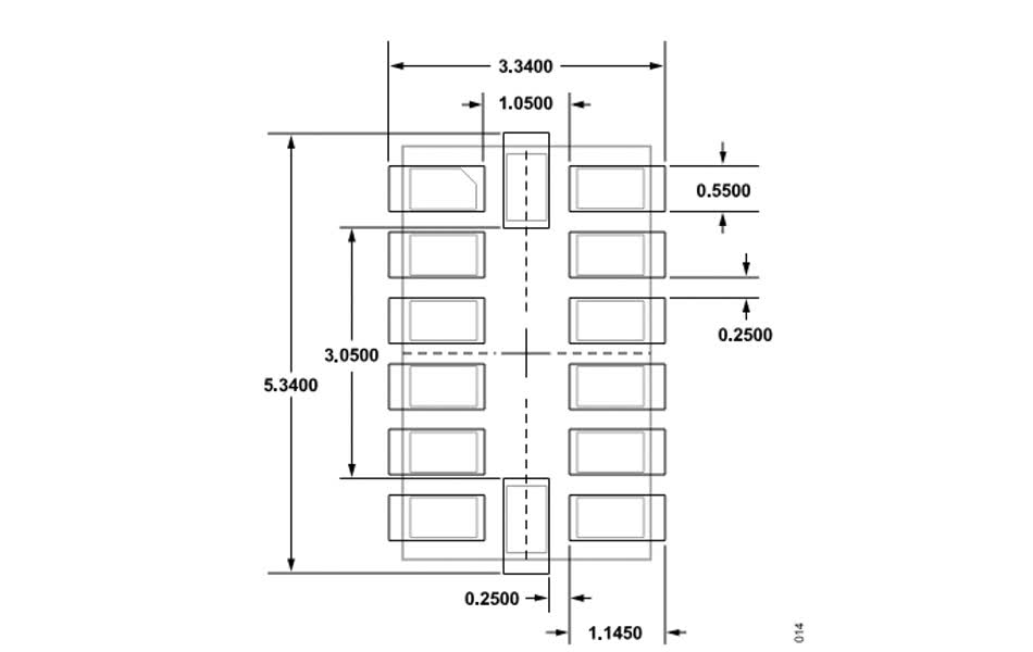
I started by attending Anthony's office hours for soldering small components. The ADXL 343 has tiny pads that are 0.55 mm wide and spaced 0.25 mm apart. The pads are also concealed on the underside of the board.
It was necessary to use solder paste, which I had never used. It's basically a bunch of solder pellets suspended in flux. You paste it over the desired pads with surprisingly low accuracy (the flux can blob up and connect adjacent pads). Heating up the past with the heatgun (fancy, super hot hairdrier) at temperatures around 270-330 celcius will evaporate the flux, melt the solder, and generally cause the solder to form on the pads to prevent shorts.
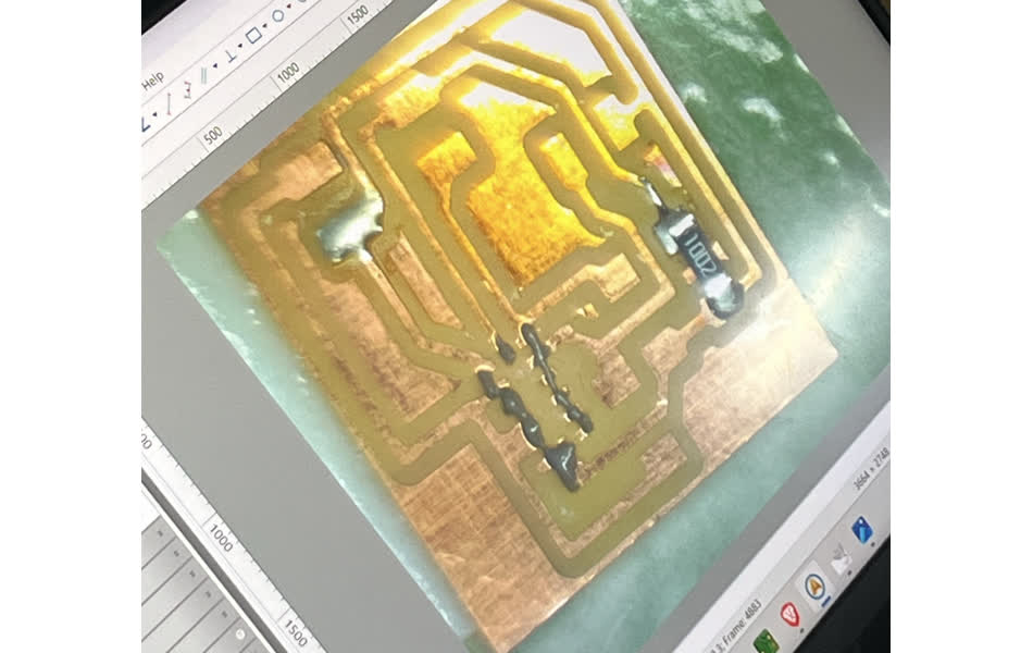
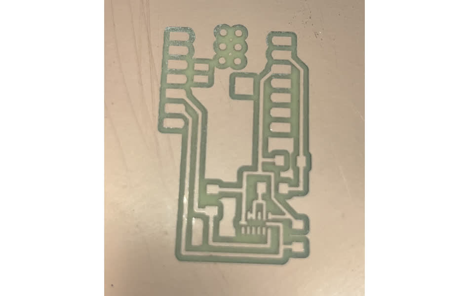
When I was fairly confident I knew how to solder the ADXL 343, I fabricated my board. As usual, I had a few problems. I started by milling with the v-bit, and realized the traces were not being cut between the pads of the ADXL 343.
With Anthony's help, we realized the footprint was slighly incorrect: the pads were too large and the gaps between them were too small for the mill to isolate them. We thinned out the pads so that a 1/64" end mill could get in there and make the necessary traces.
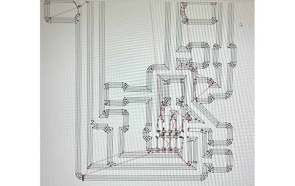
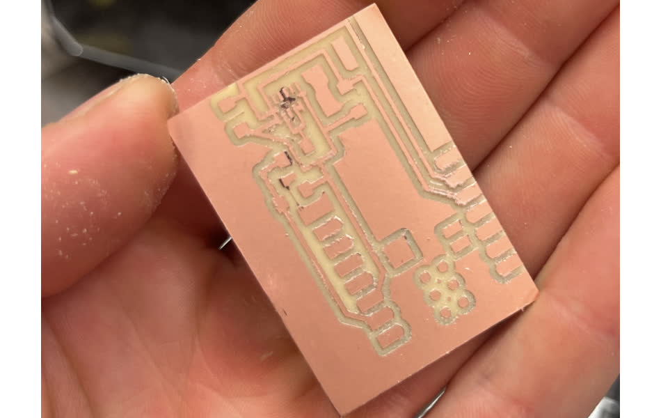
The tool path looked correct, so I milled my board. The mill was dull so the edges weren't perfect, but scraping the surface of the copper with a spackle knife revealed the traces. The cuts weren't quite deep enough near around the pads.
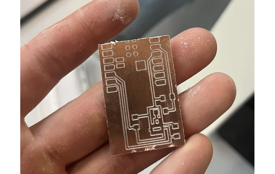
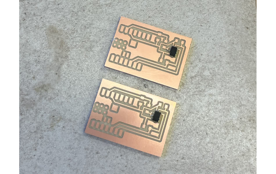
I tried again with a different end mill, and made sure to pull the end mill down to the copper harder. This worked great!
I soldered on the ADXL 343 and remaining componets with solder paste.
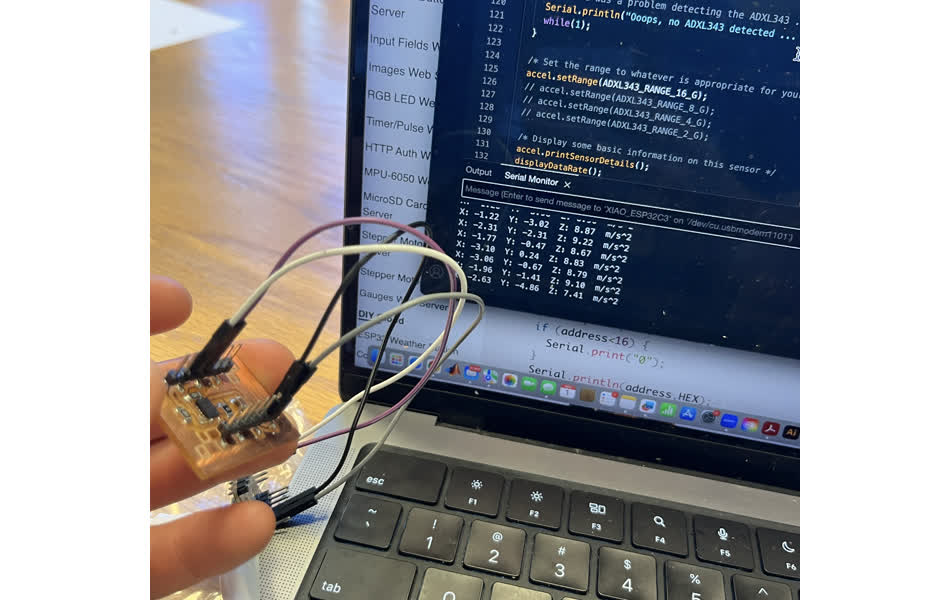
Now it was time to connect to my board through the Arduino IDE. I started by downloading the adafruit_sensor and adafruit_adxl343 libraries. I then tried to run the sensortest example script in the latter library. My code compiled, but nothing printed in the serial monitor or serial plotter. The code is below.
Code Display
        #include
            #include
            #include

            #define ADXL343_SCK 5
            #define ADXL343_MISO 4
            #define ADXL343_MOSI 11
            #define ADXL343_CS 10

            /* Assign a unique ID to this sensor at the same time */
            /* Uncomment following line for default Wire bus      */
            //Adafruit_ADXL343 accel = Adafruit_ADXL343(12345);

            /* NeoTrellis M4, etc.                    */
            /* Uncomment following line for Wire1 bus */
            Adafruit_ADXL343 accel = Adafruit_ADXL343(12345, &Wire);

            /* Uncomment for software SPI */
            //Adafruit_ADXL343 accel = Adafruit_ADXL343(ADXL343_SCK, ADXL343_MISO, ADXL343_MOSI, ADXL343_CS, 12345);

            /* Uncomment for hardware SPI */
            //Adafruit_ADXL343 accel = Adafruit_ADXL343(ADXL343_CS, &SPI, 12345);

            void displayDataRate(void)
            {
              Serial.print  ("Data Rate:    ");

              switch(accel.getDataRate())
              {
                case ADXL343_DATARATE_3200_HZ:
                  Serial.print  ("3200 ");
                  break;
                case ADXL343_DATARATE_1600_HZ:
                  Serial.print  ("1600 ");
                  break;
                case ADXL343_DATARATE_800_HZ:
                  Serial.print  ("800 ");
                  break;
                case ADXL343_DATARATE_400_HZ:
                  Serial.print  ("400 ");
                  break;
                case ADXL343_DATARATE_200_HZ:
                  Serial.print  ("200 ");
                  break;
                case ADXL343_DATARATE_100_HZ:
                  Serial.print  ("100 ");
                  break;
                case ADXL343_DATARATE_50_HZ:
                  Serial.print  ("50 ");
                  break;
                case ADXL343_DATARATE_25_HZ:
                  Serial.print  ("25 ");
                  break;
                case ADXL343_DATARATE_12_5_HZ:
                  Serial.print  ("12.5 ");
                  break;
                case ADXL343_DATARATE_6_25HZ:
                  Serial.print  ("6.25 ");
                  break;
                case ADXL343_DATARATE_3_13_HZ:
                  Serial.print  ("3.13 ");
                  break;
                case ADXL343_DATARATE_1_56_HZ:
                  Serial.print  ("1.56 ");
                  break;
                case ADXL343_DATARATE_0_78_HZ:
                  Serial.print  ("0.78 ");
                  break;
                case ADXL343_DATARATE_0_39_HZ:
                  Serial.print  ("0.39 ");
                  break;
                case ADXL343_DATARATE_0_20_HZ:
                  Serial.print  ("0.20 ");
                  break;
                case ADXL343_DATARATE_0_10_HZ:
                  Serial.print  ("0.10 ");
                  break;
                default:
                  Serial.print  ("???? ");
                  break;
              }
              Serial.println(" Hz");
            }

            void displayRange(void)
            {
              Serial.print  ("Range:         +/- ");

              switch(accel.getRange())
              {
                case ADXL343_RANGE_16_G:
                  Serial.print  ("16 ");
                  break;
                case ADXL343_RANGE_8_G:
                  Serial.print  ("8 ");
                  break;
                case ADXL343_RANGE_4_G:
                  Serial.print  ("4 ");
                  break;
                case ADXL343_RANGE_2_G:
                  Serial.print  ("2 ");
                  break;
                default:
                  Serial.print  ("?? ");
                  break;
              }
              Serial.println(" g");
            }

            void setup(void)
            {
              Serial.begin(115200);
              while (!Serial);
              Serial.println("Accelerometer Test"); Serial.println("");

              /* Initialise the sensor */
              if(!accel.begin())
              {
                /* There was a problem detecting the ADXL343 ... check your connections */
                Serial.println("Ooops, no ADXL343 detected ... Check your wiring!");
                while(1);
              }

              /* Set the range to whatever is appropriate for your project */
              accel.setRange(ADXL343_RANGE_16_G);
              // accel.setRange(ADXL343_RANGE_8_G);
              // accel.setRange(ADXL343_RANGE_4_G);
              // accel.setRange(ADXL343_RANGE_2_G);

              /* Display some basic information on this sensor */
              accel.printSensorDetails();
              displayDataRate();
              displayRange();
              Serial.println("");
            }

            void loop(void)
            {
              /* Get a new sensor event */
              sensors_event_t event;
              accel.getEvent(&event);

              /* Display the results (acceleration is measured in m/s^2) */
              Serial.print("X: "); Serial.print(event.acceleration.x); Serial.print("  ");
              Serial.print("Y: "); Serial.print(event.acceleration.y); Serial.print("  ");
              Serial.print("Z: "); Serial.print(event.acceleration.z); Serial.print("  ");Serial.println("m/s^2 ");
              delay(500);
            }
I went to Gail's office hours, and we realized I had not identified my pins correctly in the script. I fixed this, but this didn't solve my problem.
I went to Leo's office hours next, and we tried checking connectivity with the multimeter. We identified the problem as a short between pins 5 and 6 on the Xiao.
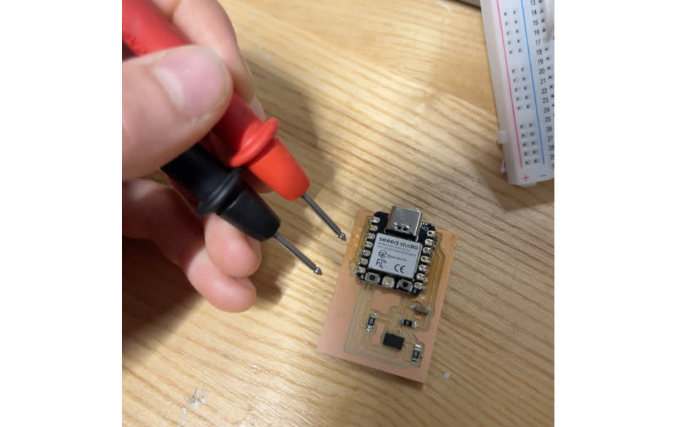
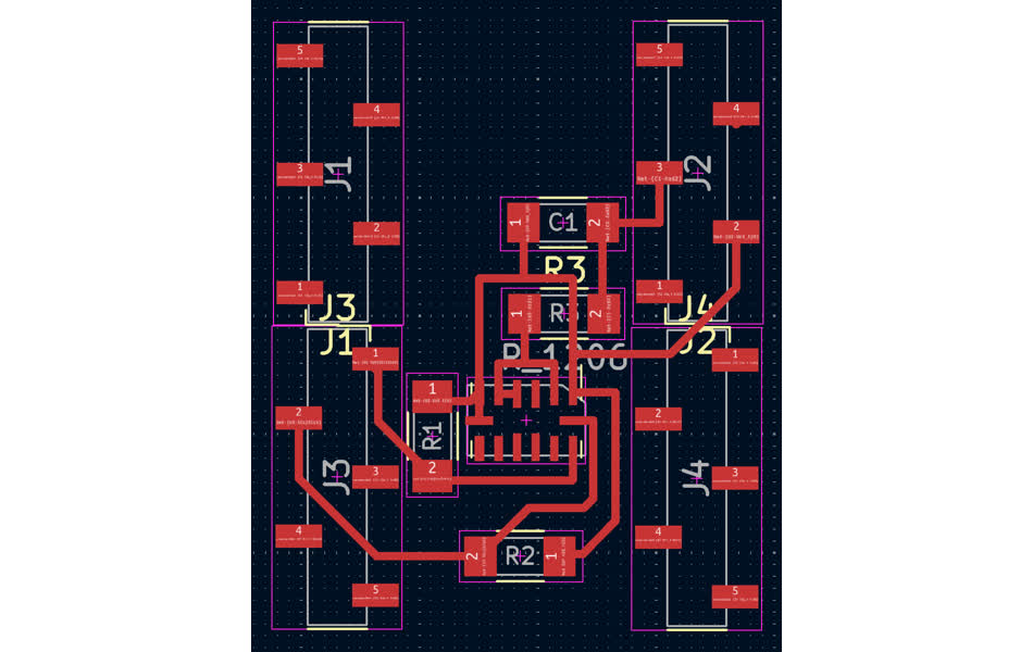
Leo suggested I separate my components onto separate boards for easier problem identification. I ran out of time for that, so I just made the schematic for it.
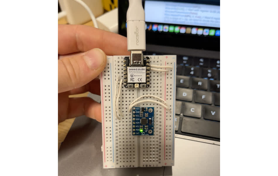
I used my remaining time to experiment with data acquisition from the MPU-6050. I connected SDA, SCL, Ground, and Power with the corresponding pin on the Xiao.
I talked to Leo about garnering sensor data, and I had 2 options: find or write an arduino code for my board, or use Niel's micropython script and run it on codewith.mu after downloading the micropython firmware on the Esp32c3.
I went with the former and found a script that worked from https://howtomechatronics.com/tutorials/arduino/arduino-and-mpu6050-accelerometer-and-gyroscope-tutorial/.
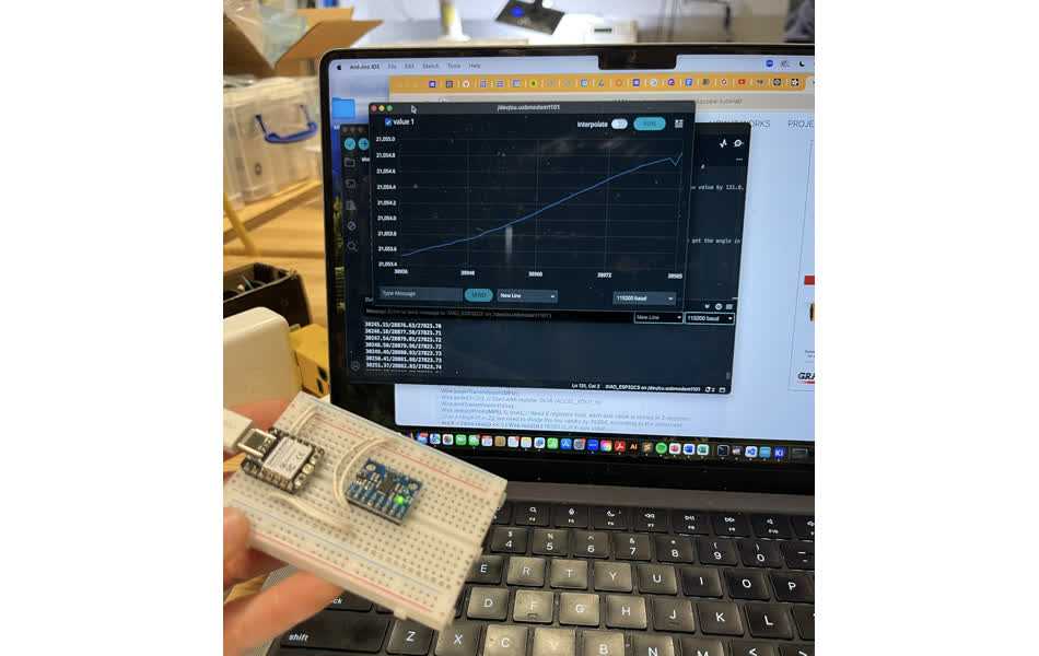
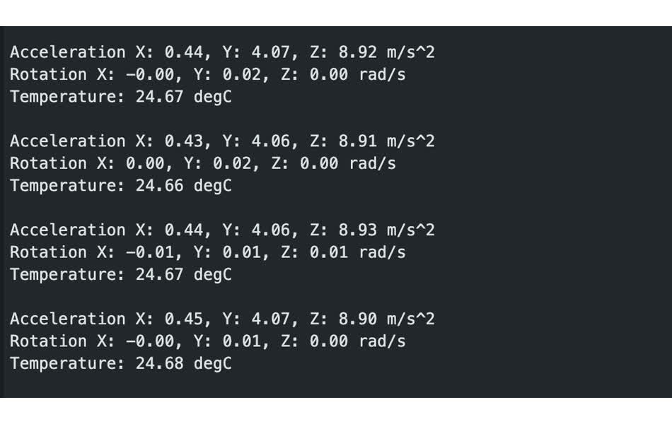
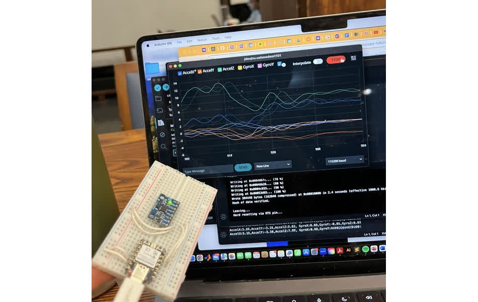
I didn't like the data display, so I looked into alternatives. I downloaded the adafruit_MPU6050 library on the arduino IDE and used the basic_readings and plotter examples. The data from both is below.
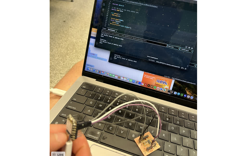
I initially could not get the accelerometer to read anything. I tried using an I2C scanner that I found here https://randomnerdtutorials.com/esp32-i2c-scanner-arduino/. The code is below.
Code Display
                                        #include <Wire.h>

                                        void setup() {
                                          Wire.begin();
                                          Serial.begin(115200);
                                          Serial.println("\nI2C Scanner");
                                        }

                                        void loop() {
                                          byte error, address;
                                          int nDevices;
                                          Serial.println("Scanning...");
                                          nDevices = 0;
                                          for(address = 1; address < 127; address++ ) {
                                            Wire.beginTransmission(address);
                                            error = Wire.endTransmission();
                                            if (error == 0) {
                                              Serial.print("I2C device found at address 0x");
                                              if (address<16) {
                                                Serial.print("0");
                                              }
                                              Serial.println(address,HEX);
                                              nDevices++;
                                            }
                                            else if (error==4) {
                                              Serial.print("Unknown error at address 0x");
                                              if (address<16) {
                                                Serial.print("0");
                                              }
                                              Serial.println(address,HEX);
                                            }
                                          }
                                          if (nDevices == 0) {
                                            Serial.println("No I2C devices found\n");
                                          }
                                          else {
                                            Serial.println("done\n");
                                          }
                                          delay(5000);
                                        }
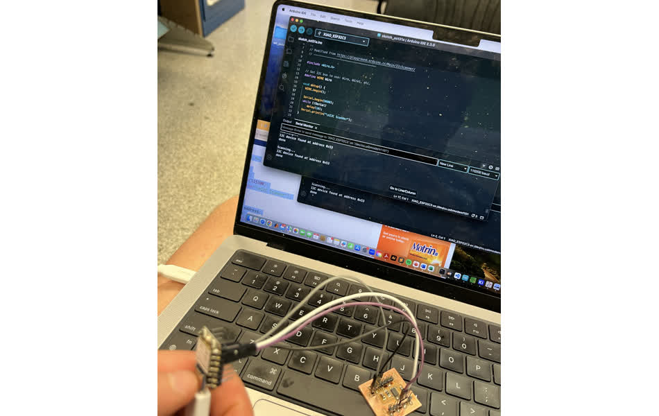
I had no luck with the scanner. I talked to Anthony, and showed him my schematic. He approved, but was skeptical of my solder work, concerned that I didn't use quite enough solder paste and that it potentially had gaps between pads and traces.
We (and by we I mean Anthony) resoldered and retried 4+ times. I lost count. (thanks Anthony) Each time, we'd run the scanner with no success.
Eventually Anthony suggested I try the scanner with a basic OLED screen. It worked. Wierd.
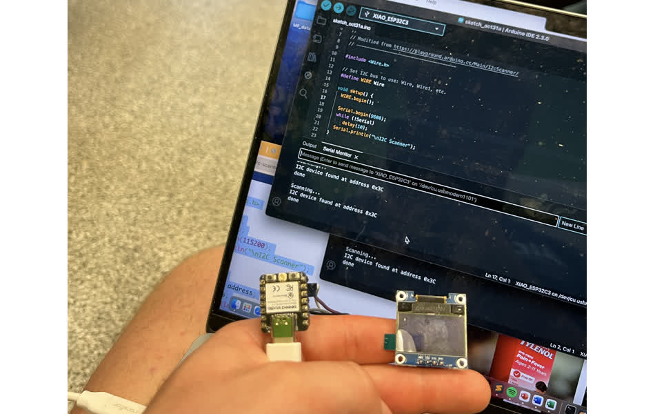
So naturally I reconnedted the ADXL 343 same as before, and it connected via I2C. Not sure what was different this time.
I re-ran the sensortest code example and it worked. Finally. I'm super happy it worked, but I'm not convinced I was doing anything wrong when it didn't work. Somewhat of an unsatisfying success.