Project 9: Output Devices
This week was all about output devices. I made a OLED display to read out ADXL 343 accelerometer data.
Let's Start with the Group Project
The group project was to probe input devices for digital and analog signals.
Making the Breakout Board
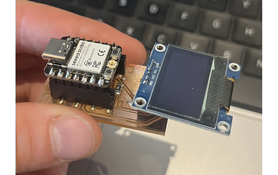
I wanted to get a SSD1306 128x32 OLED Screen to read out my accelerometer data from last week. I started by playing around with the OLED Screen.
I ensured that I had the Adafruit_SSD1306 library and Adafruit_GFX library downloaded in the Arduino IDE.
I wired the SDA, SCL, ground, and power to my ESP 32c3 and ran the example sketch from the SSD1306 library corresponding to my screen (128x32). The video below shows all of the icons flashing in succession.
#include
It worked great. Check out the video below.
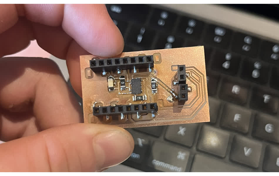
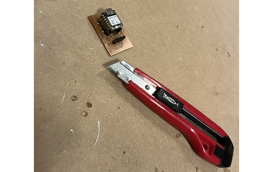
Now it was time to design my PCB. I used essentially the same design as last week's, but added some connectors for the OLED.

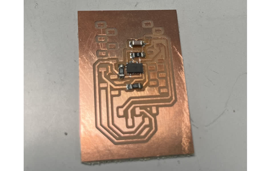
I milled out my design and soldered components. The 4 pin connector at the bottom gave my some trouble- the traces and pads started losing their adhesion and peeling up. I had to do a bit of board surgery.
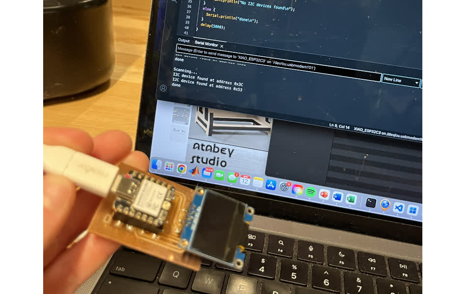
I next ran the I2C scanner from last week. This should've indicated two separate I2C connections, which I had validated with the working breadboard setup above. Unfortunately, no I2C components were found.
I removed the OLED screen and had the same result-no connected I2C devices.
I resoldered the ADXL343 with a bit more solder paste and tried again. I added all the components and tried again. Still no I2C device.
I removed the OLED to see if my accelerometer was working. The scanner found the ADXL343. The problem had to be isolated to my OLED screen.
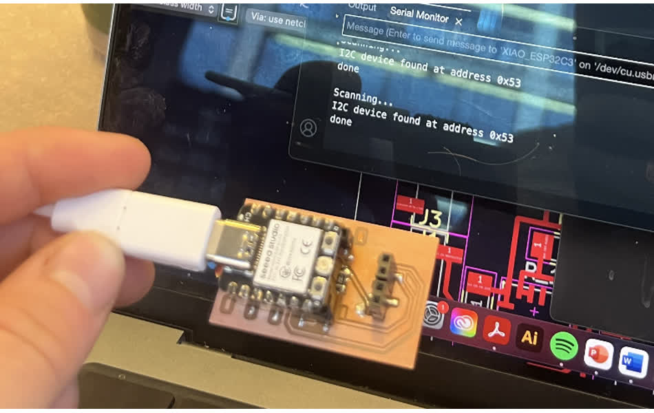
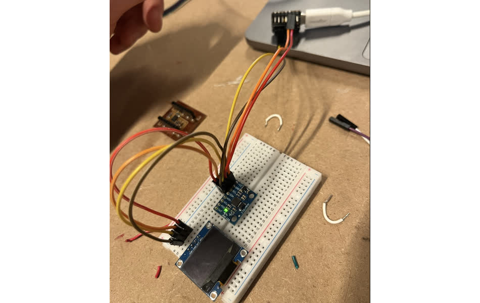
I then removed the OLED screen from the PCB and tried to use my board like a breakout board for the accelerometer. I used a breadboard to resolve traces that I no longer had.
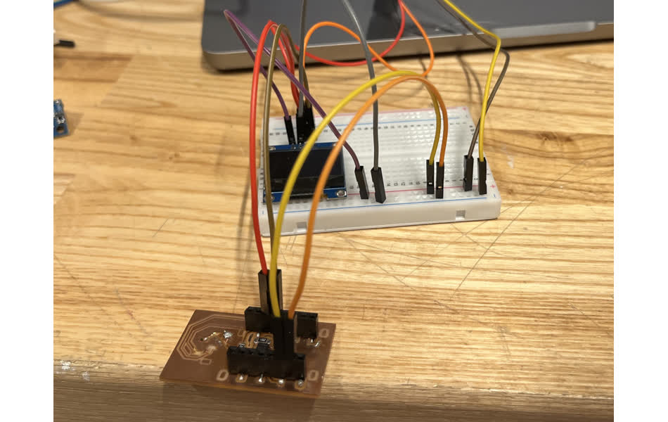
I ran the I2C scanner and it was able to find both devices. This was exciting. I wrote a script to read out the sensortest example data to the OLED screen.
This worked! I think it is because I had my traces from my OLED screen in the PCB routed to the pullup resistors from the ADXL 343, which may have interfered with things. Instead, I needed to route those traces directly to the Xiao.
#include 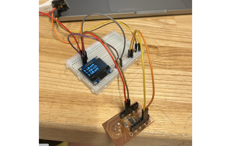
I redid my traces in KiCAD accordingly.
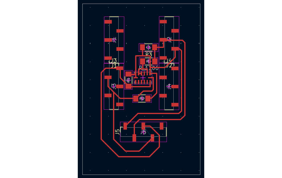
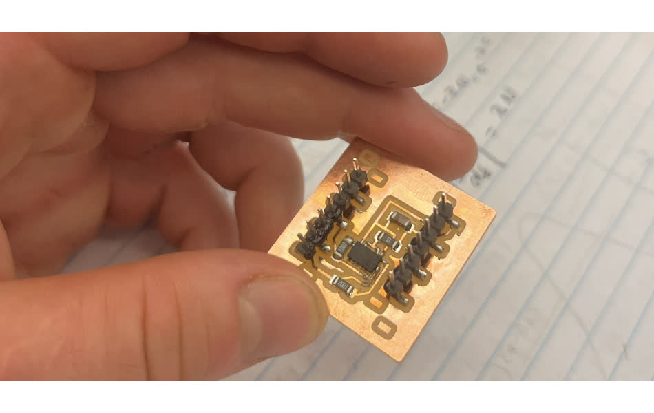
Then I re-milled my board. And soldered on the components.
First, I tried the I2C scanner. I had an issue with the OLED. The scanner only found the accelerometer, not the OLED.
With Leo's help and some multimeter use, we found that I had miswired SDA and SCL. It was time for some surgery.
I cut then crossed the SDA and SCL lines with additional wires.
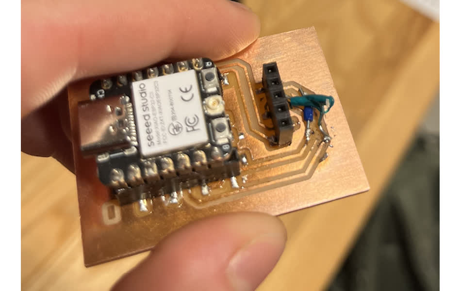
I tried the scanner and now, it was recognizing both I2C devices.
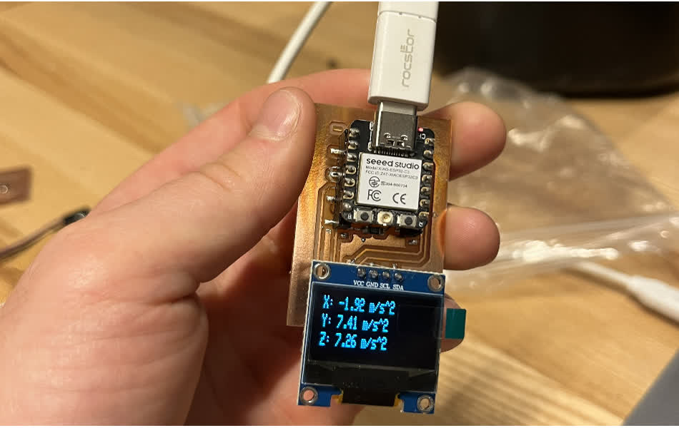
Finally, I ran my script and was able to read out my accelerometer data to the OLED.