Project 3: Embedded Programming and Electronics
This week was all about embedded programming and electronics. To start, I reviewed relevant specifications for a variety of microcontrollers. I then ran a simulation on wokwi to analyze the functionality of my script. For this project, I simulated the use of a MPU 6050 IMU to gather data and read it into a SSD1306 OLED display. I'm hoping to be able to use this for my final project. My objective is to perform modal analysis on pedicle screws, and I have to determine whether IMUs are sensitive enough to measure vibrations.
Let's Start with the Group Project
Our task this week is to demonstrate and compare the toolchains and development workflow for alternative embedded architectures. I did this assignment with Alex, Nami, and Fletcher.
Let’s start with the basics (I’m a total beginner)
What is a toolchain?
- Toolchains are tools that help you write programs and translate them into a language that a device (Arduino, Raspberry Pi e.g.) can understand.
- The toolchain helps you load the program onto the device so it can run
-The toolchain operates as follows: using a compiler to write a binary file, then a programmer to write that binary file into the microcontroller
What makes a toolchain?
- An editor - where you can write code
- A compiler - A translator which converts the code you write into code your device can understand
- An uploader - sends your code to the device
Arduino Development workflow:
- Write code in Arduino IDE: Typically written in C++
- Compile Code: This is done by the IDE to create a format the
- Upload Code: Connect the device to your computer via USB and transfer the program
- Run the program on the device: Arduino will be able to load and run the program on the device itself
- Example: A simple program instruct the Arduino to pass current to a diode when a button is pressed
Raspberry Pi Development workflow
- Write code: Various editors are available (Thonny, VS Code, Python)
- Run code: Raspberry Pi runs a full operating system (usually a Linux). Therefore you don't need to upload the code, you can just run it like a program on your computer
- Capability: Unlike Arduino, Raspberry Pi can handle more complex tasks because of its operating system
- Example: If you want to control a motor using the Pi, you write a Python script, run it directly on the Pi, and it controls the motor in real time.
Comparison between the two:
- Arduino: Simpler, perfect for smaller projects like controlling lights or sensors
- Raspberry Pi: More powerful, like a computer. Ideal for complex tasks like running a web server or controlling multiple devices at once.
What are ARM and AVR?
- These are processors inside a device that adhere to the program you write to make the device do something
AVR:
- Used in simpler devices like Arduino... They're great for simple tasks like reading a sensor turning on a light
ARM:
- These processors are used in more complex devices like smart phones and Raspberry Pi
- They can run apps, connect to the internet, and control hardware all at once
Simulated Environments:
Arduino:
- TinkerCAD
- Wokwi
- SimulIDE
Raspberry Pi:
- Raspberry Pi Desktop
- Pi VirtualBox Simulator
- Wokwi for Raspberry Pi Pico
Next, I’ll compare some of the microcontrollers that are commonly used today. I referenced the “Machines that Make” Practical Microcontroller Primer, as well as Quentin Bolsee’s documentation.
Microcontroller Comparison
| Microprocessor | Manufacturer | Type | GPIO | ADC | Prog. mem | Data mem | RAM | FCPu |
|---|---|---|---|---|---|---|---|---|
| ATmega328p | Atmel | 8-bit | 23 | 6 | 32 kb | 1024 b | 2 | 20 MHz |
| ATtiny1614 | Atmel | 8-bit | 12 | 10 | 16 kb | 256 b | 2 | 20 MHz |
| PIC32MX320F064H | Microchip | 32-bit | 53 | 16 | 64 kb | 12 kb | 16 | 80 MHz |
| SAMD11C14 | Atmel | 32-bit | 12 | 5 | 16 kb | 6 b | 4 | 48 MHz |
| ESP32 | Expressif | 32-bit | 34 | 18 | 16 kb | 4 Mb | 520 | 240 MHz |
*GPIO = General Purpose Input/Output
*ADC = Analog to Digital Converter
I’ll peruse the datasheet for the ATtiny1614 and go into more detail on its functionality.
- CPU
- AVR® CPU
- Running at up to 20 MHz
- Single-cycle I/O access
- Two-level interrupt controller
- Two-cycle hardware multiplier
- Memories
- 16 KB In-system self-programmable Flash memory
- 256 bytes EEPROM
- 2 KB SRAM
- Write/erase endurance:
- Flash 10,000 cycles
- EEPROM 100,000 cycles
- Data retention:
- 40 years at 55°C
- System
- Power-on Reset (POR)
- Single-pin Unified Program and Debug Interface (UPDI)
- Brown-out Detector (BOD)
- Clock options:
- 16/20 MHz low-power internal RC oscillator
- 32.768 kHz Ultra Low-Power (ULP) internal RC oscillator
Overall, the ATtiny1614 is ideal for small, low power applications while minimizing space. This system supports programming via a single-wire Unified Program and Debug Interface (UPDI), and can be programmed with the Arduino IDE. I chose this microcontroller for simplicity.
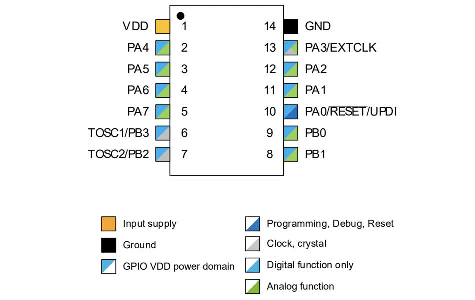
ATtiny1614 Pinout
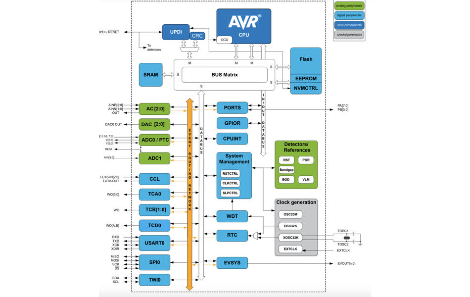
ATtiny Block Diagram
I realized that the Wokwi simulation does not have ATtiny1614 microcontrollers, so I’ll do the same for the ESP32. Overview: -designed for mobile, wearable electronics, and Internet-of-Things (IoT) applications - highly-integrated solution for Wi-Fi-and-Bluetooth IoT applications, with antenna switch, RF balun, power amplifier, low-noise receive amplifier, filters, and power management modules
Wi-Fi Key Features
- 802.11 b/g/n
- 802.11 n (2.4 GHz), up to 150 Mbps
- WMM
- TX/RX A-MPDU, RX A-MSDU
- Immediate Block ACK
- Defragmentation
BT Key Features
- Compliant with Bluetooth v4.2 BR/EDR and BLE specifications
- Class-1, class-2, and class-3 transmitter without external power amplifier
- Enhanced Power Control
- +12 dBm transmitting power
- NZIF receiver with –97 dBm BLE sensitivity
- Adaptive Frequency Hopping (AFH)
CPU and Memory
- 448 KB ROM
- 520 KB SRAM
- 16 KB SRAM in RTC
Clocks and Timers
- Internal 8 MHz oscillator with calibration
- Internal RC oscillator with calibration
- External 2 MHz ~ 60 MHz crystal oscillator (40 MHz only for Wi-Fi/BT functionality)
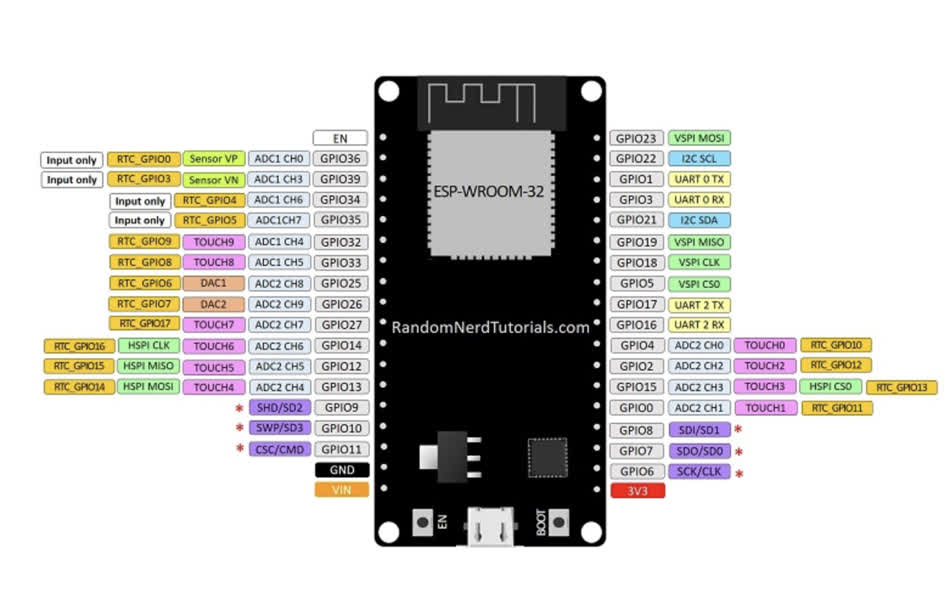
ESP32 Pinout
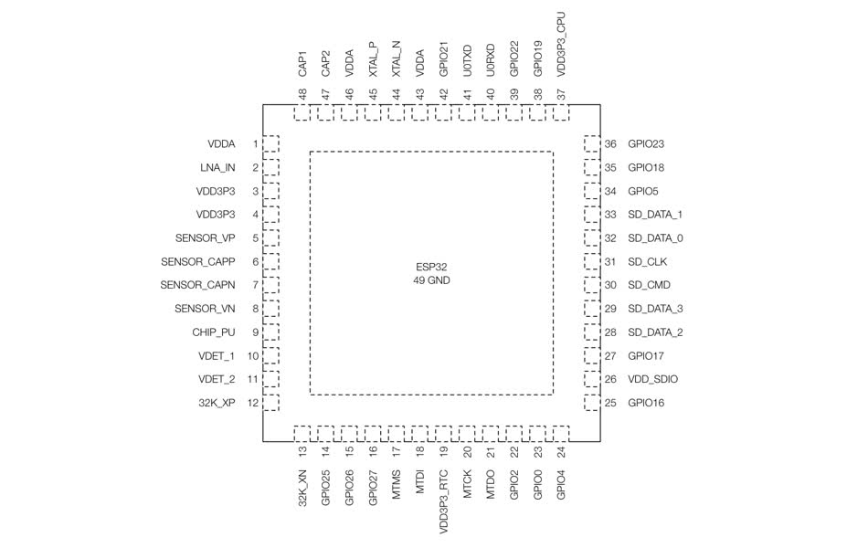
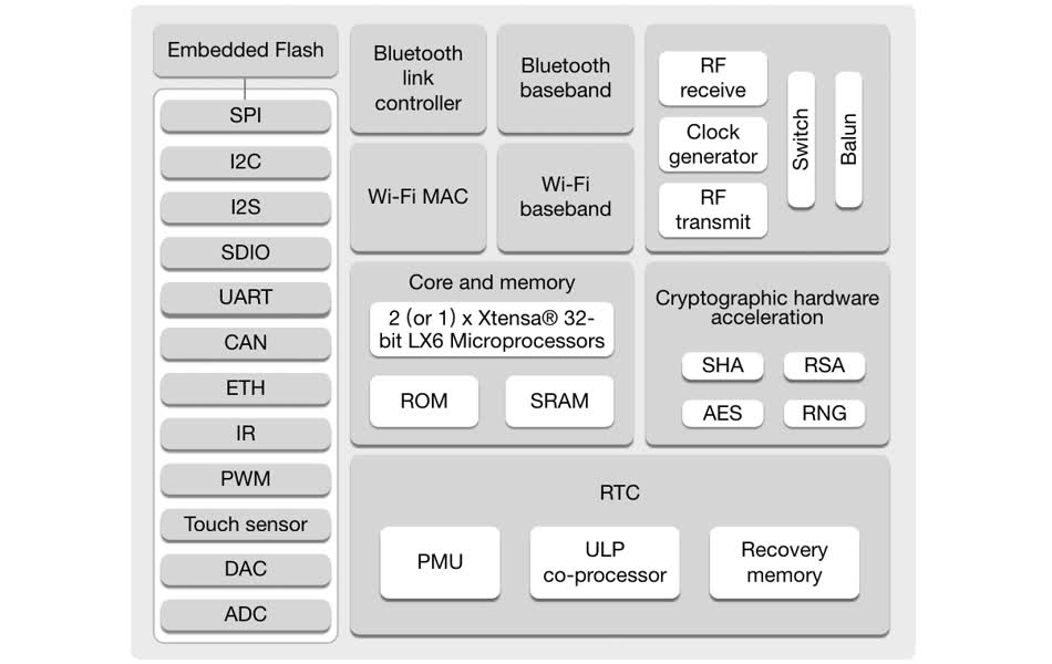
ESP32 Block Diagram
ESP32 Pin Layout
ESP 32 Embedded Programming (Wokwi Simulation)
For my individual project, I used an ESP32, which is detailed above. Initially, I wanted to use ESP32 wifi capabilities to read accelerometer data to my phone, but this was not possible in the simulation without the hardware.I simulated data aquisition from a MPU6050 accelerometer, first to the serial monitor. Watch the video below to see its functionality.
Next, I used an OLED screen to display my data. See the below video.
Here's the code I used for this project. I was able to do the serial monitor readout simulation with arduino code. I ran into some issues with identifying the OLED screen in arduino code, so I switched to micropython. I relied on a variety of youtube tutorials and chatGPT to make this script.
Accelerometer Data Serial Monitor Readout Script
    #include
    #include
    #include

    // Create an instance of the MPU6050 class
    Adafruit_MPU6050 mpu;

    void setup() {
        Serial.begin(115200);
        while (!Serial) delay(10); // Wait for Serial to be ready

        // Initialize I2C communication
        if (!mpu.begin()) {
        Serial.println("Failed to find MPU6050 chip");
        while (1) {
            delay(10);
        }
        }

        Serial.println("MPU6050 Found!");

        // Set accelerometer range
        mpu.setAccelerometerRange(MPU6050_RANGE_8_G);
        // Set gyroscope range
        mpu.setGyroRange(MPU6050_RANGE_500_DEG);
        // Set the filter bandwidth
        mpu.setFilterBandwidth(MPU6050_BAND_21_HZ);

        delay(100);
    }

    void loop() {
        // Create variables to hold sensor events
        sensors_event_t a, g, temp;
        mpu.getEvent(&a, &g, &temp);

        // Print accelerometer data
        Serial.print("Accel X: "); Serial.print(a.acceleration.x);
        Serial.print(", Y: "); Serial.print(a.acceleration.y);
        Serial.print(", Z: "); Serial.println(a.acceleration.z);

        // Print gyroscope data
        Serial.print("Gyro X: "); Serial.print(g.gyro.x);
        Serial.print(", Y: "); Serial.print(g.gyro.y);
        Serial.print(", Z: "); Serial.println(g.gyro.z);

        // Print temperature data
        Serial.print("Temperature: "); Serial.print(temp.temperature);
        Serial.println(" *C");

        delay(1000);  // Wait 1 second before next reading
        }
Accelerometer Data OLED Screen Readout Script
        from machine import Pin, I2C
        import ssd1306
        import time

        # I2C pin assignment for ESP32
        i2c = I2C(0, scl=Pin(22), sda=Pin(21))

        # Initialize the OLED display
        oled_width = 128
        oled_height = 64
        oled = ssd1306.SSD1306_I2C(oled_width, oled_height, i2c)

        # MPU6050 I2C address
        MPU6050_ADDR = 0x68

        # MPU6050 register addresses
        PWR_MGMT_1 = 0x6B
        ACCEL_XOUT_H = 0x3B

        # Initialize MPU6050
        def init_mpu6050():
            i2c.writeto(MPU6050_ADDR, bytes([PWR_MGMT_1, 0]))  # Wake up the MPU6050

        def read_accel_data():
            data = i2c.readfrom_mem(MPU6050_ADDR, ACCEL_XOUT_H, 6)
            accel_x = (data[0] << 8 | data[1]) / 16384.0  # Convert to g
            accel_y = (data[2] << 8 | data[3]) / 16384.0  # Convert to g
            accel_z = (data[4] << 8 | data[5]) / 16384.0  # Convert to g
            return accel_x, accel_y, accel_z

        # Initialize the MPU6050
        init_mpu6050()

        # Function to read and display accelerometer data
        def display_data():
            # Clear the OLED display
            oled.fill(0)

            # Read accelerometer data
            accel_x, accel_y, accel_z = read_accel_data()

            # Display accelerometer data on OLED
            oled.text('Accel X: {:.2f}'.format(accel_x), 0, 0)
            oled.text('Accel Y: {:.2f}'.format(accel_y), 0, 10)
            oled.text('Accel Z: {:.2f}'.format(accel_z), 0, 20)

            # Show the updated display
            oled.show()

        while True:
        display_data()
        time.sleep(1)  # Update every second
Heres's all my files for this week Week 3 Files