Output Devices: Stepper Motor (and Speaker)
Choosing the right Output Device
For this week, I was working toward my final project's actuation device. In sum, I wanted to imitate a rotating kitchen oven timer that is programmed to move as it counts down time but can also be manually reset to allow for more time. I discussed some possibilities with our TA this week, a great resources, Will Langford. Below are some key learnings about the different motors:
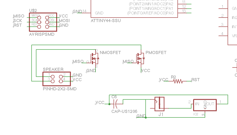
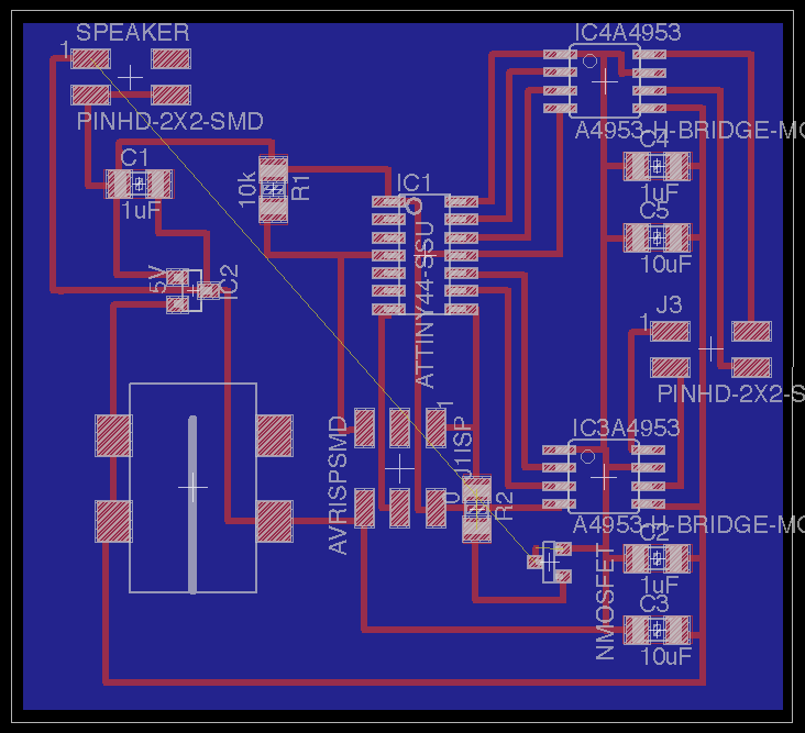
Board Design
Fabduino Attempt
Main lesson this week: Shortcuts often cost you even more time.
I wanted to begin work on my fabduino in preparation for Network and Communicaitons week so I could have a board that was ready to interface with my wifi module/shield. I began by downloading the fabduino fabkit board and schematic so I could jump ahead and focus on my edits (adding a speaker, motor, and potentially an LCD screen).
I downloaded the files and began adding all my parts.
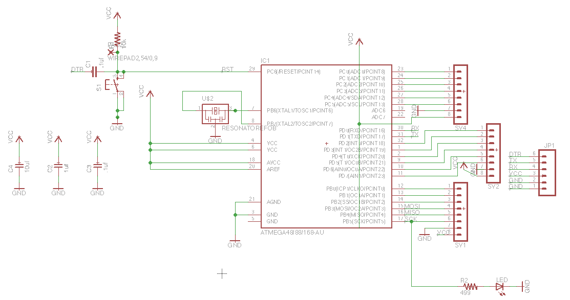
Original:
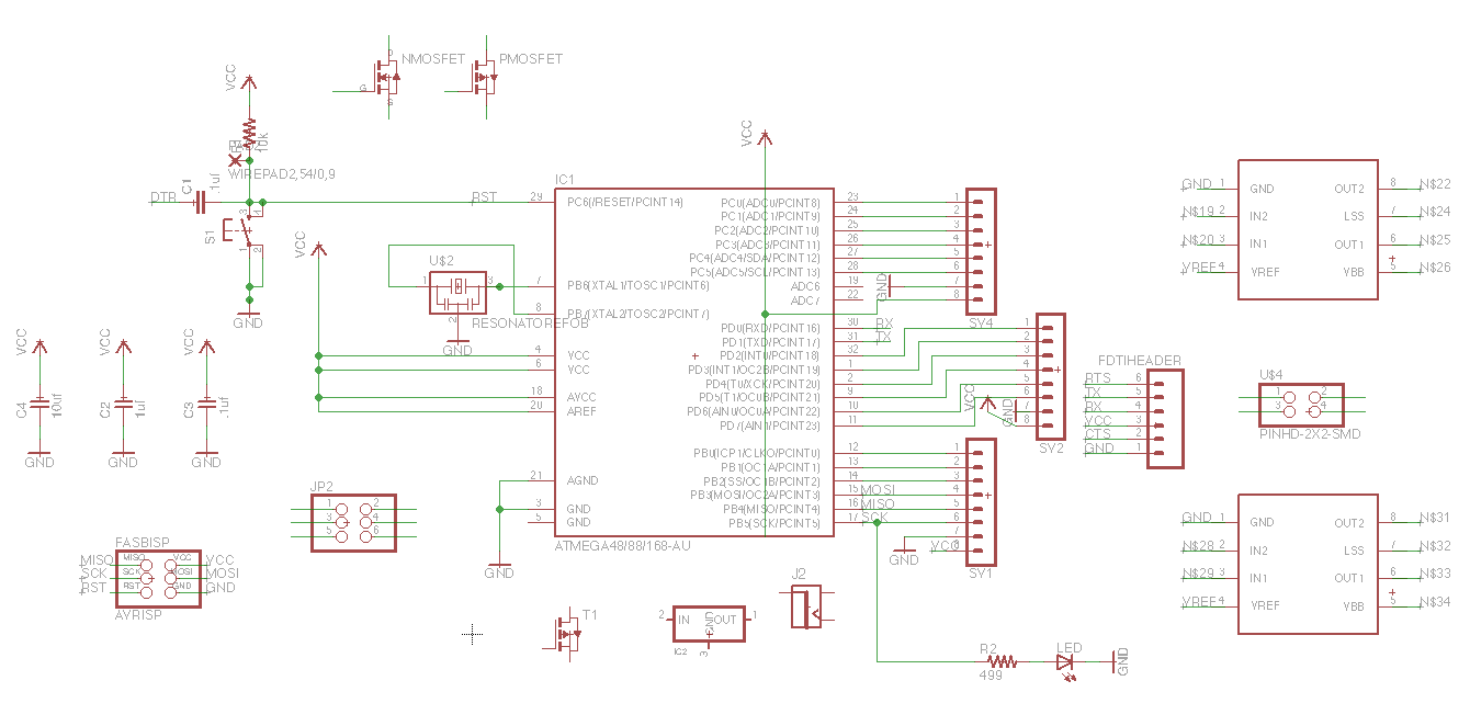
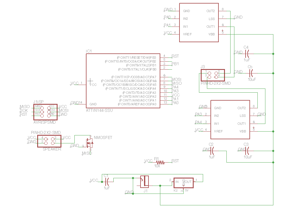
With my edits:
And after all my work I didn't realize the files were broken and not communicating to each other, as in, the add-ons in the schematic were not transferring to the board.
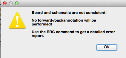
We think the problem comes from downloading a schematic and board that is not saved in a zip file, together. Also, in Eagle your file name is hardcoded into the file so when you change the name of a file, it breaks (similar to Solidworks). In general, even when copying a design it's valuable to get the muscle memory exercise of practicing your own netting and routing. So that's when I restarted...
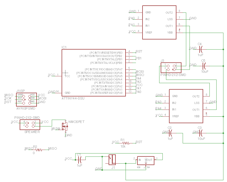
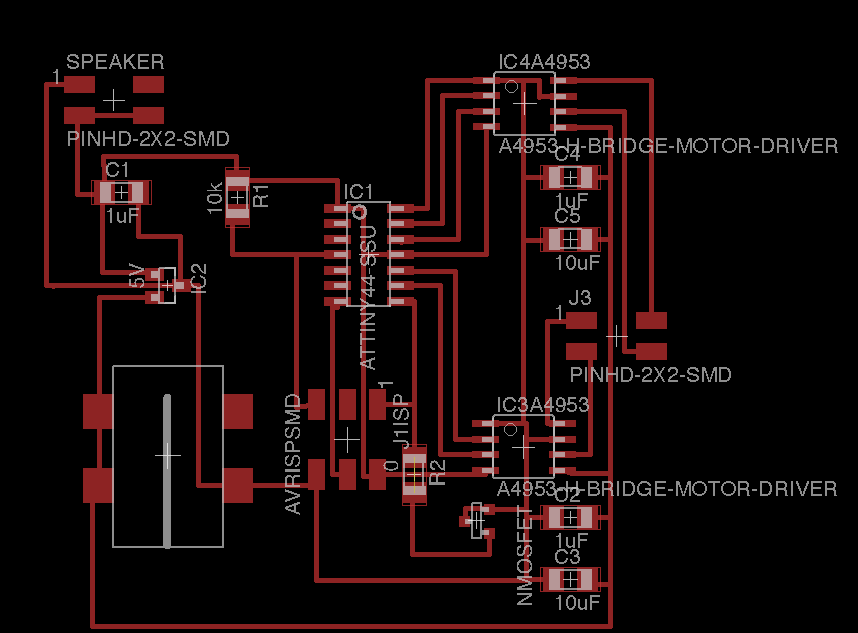
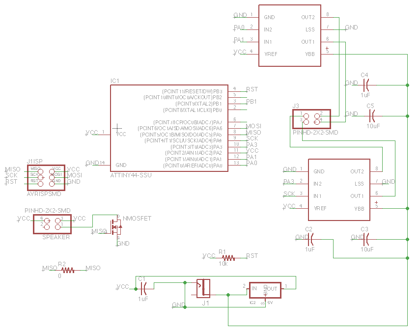
Stepper Motor and Speaker Success
Routing is fun and a good skill. Enjoy it while you can.
It's always good to get feedback from your mentors as you go, and not wait until the very end.
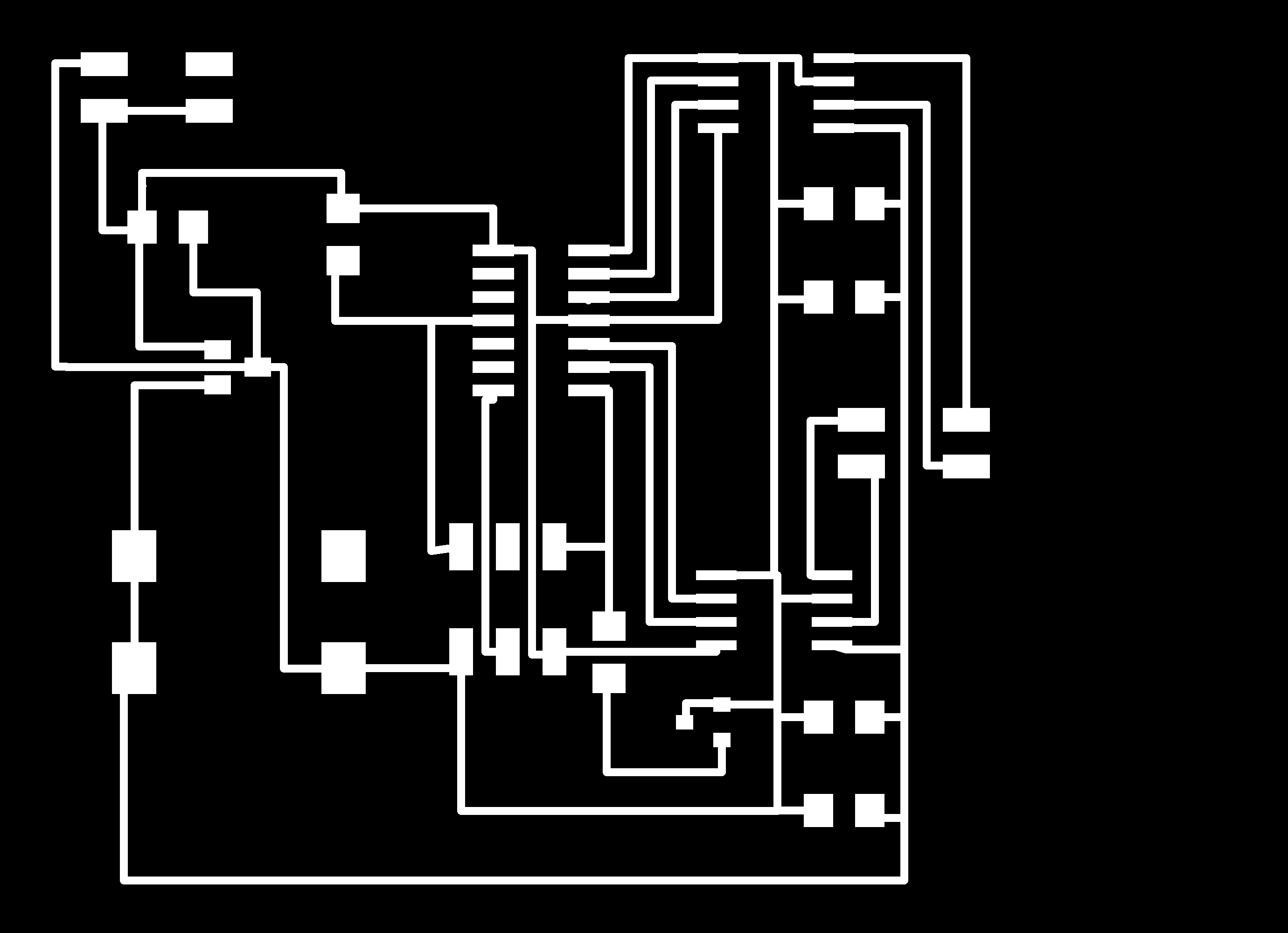
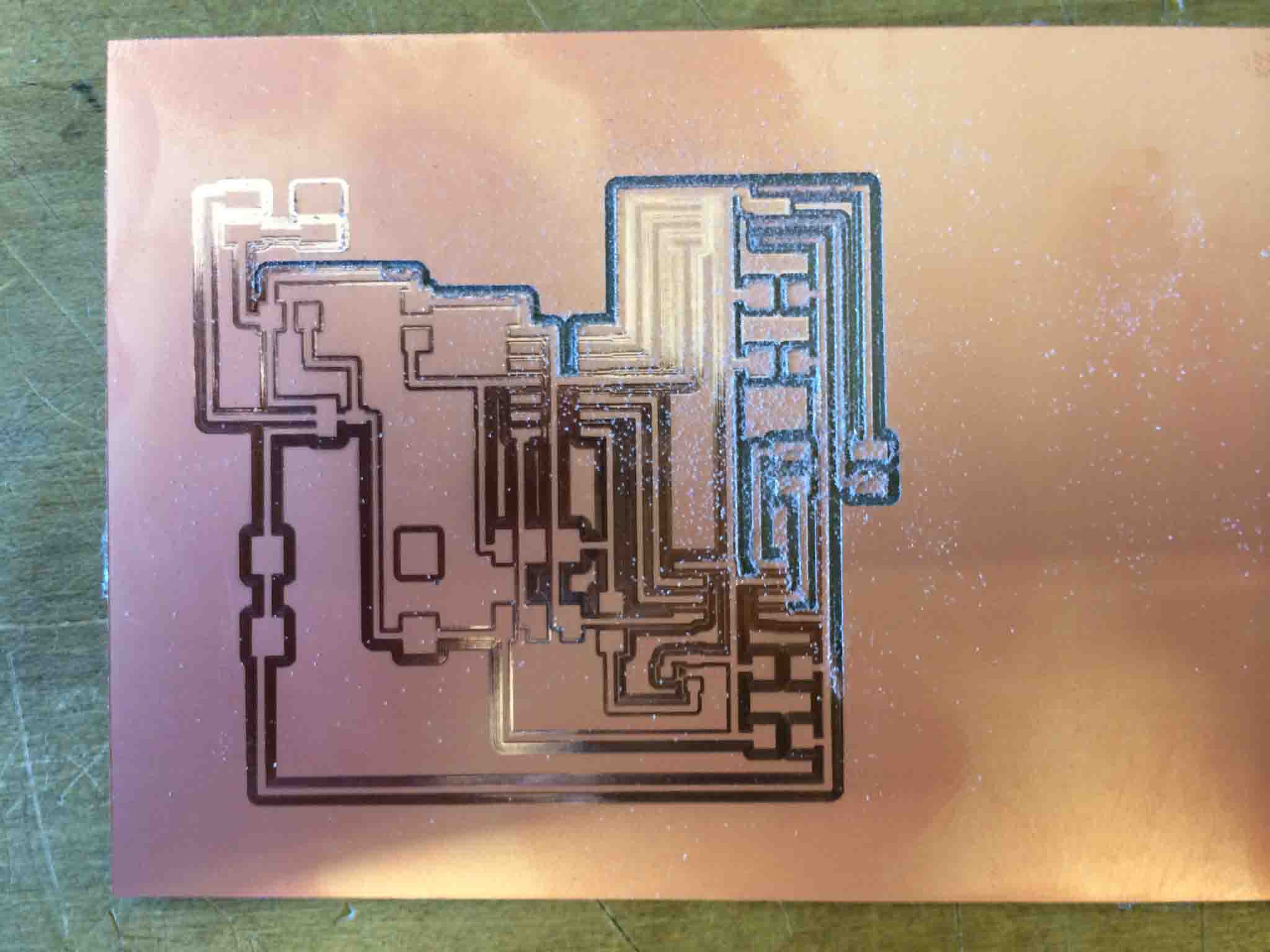
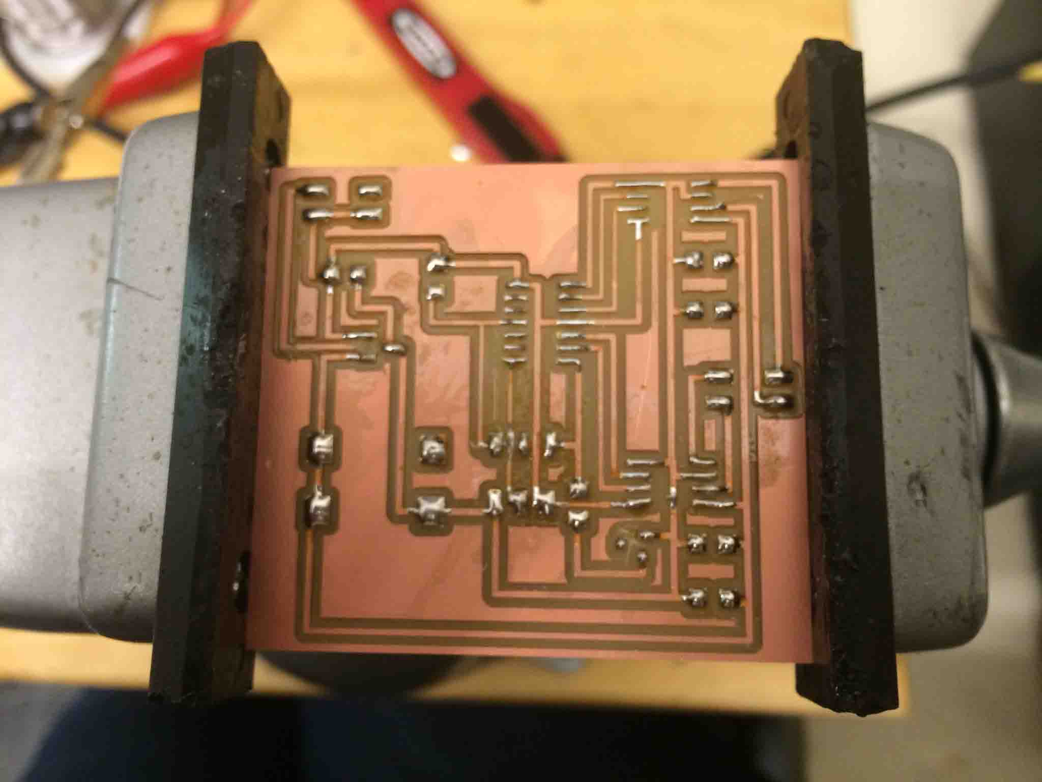
Milling and Stuffing the PCB
Ready to mill and upload in the Roland Modela (rml).

Cut depth default is .1, but the modela is a bit old, need to change this to .25, else the area outside the traces (the copper removed) is not entirely removed and remains too shiny. This leaves a risk of shorting your board with unintended connections!
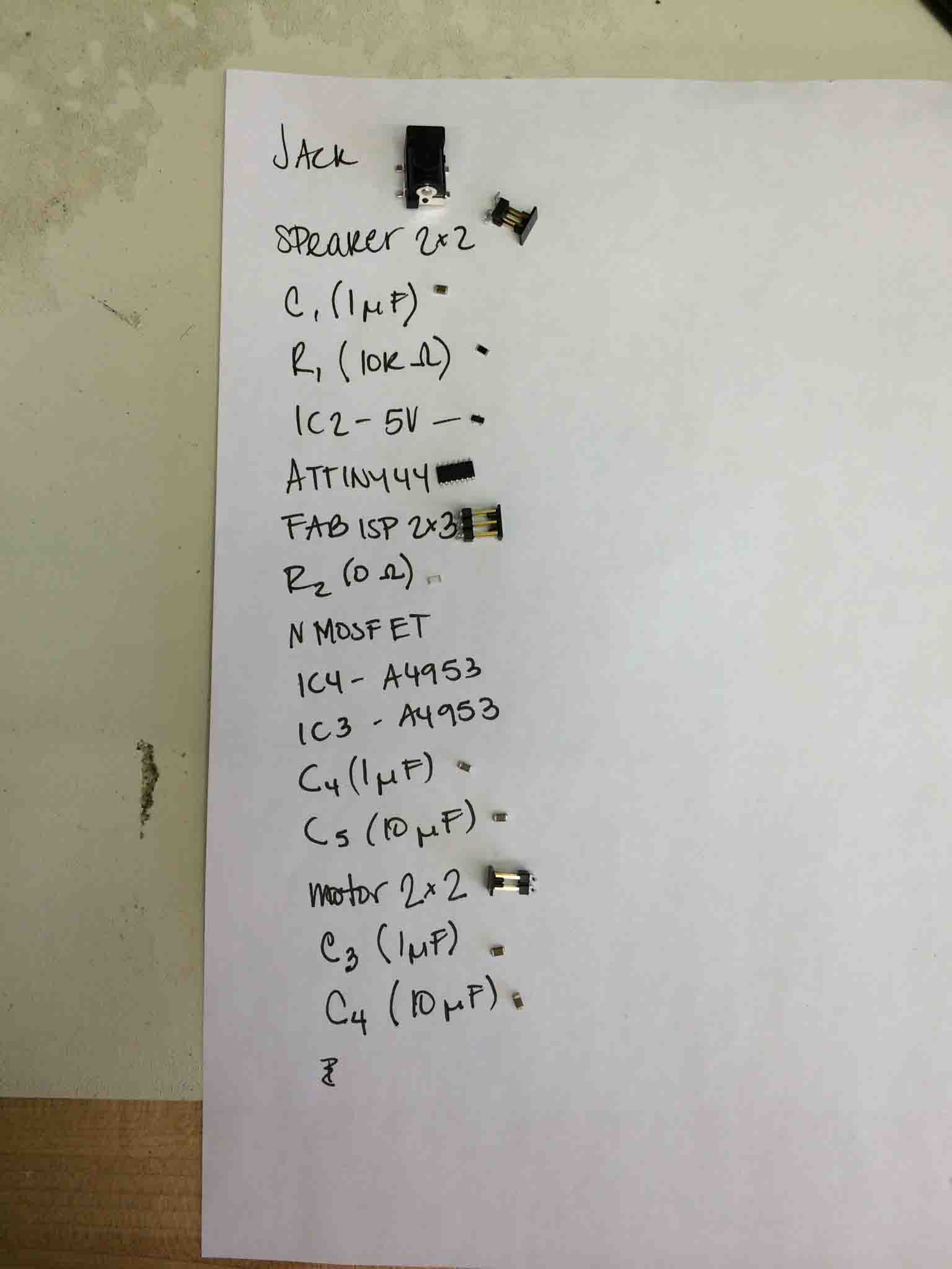
Organized inventory of your components is a great, underrated (though tedious) skill.
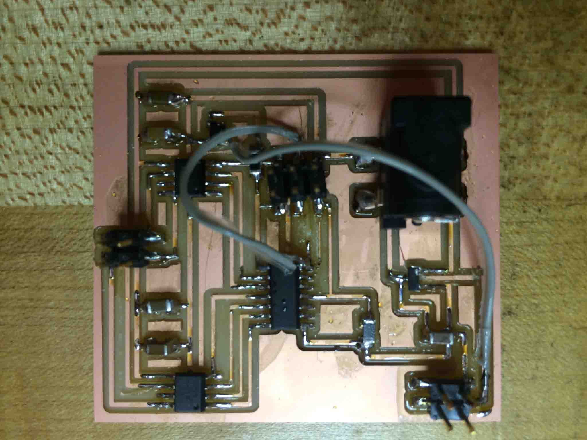
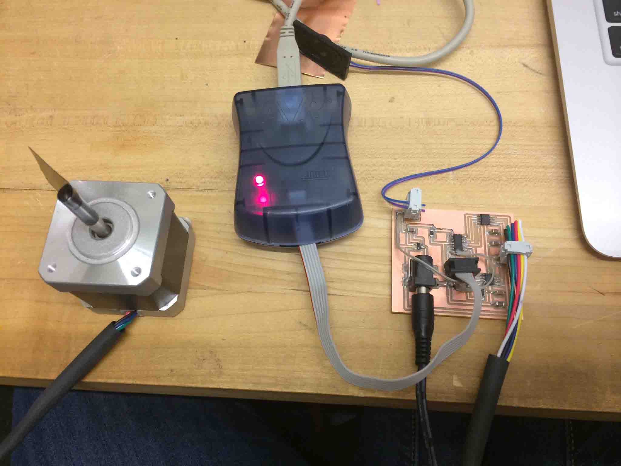
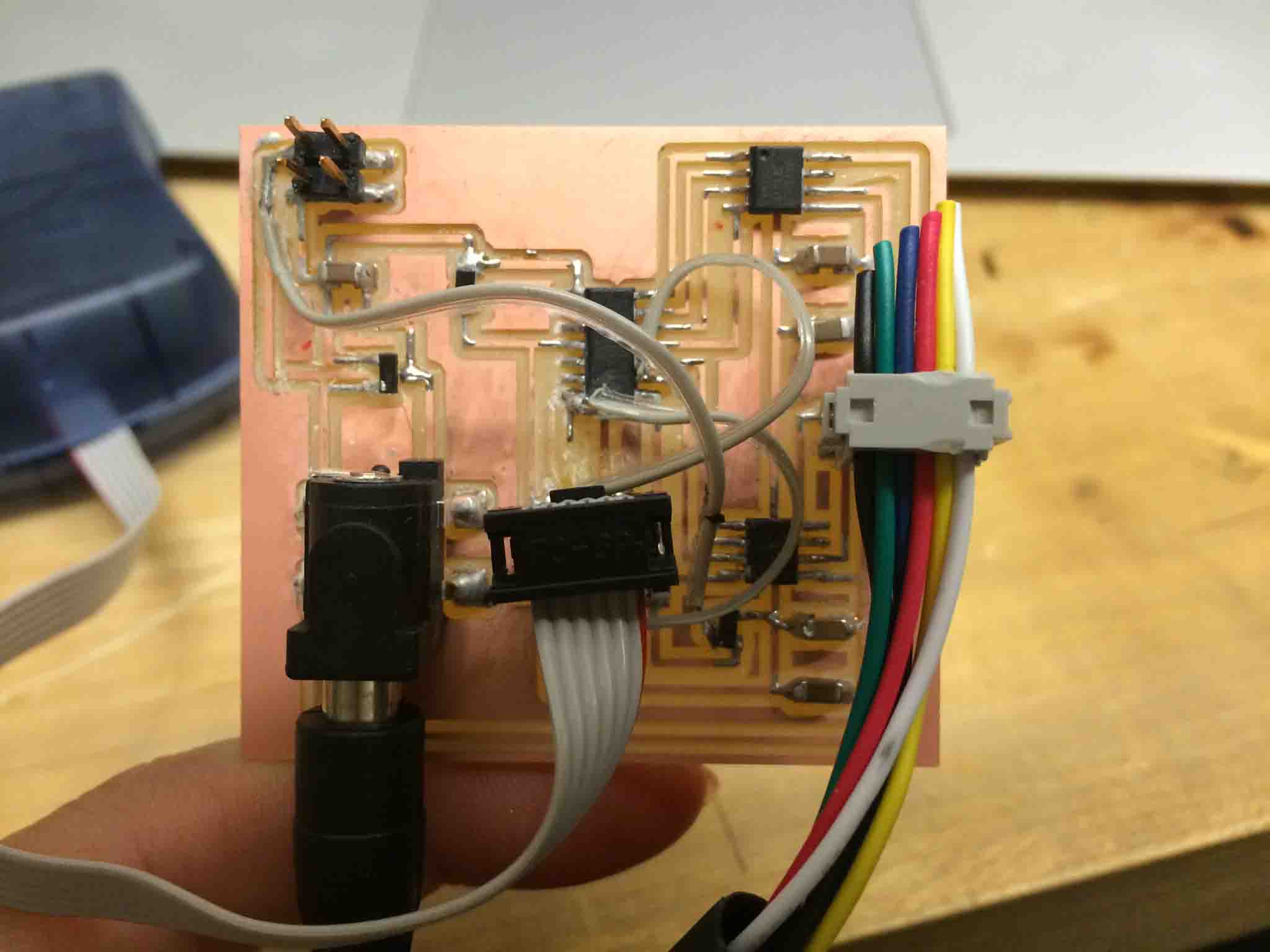
At this point I got an email from Will saying my MOSFET was incorrectly connected, so I edited it in Eagle, but rather than re-mill my board, I cut off the incorrect traces with an exacto knife and made some connections with wire.
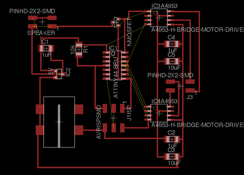
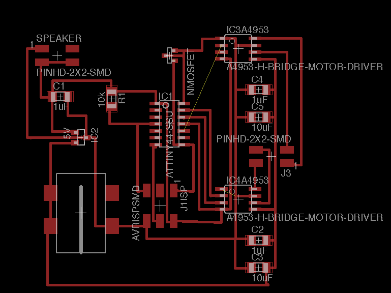
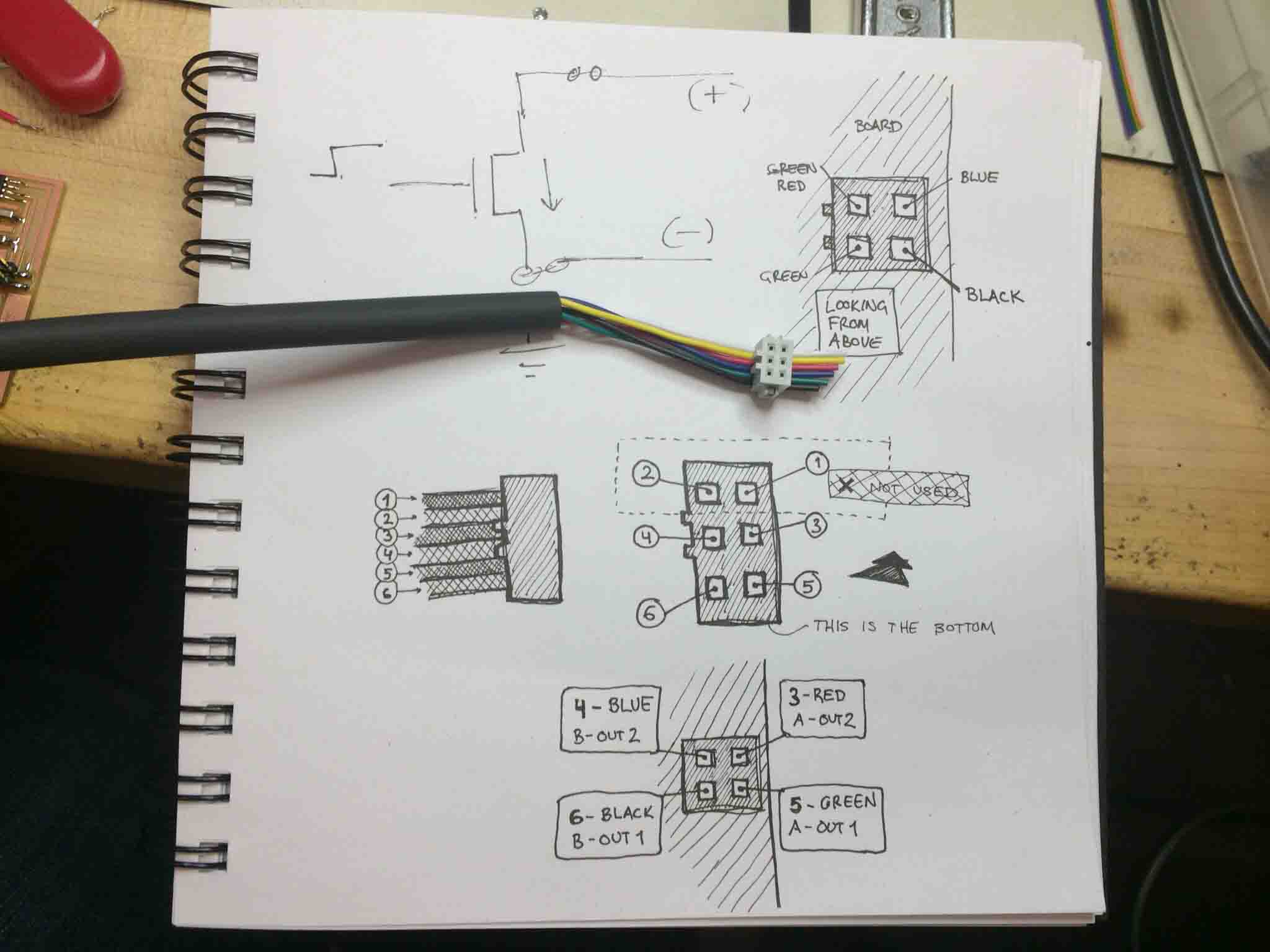
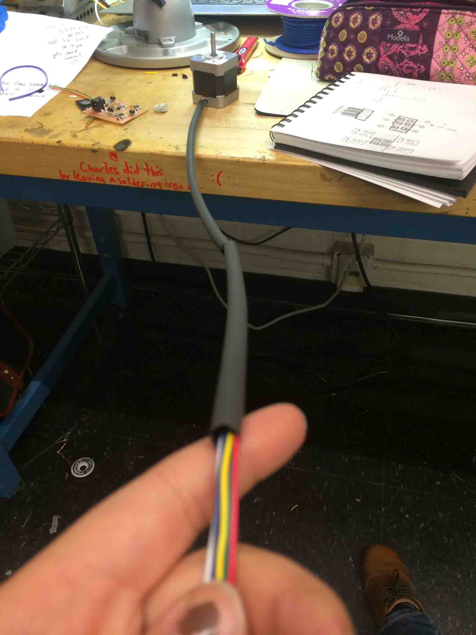
I had to make my own cables to connect my devices (stepper motor and speaker) to my board. For the Stepper motor, it's important to note the pairs of cables that have to connect, each to it's own bridge. Using the diagram below (thanks for the drawings, Anders!) the pair of green and black will connect to my IC3 (A4953 H-Bridge) on the bottom of my board. and the pair of red and blue will connect to my IC4 (A4953 H-Bridge) on the top of my board.
Heat shrinking cables are nice because they make you look organized and tidy. I just didn't have the patience to let it heat and shrink, so I'll make that prettier later =).
The issue became that my end mill on the model (1/64) was too big for some of the spacing I had left aorund the FabISP and I was scared of shoring. To hackily fix this, I cut some of the traces and replaced the connections by soldering wire to it. You can just strip off one wire from the ribbon cable use the wire strippers to remove the plastic shell off the tip and expose the wire underneath.
Programming and Debugging
Now for the moment of truth. You'll see here a chronological story of how we discovered issues as we went along and the fixes for each. The biggest take-aways from debugging were:
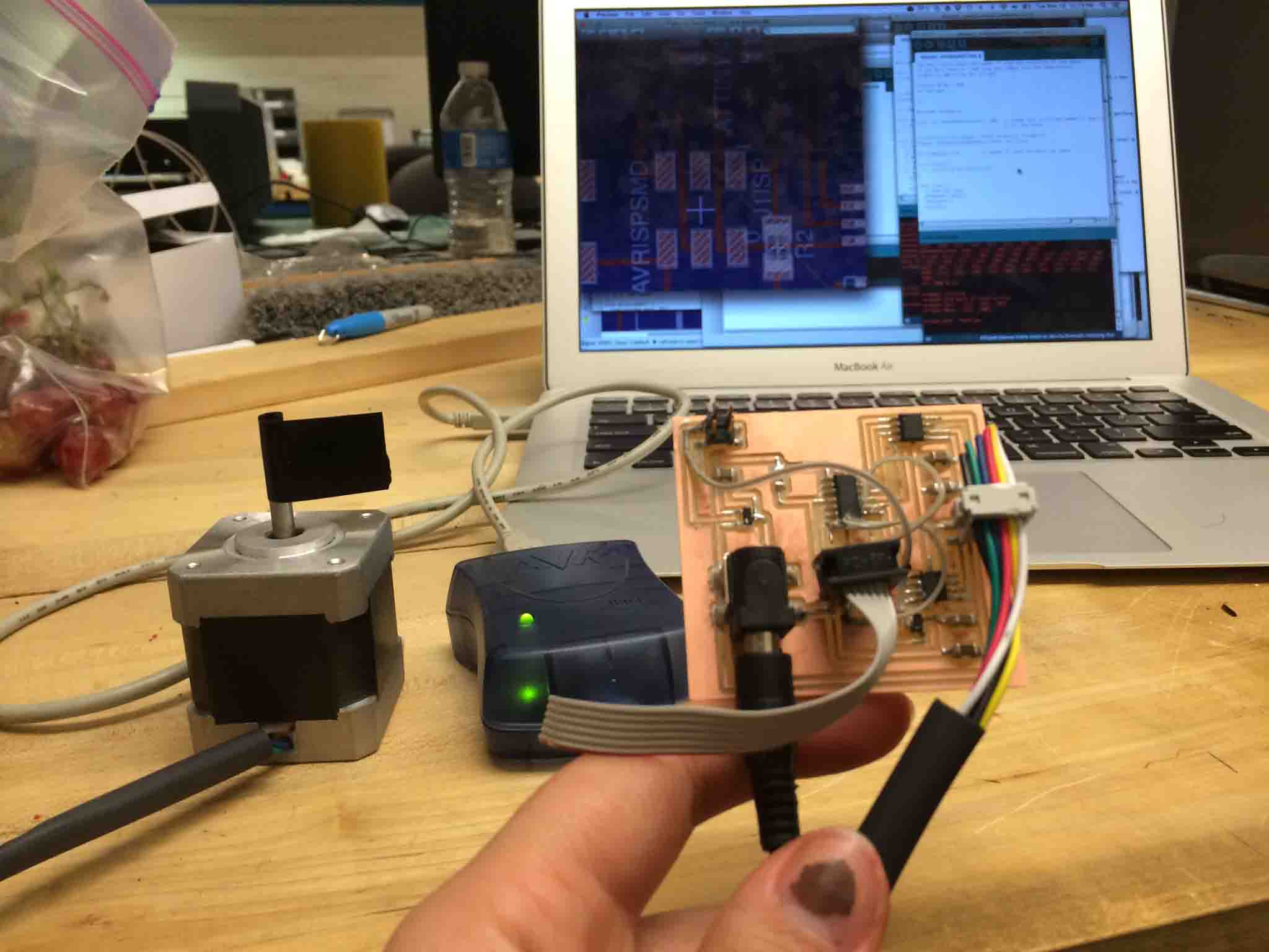
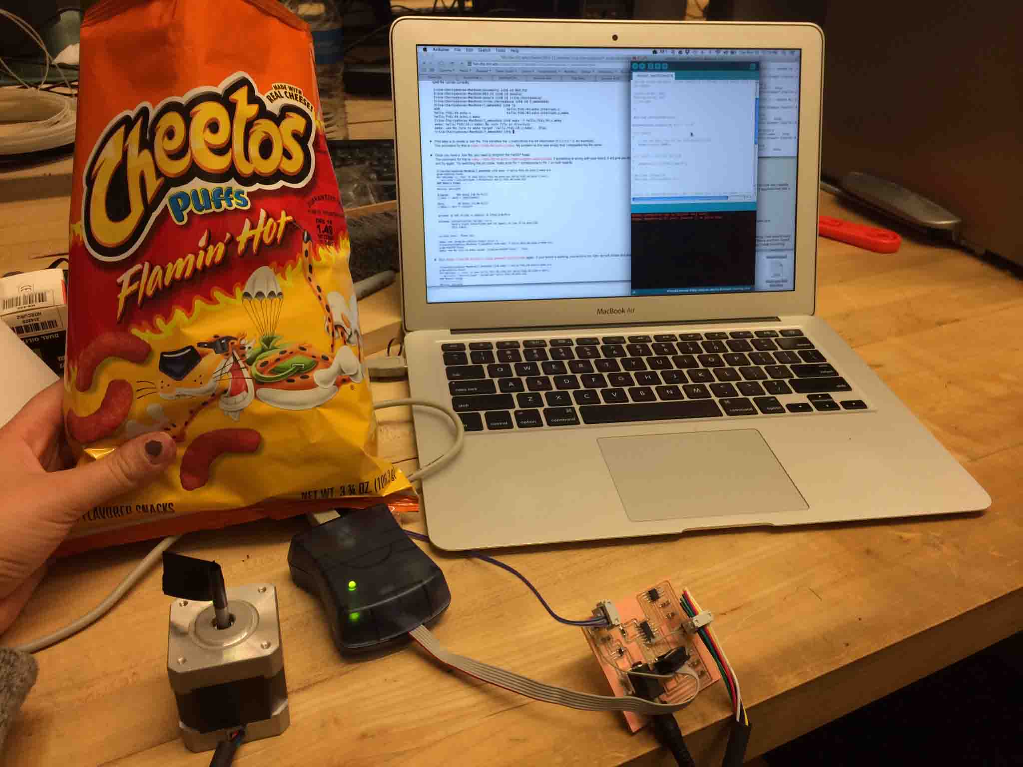
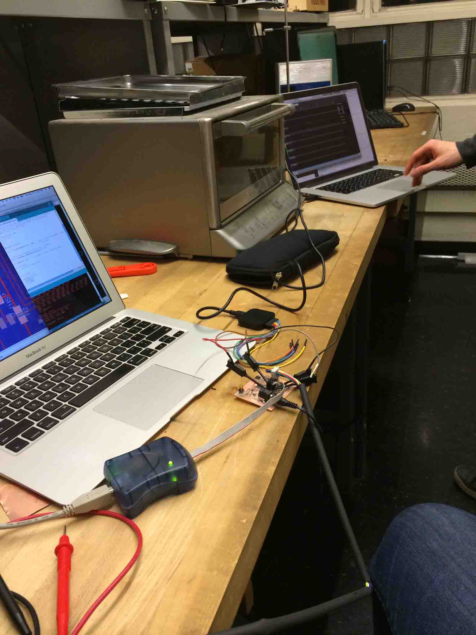
This is the part where you email the TA, bribe him with Cheetos, and try to figure out why there are false positives (green lights) on your board.
Then Will Langford showed up and we played a game of Operation by attaching the cutest mini hook jump cables to my FabISP header.
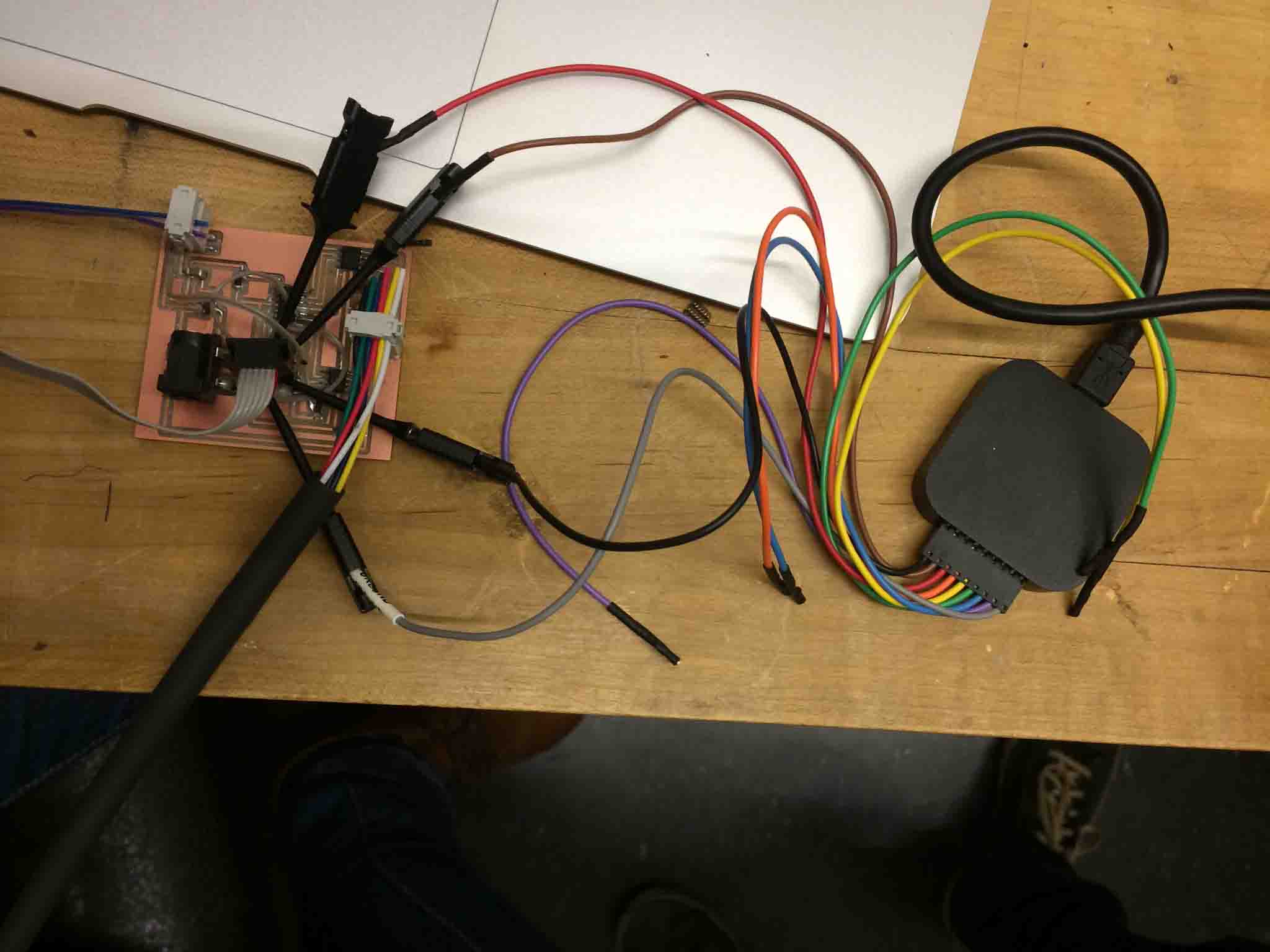
These connected to his computer's program that shows you want signal activity is being transmitted across the pins.
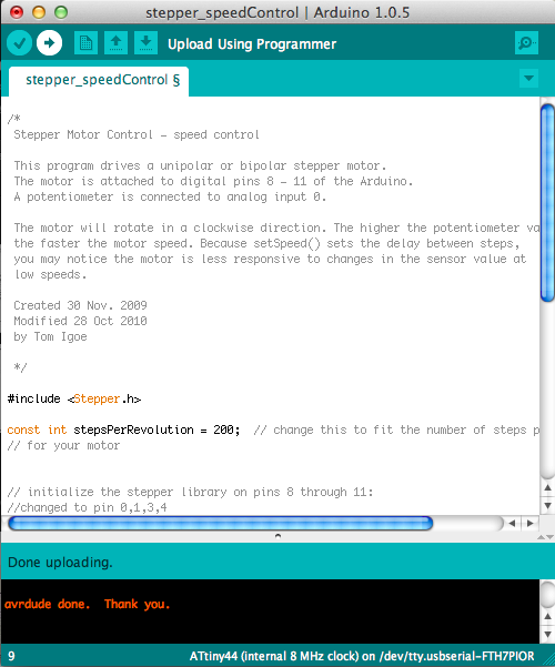
Here it is working with the default Ardunio example code.
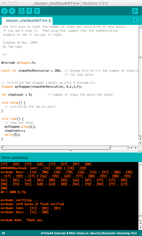
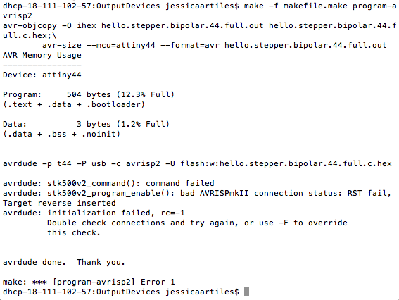
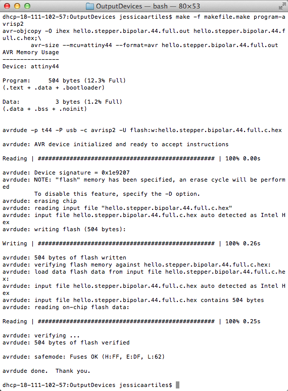
Here it is working from the terminal with C code with the default code (make sure you download the "full" link from Neil's pages.
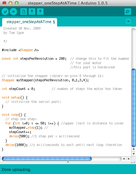
Here it is with some edits to the code, adding a for loop, to control the revolutions of the motor.
The code is in a good place and ready to match up with the outer Interface Design for the timer! Next step: Integration with speaker and input devices for the final project!