Input Devices
BIGGEST TIPS:
When designign and manufacturing your board:
When debugging your board and Arduino code:
Chronological documentation of the process
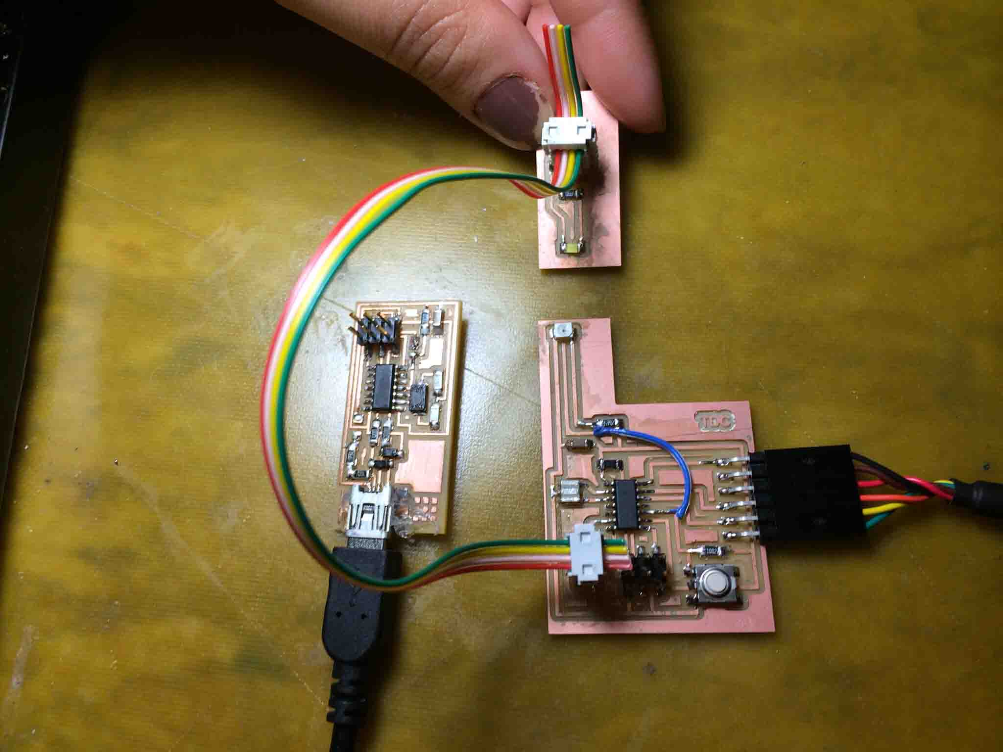
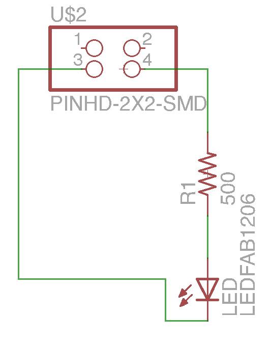
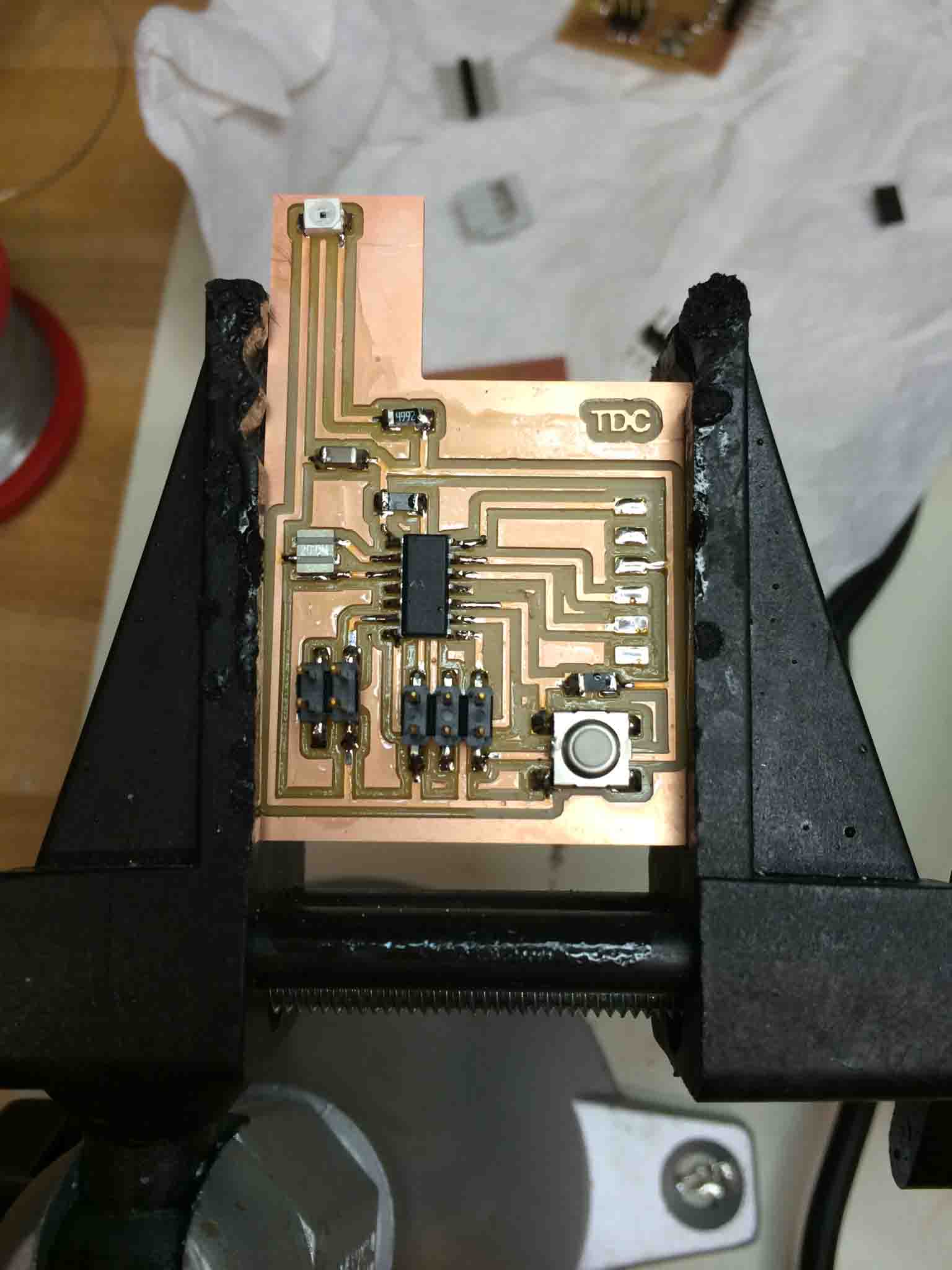
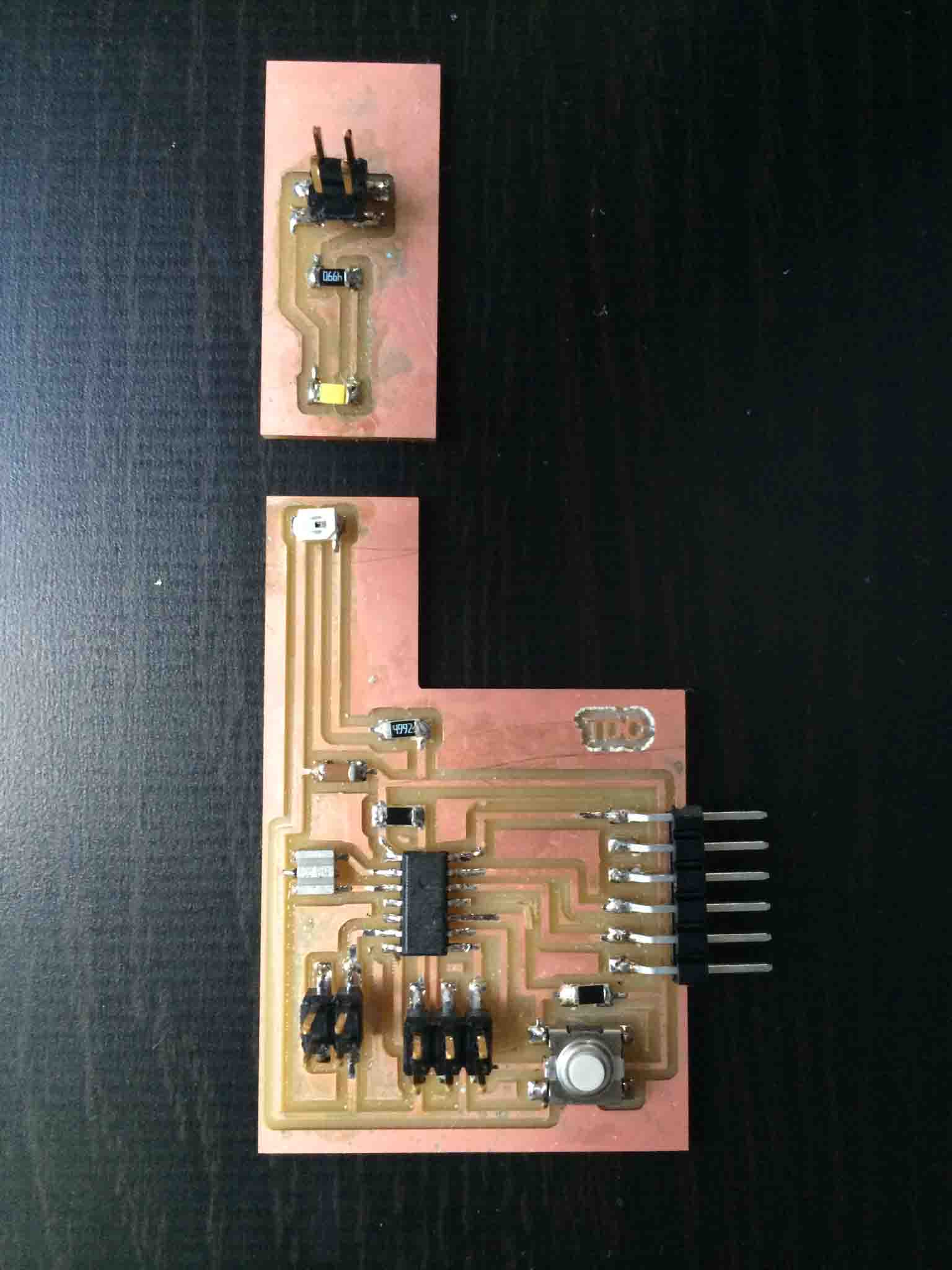
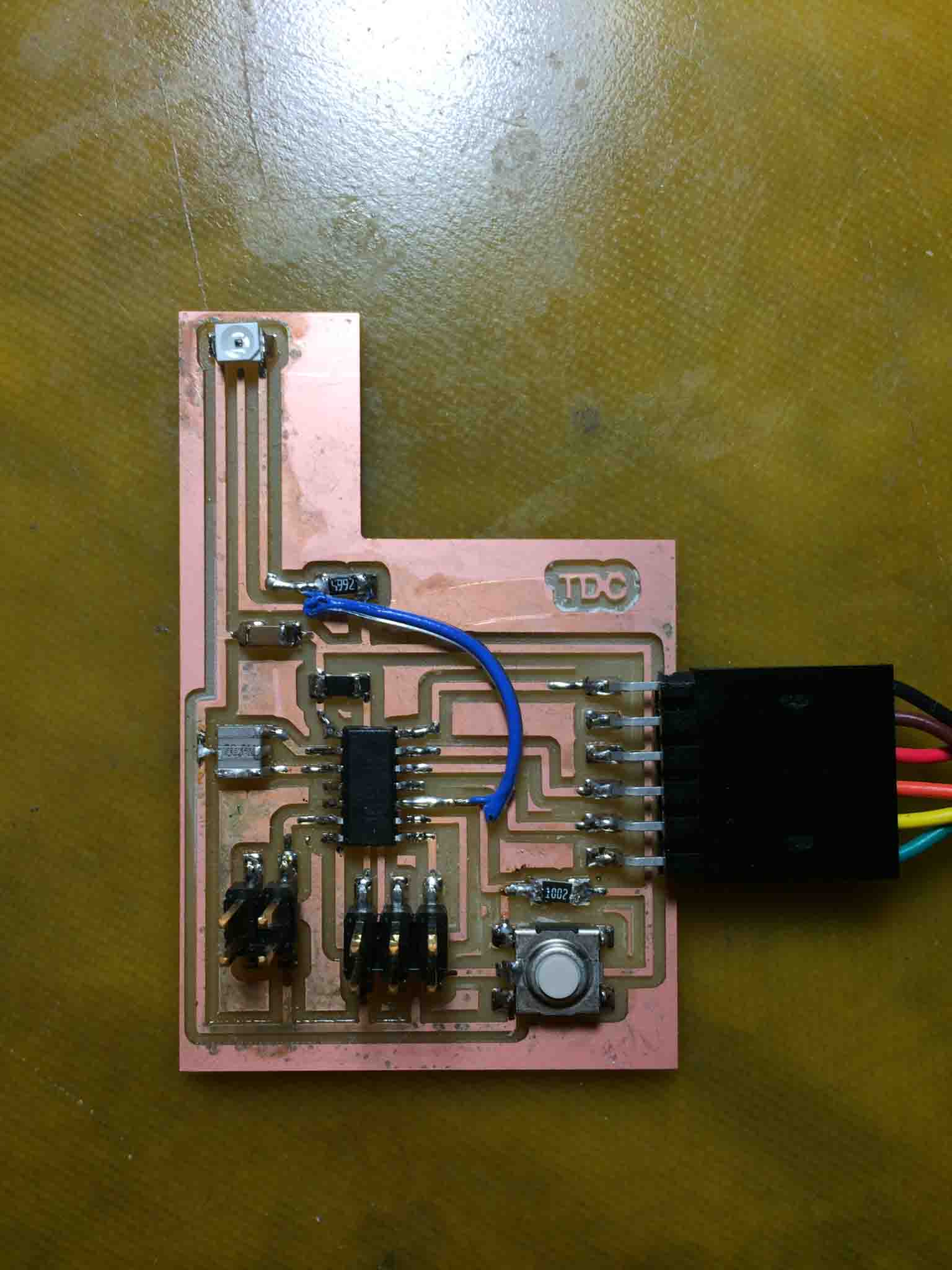
I decided to use this board towards my final project and decided the best way to count the dials on the rotary lever would be to wire a PhotoTransistor to an LED light that would be permanently on. I used the board from Embedded Programming week, removed the LED and corresponding resistor to an addendum board that would be powered through a 2x2-pin header, and added a phototransistor to the main board.
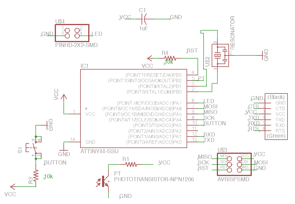
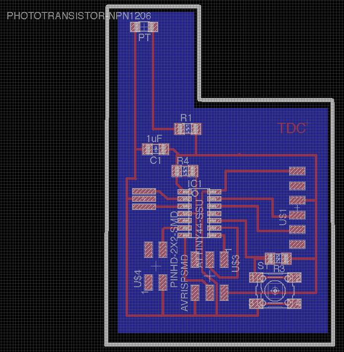
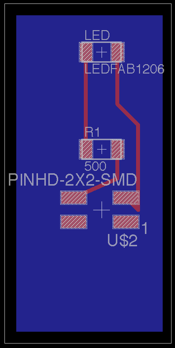
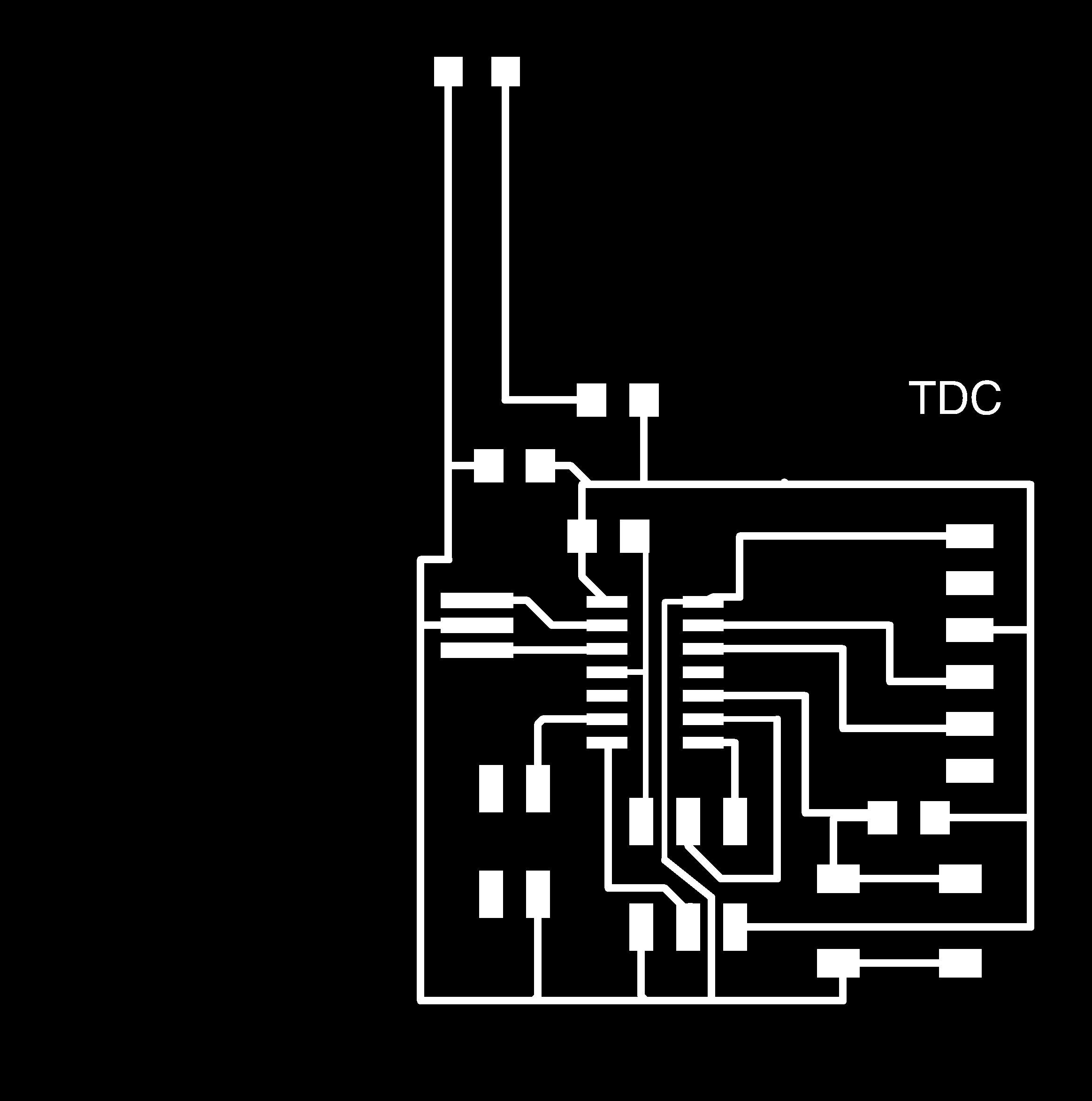
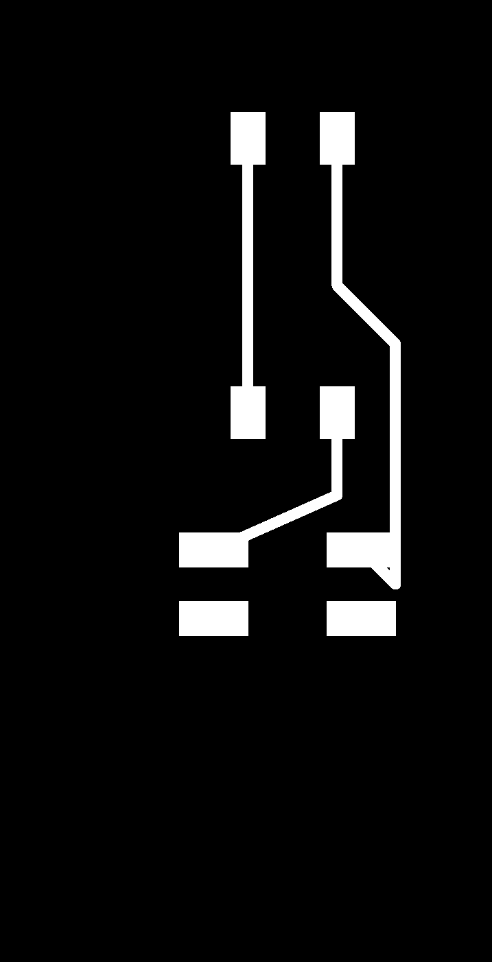
Exported the monochrome PNG's (all very similar to the Electronics Design week here. (note png's below are not to scale...on purpose)


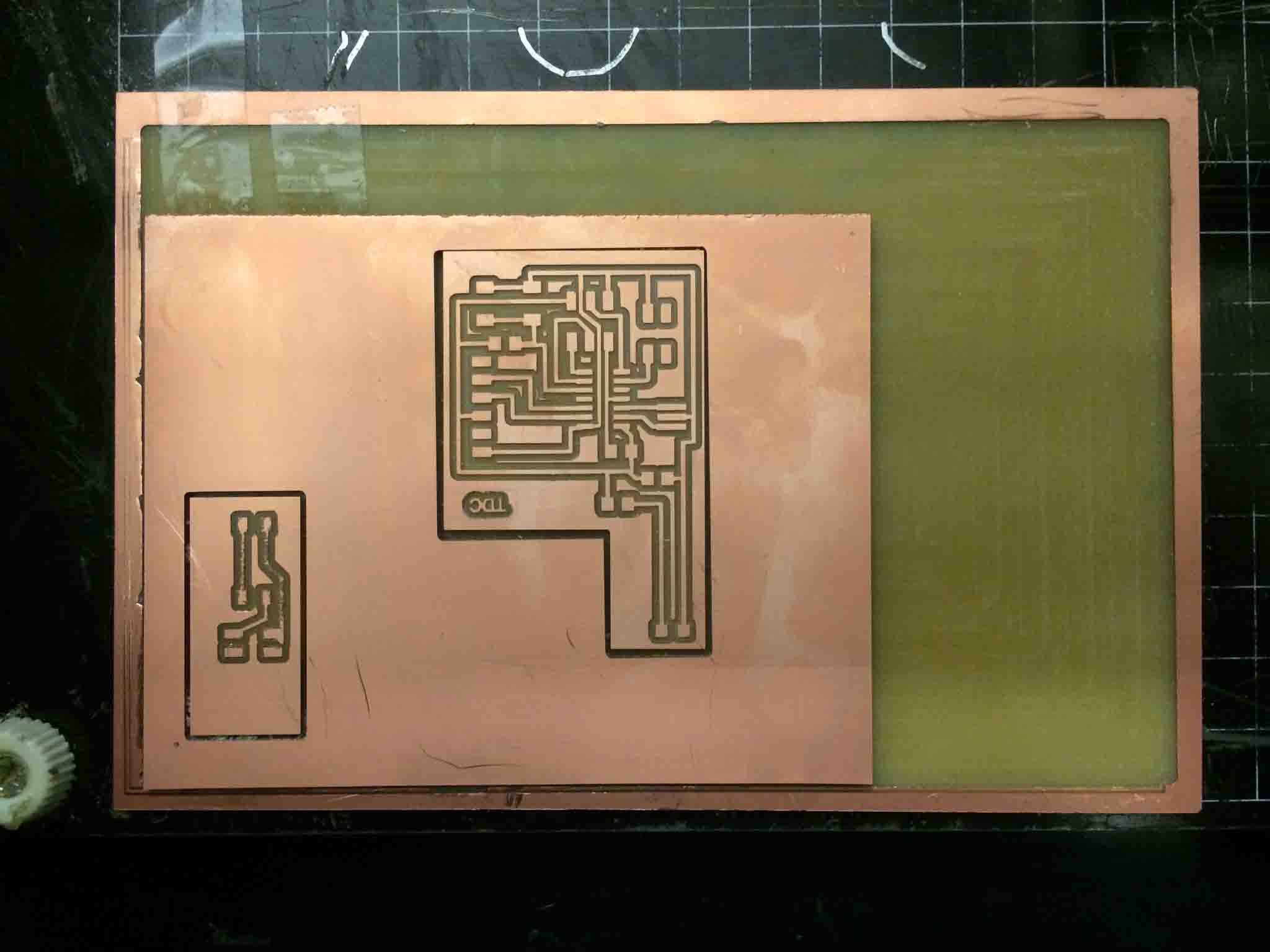
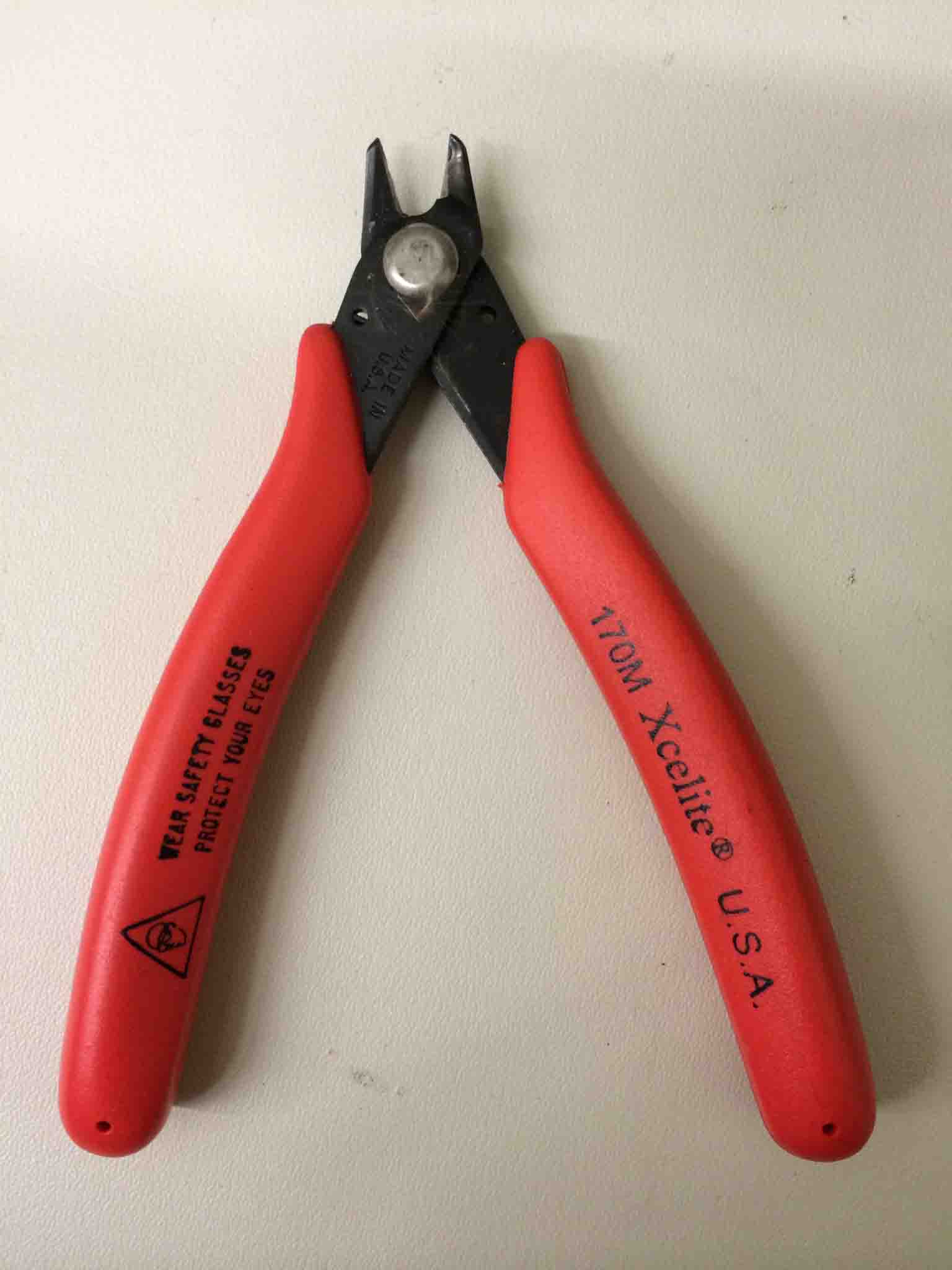
Set up the modela with to do two boards. Note that if the board you have is too big for your sacrificial plate, you can use the paper cutter behind the modela to slice through the PCB board. Also, when making FDTI headers or 2x2 headers, you can always take a larger set (a row of header pins or a 2x3 header) and use a wire cutter (like the red one below) to cut through it and make it to the number of pins you need.
Naturally, there were errors when first trying to program the board. Guru Diego and I tried but just weren't able to get it.
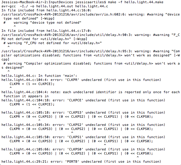
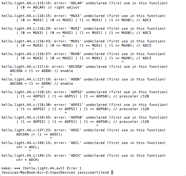
I finally found Charles Fraccia in his office and he worked with me all morning to get it done! There were some obvious, unavoidable errors, and some not so much. See tips above for a solid run down of these.
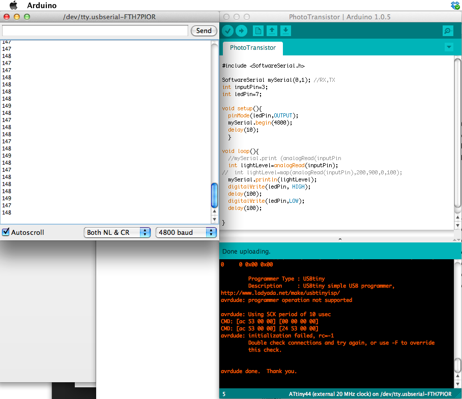
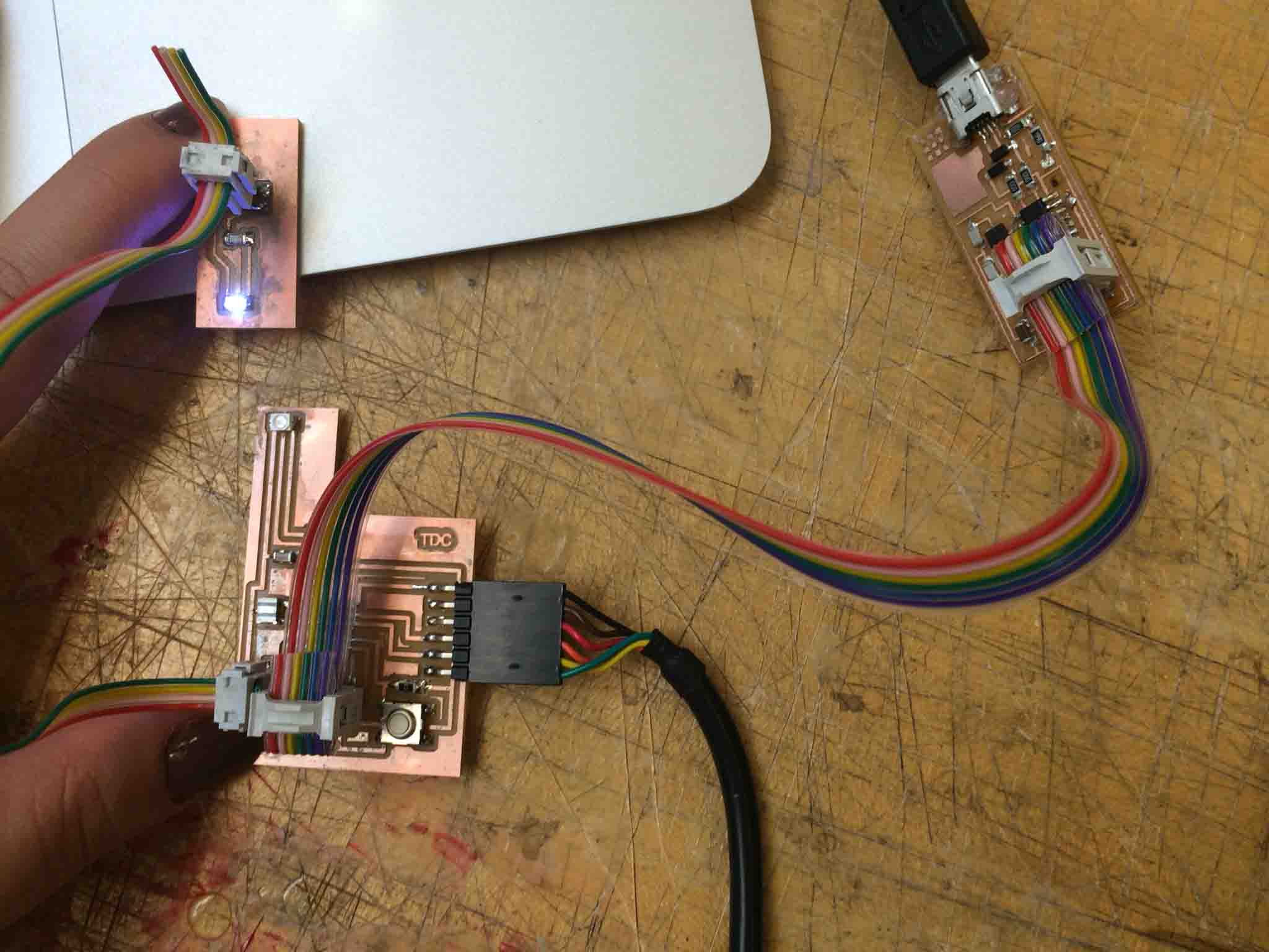
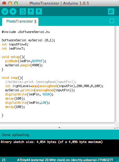
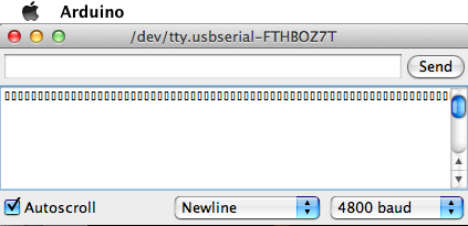
Finally! It works!
Here's a video of the final thing working!
Thank you so much to Prashant, Diego, and Charles for your kindness and patience!