Web Design, Version Control, and Final Project Brainstorm
Laser & Vinyl Cutting
3D Scanning and Printing
Make Something Big
Molding and Casting
Electronics Production
Electronics Design
Embedded Programming
Input Devices
Output Devices
Networking & Communications
Interface and Application Programming
Final Project
Final Project Idea from Week 0
The Follow Me Stroller
Are you a dad? Is your child young enough to be pushed around in a stroller? Are you tired of pushing your baby around? Then have your baby follow you around instead!I want to create a stroller, where my beautiful 2-year old daughter can sit, and have this stroller follow me around wherever I go. It should have 2 motors to drive the wheels, and a battery to juice the electronics. The dad should either have a receiving sensor for the stroller to track and follow, or maybe it can be connected to dad's phone through bluetooth. The stroller is then to maintain a specific distance away from dad, say 3-5 ft. If dad moves forward 1 step, it follows with the exact same distance. If dad turns right/left, it turns right/left. If an obstacle puts more distance between dad and baby that the constant distance, then receiver in dad's hand or his phone should ring loudly.
I still don't know what type of sensor is best for this application. I still don't know all the components I will need. I still don't know how to draw this. There is a lot I don't know, but I'll hopefully figure it out!
Here is the concept of what I envision this thing will look like (I know its missing wheels!):
There are a few things that need to be worked out:
1-I need to make the physical design in CAD in such a way that it can fit all the electronics. I also need to figure out how I will fabricate it.
2-I need to figure out the circuitry involved to drive the vehicle. I am currently thinking of using 2 motors on the front 2 wheels and using casters on the rear 2 wheels.
3-I need to figure how to track a single object, and calculate the distance to that object. The idea is to have the vehicle fitted with 3 IR photodetectors, and create a modulated light transmitter to be mounted on the person being followed.
4-I need to figure out the math involved in calculating the precise location a single point (transmitter) from 3 detectors. It is a non-trivial spatial geometry problem, but I feel that I can do it.
Actual Final Project
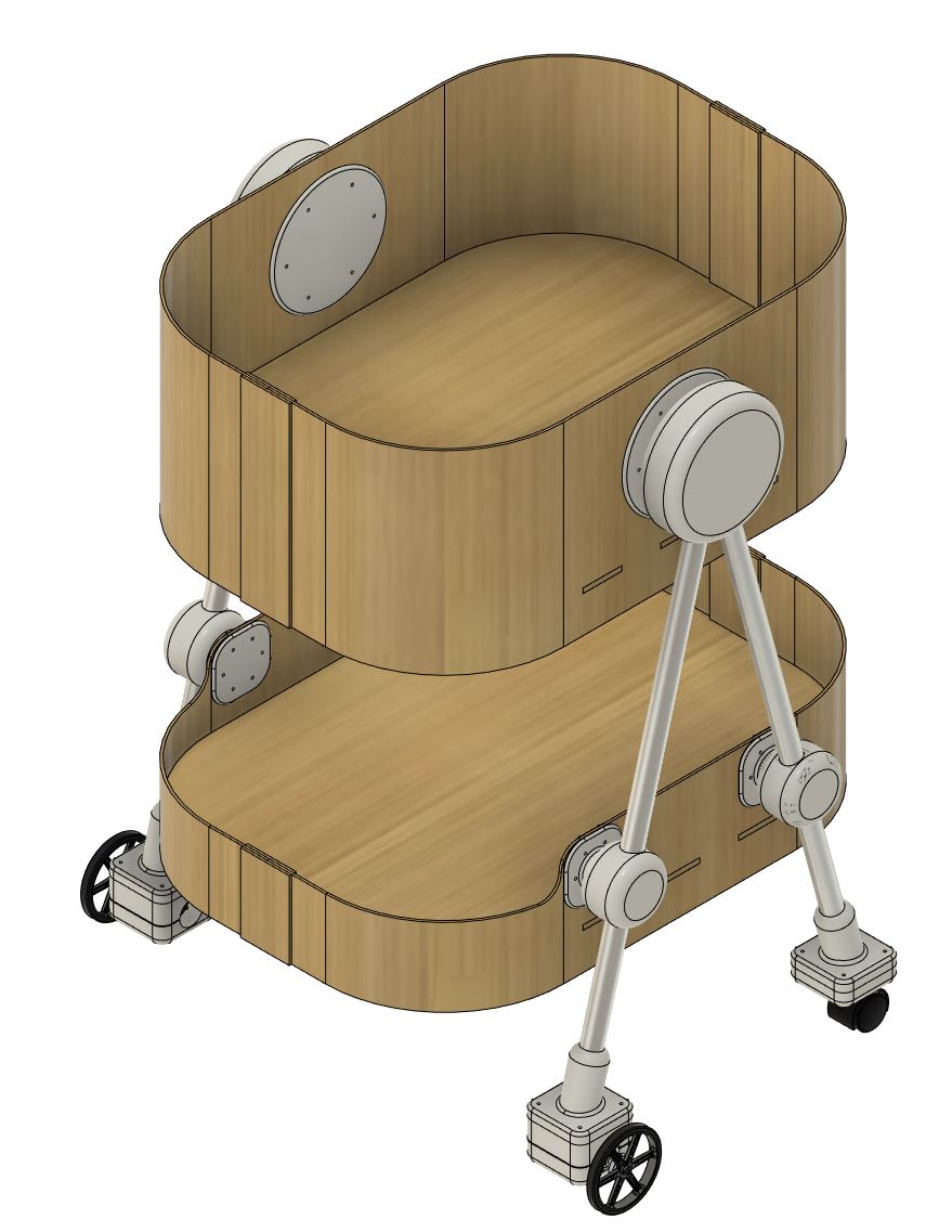
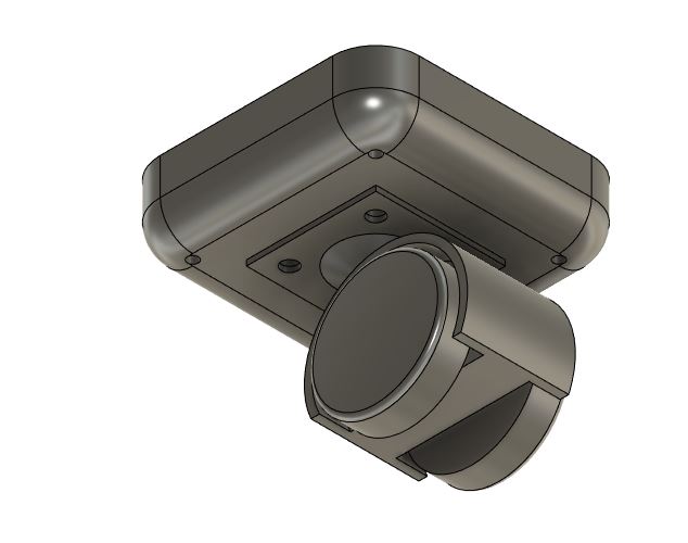
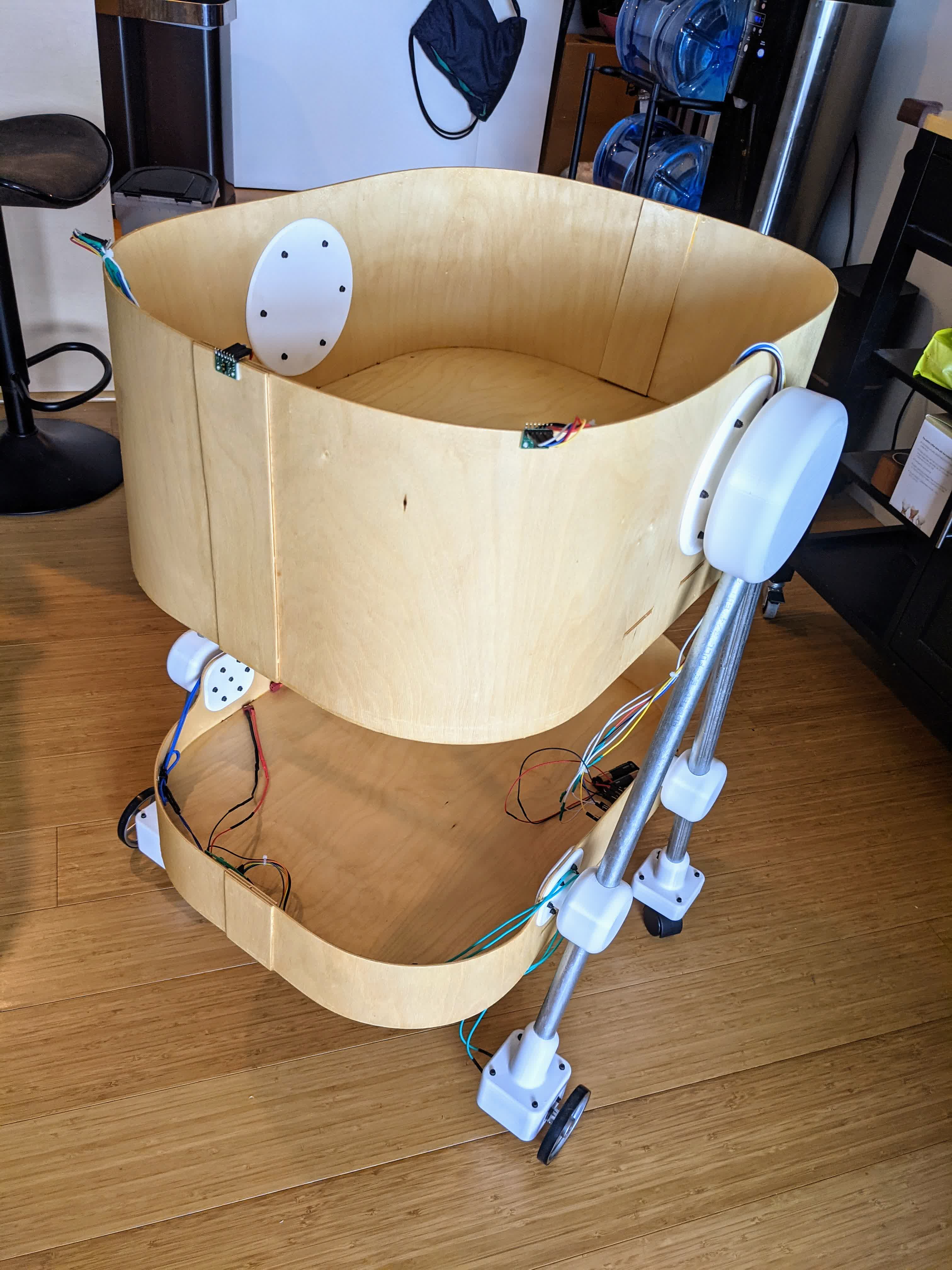
I managed to accomplish most of what I wanted to do. I made a stroller that can technically follow me, however, it is indiscriminate; it can follow anything. To work around this, I've changed the concept a bit. It is now a hands free stroller, ie no pushing involved. It requires the user to drive it just by standing a certain distance away from it. With this concept, I think its ok that it is indiscriminate, because now I, or my wife, or anyone I trust can drive the stroller. It gives a very weird feeling, like you're pushing without pushing.Below, I'll go through all that I went through to get there. Here's a sneak peak at the final design:
01 - Design
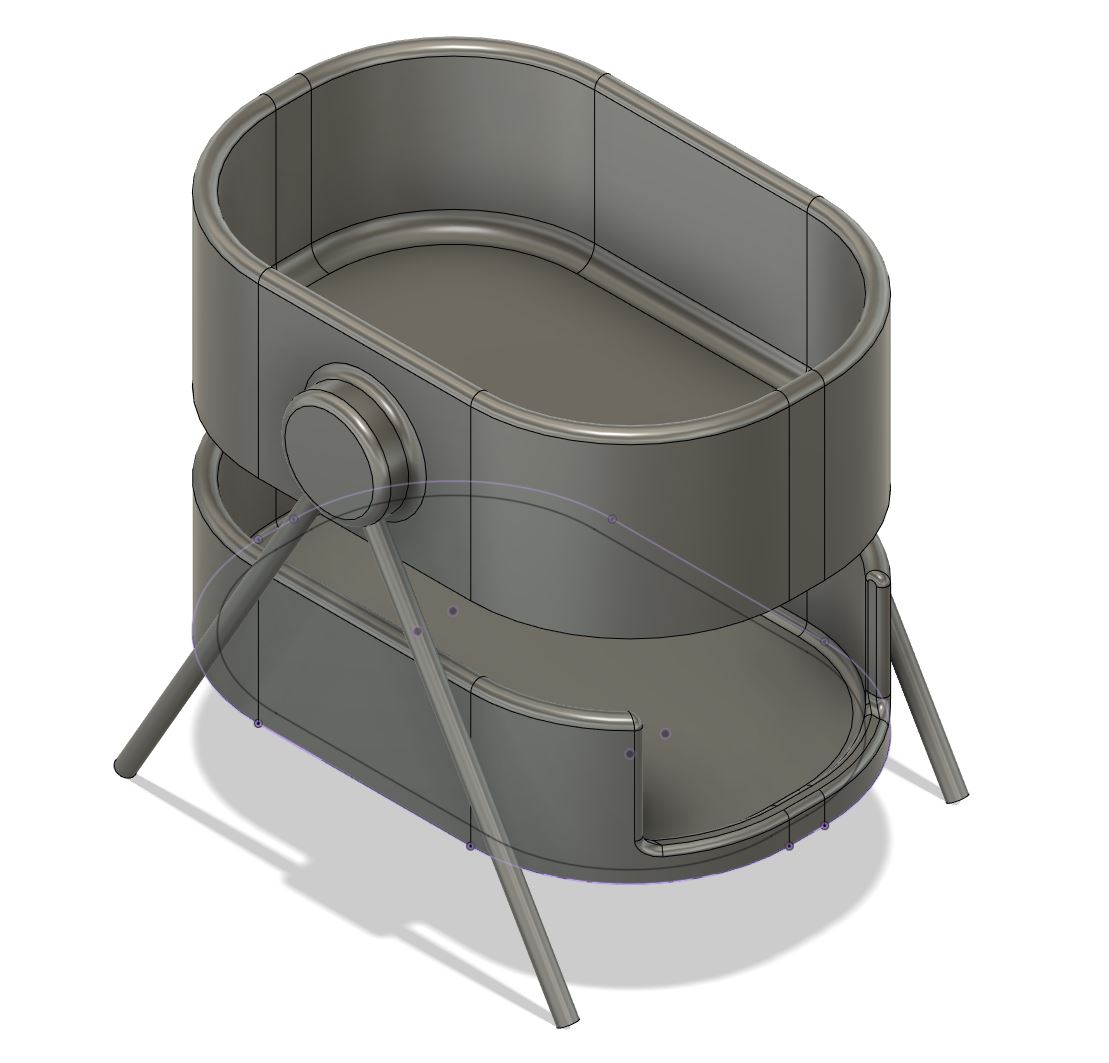
I am making a simple stroller design with a bassinet to hold a baby (or a toy baby since this may not be child safe), and the pouch on the bottom will house the main elctronics. The detectors will be designed to mount anywhere on the front of the stroller, maybe with double-sided tape.Physical fabrication
Before getting into the actual fabrication, it is important to discuss the design and all that goes into it. Unfortunatley, this is a multi-step process with lots of unknowns, such as not knowing the weight of the stroller which is a big factor in motor selection. Here is a CAD of everything besides the motors and wheels which will come in later.
This design is something that I feel I can fabricate, unlike my concept design due to all the curvy parts.
CAD
This design will have the following major components:-beds
-walls
-wall locks
-legs
-joints for legs
-Motor clamps
-Motor and wheels
-Casters
Beds
The bassinet and bottom pouch are identical and both have a base made of 1/4" baltic birch wood. I initially thought of making it 3/4" thick for some structural stability, but found that it would make the whole stroller too heavy for the motors to handle. The beds are designed with extruding slots that act as locators for the walls. They are 24" long and 18" wide. Here's the CAD of a single bed.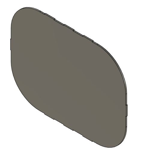
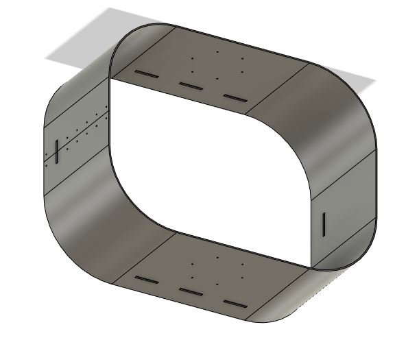
Walls
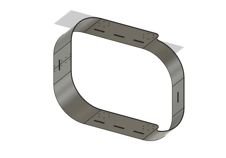
The walls of the bassinett and bottom pouch are made of the same material, 1/8" aircraft ply. This material was selected for its flexibility to wrap around the 6" radius of curvature of the beds. Both walls have slots for the locators from the beds to ensure symmetry and allignment for the wall locks. They also both have what I call skirts, 2 in below the middle of the bed, so the bed is not at the absolute bottom of the wall. They differ only in height, where the bassinett wall gives a 8" hight above the mid-thickness of the bed, while the bottom pouch gives a height of 4". The bottom pouch additionally has an accessibility cutout from the front until the next flat side begins, taking 2" off the height. They also have different hole placement for the hubs and wall locksHere is the top wall:
Here is the bottom wall:
Wall Locks
The wall locks are basically plates made of the of the 1/8" aircraft ply with holes drilled into them. They act essentially as washers on both sides of the walls to be fastened with M3 screws and nuts. Here they are on the top and bottom walls ensuring they remain secure: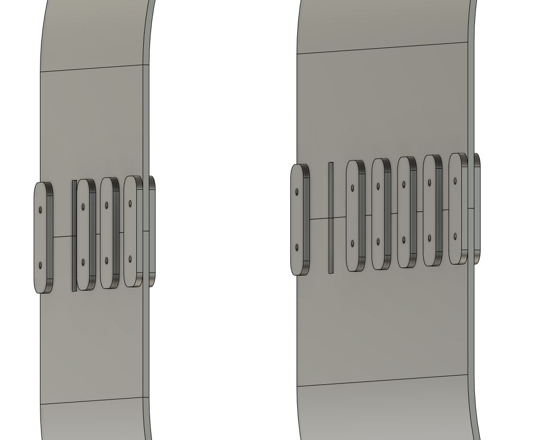
Update: I eventually had to abandon the fastener style wall locks after I discovered the physical fabrication of bending wood left a larger than designed gap. I instead used panels on both sides of the walls and glue to ensure the walls hold. The panels are depicted in the second image on this page.
Legs
The 4 legs are made of aluminum tubes with an outer diameter of 0.923" and an inner diameter of 0.813". This stock was available in the shop and is what I used. They are designed to be 2' long each.Joints
There a few types of joints in this design. All joints are to be 3d printed.Big Hub
A pair of big hubs mount on the bassinet long walls and are each paired with a plate which acts as a washer on the other side of the wall. It has 2 main cylinrdical cutouts that are a tight fit over the leg rods. In addition, the hub and its pairing plate have 6 M3 screw holes (I know 6 may be redundant and overdesigned, but better safe than sorry!) which line up with the holes on the wall. The hub and its plate will mount with the wall with screws while the legs simply slide in and will stay in due to gravity. Here is an image of the hub and plate: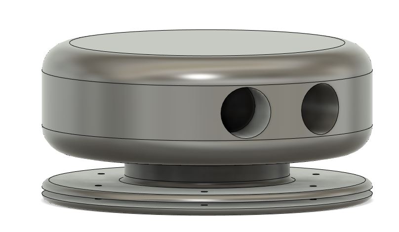
Small Hub
There are 4 small hubs that mount on the bottom pouch and are each paired with a small plate also acting as a washer on the other side of the wall. These hubs have a through hole for the rods to go through, and will provide stability to the system. The angle of the through hole matches that of the big hub (75 deg from vertical), so when the rod slides through both, with both hubs fixed on the walls of the bassinett and bottom pouch, gravity will do its work while the hubs keep the legs pinned in 2 places. Here is an image of the small hub and its plate: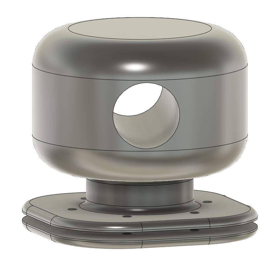
Leg Sleeve
Each of the rods ends at a sleeve which ends in a plate that is normal to the ground. The plate has M3 sized screw holes to mount the motor and wheels. motor and caster mounts could have been designed on the same piece, but I opted for this more modular design for some flexibility with what I want to mount since I am prototyping. The sleeve overlaps 2" of the rod and has an outer diameter of 1.5". The plate is 3"x3" to accomadate most motors and wheels. Here is an image of the leg sleeve: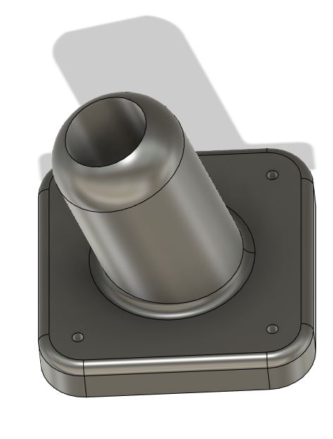
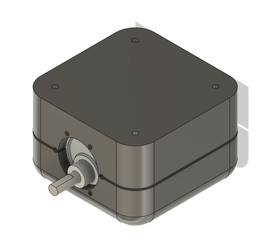
Motor Mount
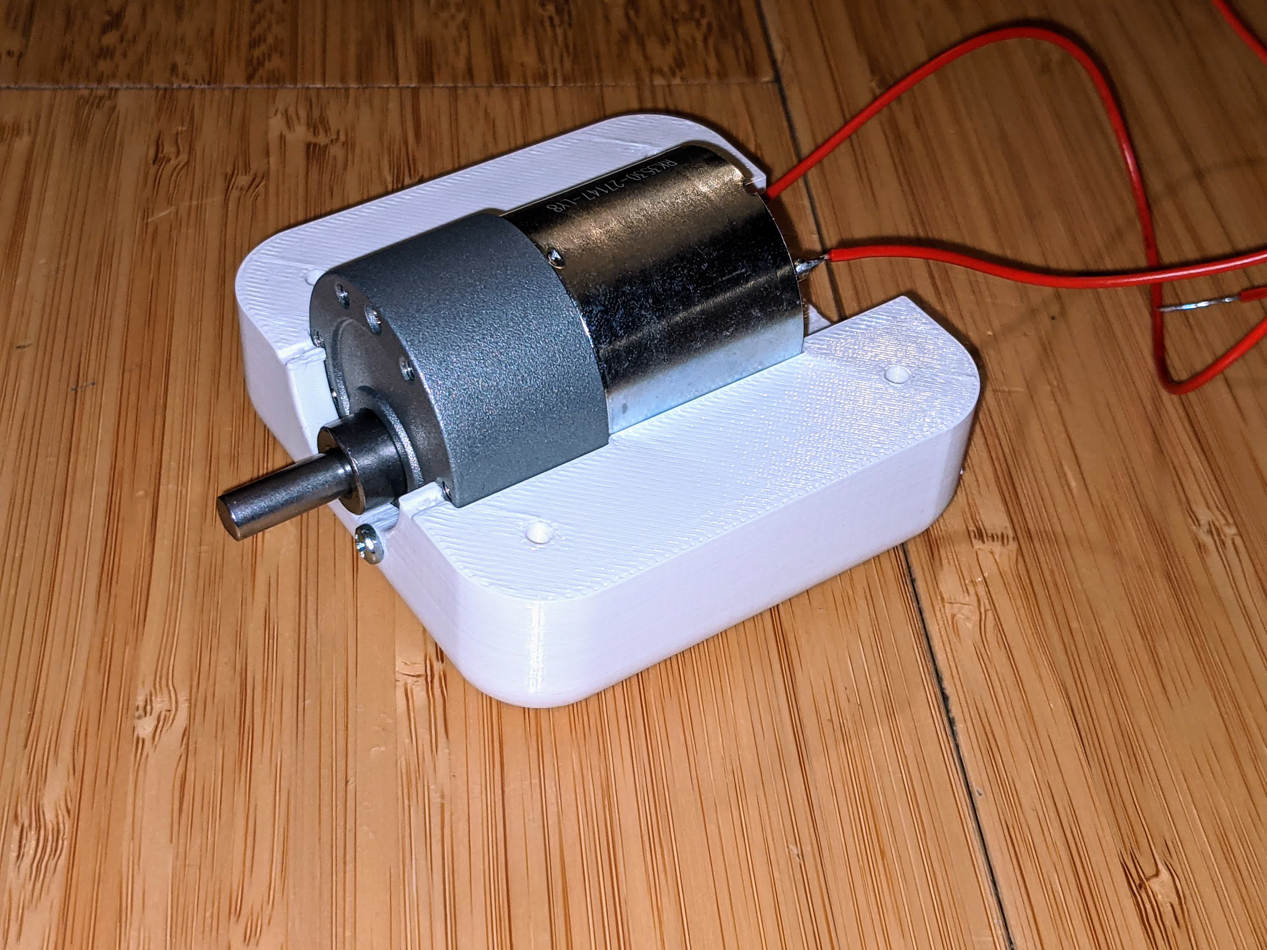
Designing the motor mount depended heavility on selecting a motor. I knew that most motors are in the range of ~1" diameter and 2" of length, which is why I made the base of the leg sleeve 3"x3". I eventually settled on a motor, described below, and designed this motor clamp. It is designed to completely house the motor within 0.005". I imported the motor I selected from Pololu's website. I then designed around it a top and bottom clamp with an enclosure that perfectly fits the motor, but oversized by 0.005". I also created a 1mm gap between the top and bottom clamp to give it a flexural clamping force. Here is an image of the top clamp showing how the motor fits inside: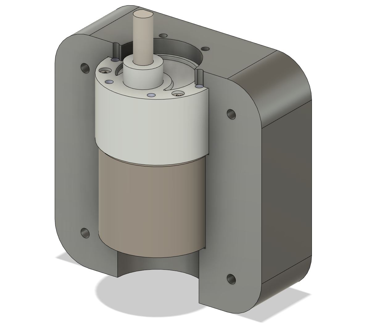
Here are both clamps showing the flexural gap:
You can see here that there are a few holed on the face of the clamps. These are designed to pin the orientation of the motor and fix it. It may be unnecessary to have 6, in theory, I only need 1 hold to fix the top clamp to the motor, but better be safe than sorry. These holes' diameters match those of the motor, and after 3d printing the clamp, I expect the screw to tap threads into the clamp. Update: I learned that this is not a good idea. The plastic that the screw will cut has no where else to go but inside the motor, which is probably not good for the gears. In the future, definitely make these holes larger. The only point of this hole is to prevent motor rotation, so it can be slightly larger than the screw.
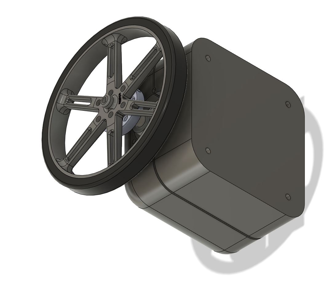
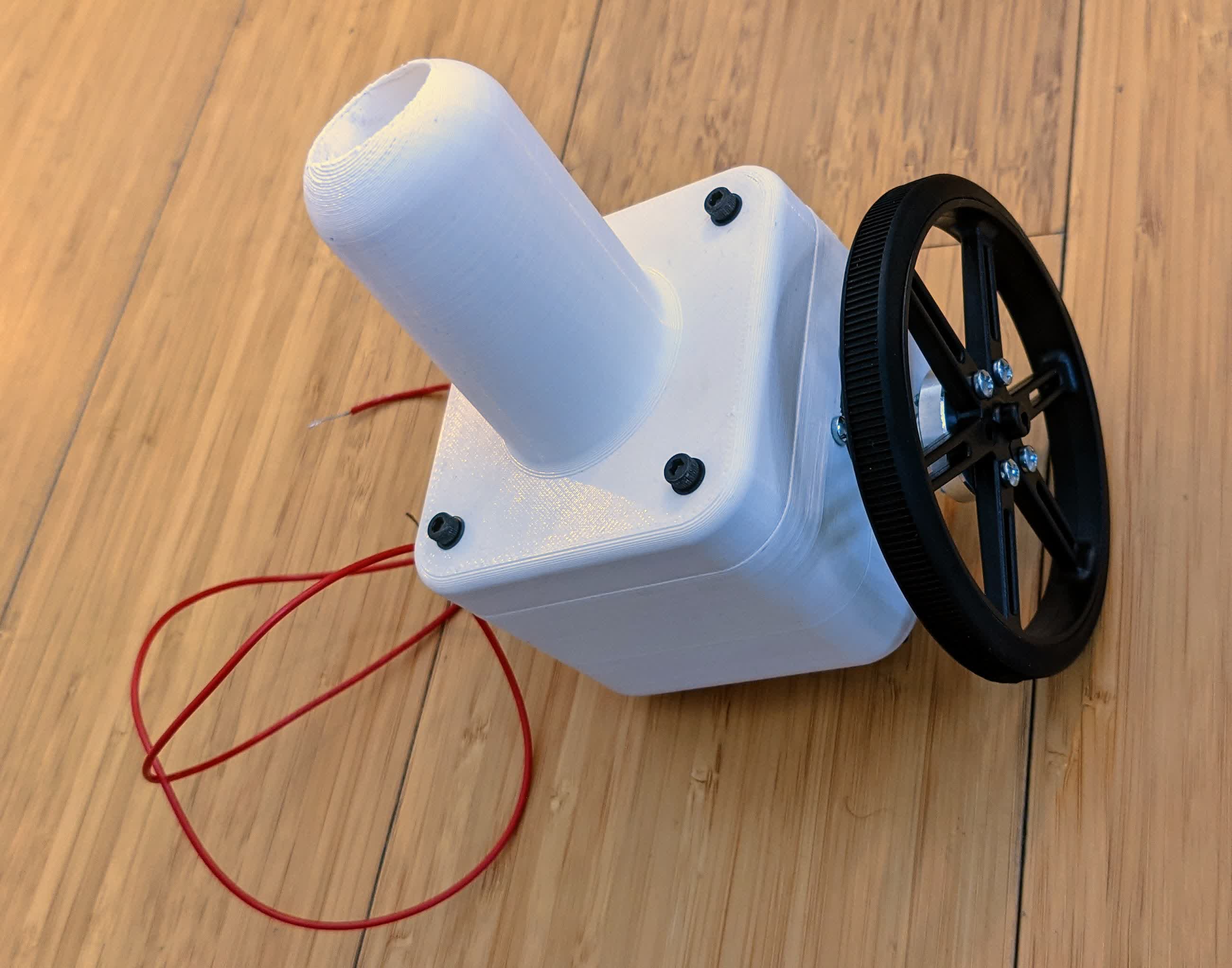
Here is the motor and wheel assembly from the front showing the wheel and hub in place:
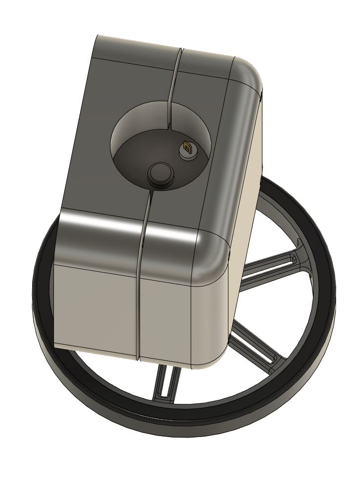
Finally, here it is from the back showing a big slot for the motor wires to come out of:
Caster Mount
The major design consideration for the caster mount assembly is the height. After designing the motor assembly, I can see the exact height from the bottom of the wheel to the bottom of the leg sleeve. So after picking a caster, I just needed to make a caster mount to fill in that gap for the stroller to stand perfectly level.picking a caster was not too tough, I just needed something that was smaller in height than the bottom of the wheel to the bottom of the leg sleeve. I went with this.
I designed the mount with embedded screw holes to mount the casters to, so that they stay hidden and I can still mount this adapter to the bottom of the leg sleeve.
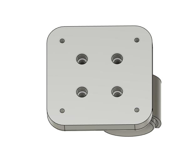
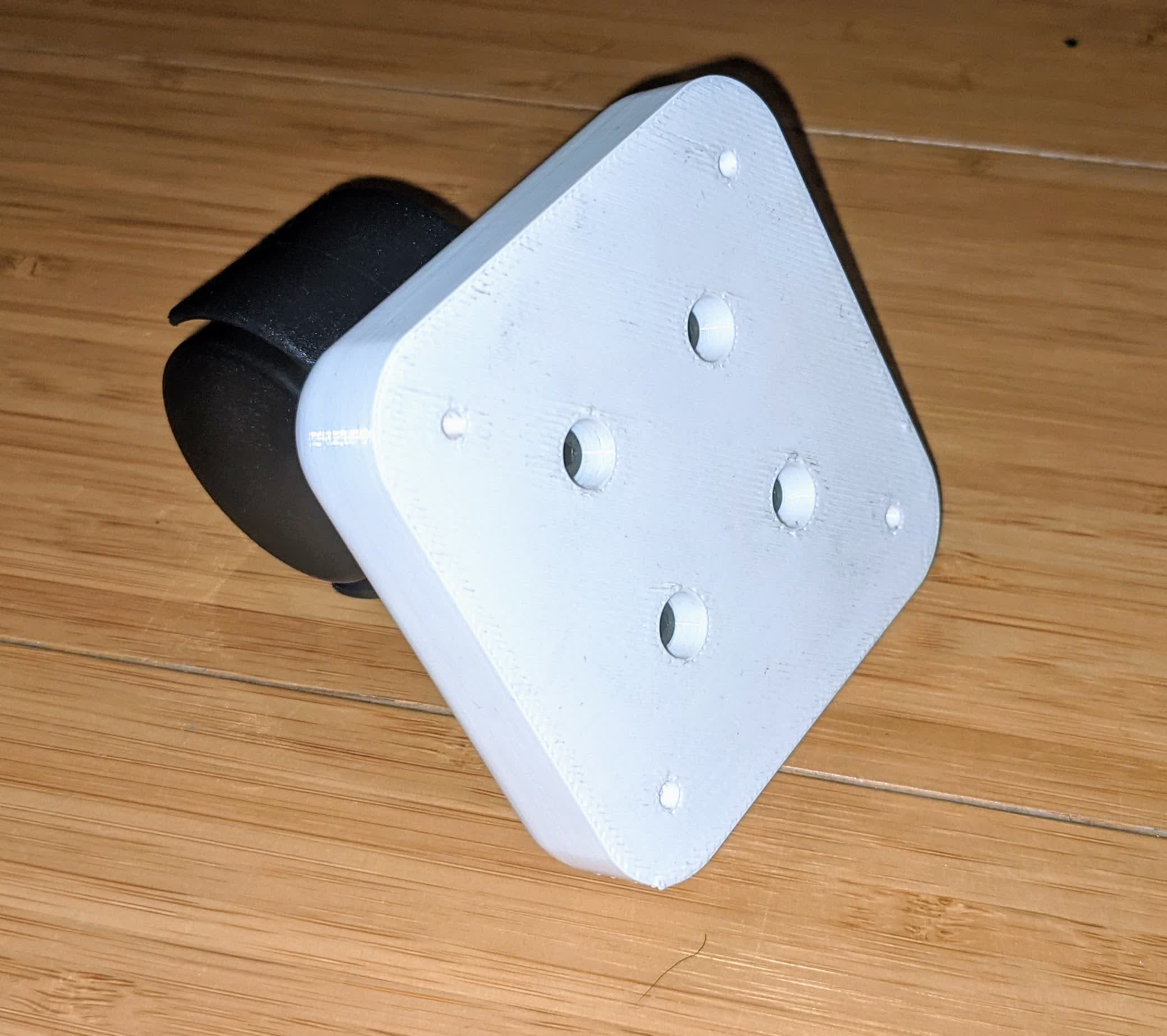
Here is the top view of the adapter showing the embedded screw holes:
Here is what the caster assembly looks like:
Motor and Wheels
The motor selection process really depends on the weight of the all the above components and the desired speed I'd like this stroller to go. I decided not to fabricate wheels as they are cheap to buy and readily available with adapters to fit directly on the motor shaft.I went to Pololu to buy 2 motors for my stroller. Here is a list of the gear motors they offer. I am going to stick to 12V motors because I'd like to power this with batteries eventually. The goal is to select motors that can provide enough torque to drive the stroller (given its weight) and provide enough speed to allow the stroller to achieve average human walking speed - 1.3 m/s.
I could have 3d printed wheels to fit on the shaft, but opted to buy them given their low prices. Here is a link to the wheels provided by Pololu. I am going for the 90mm wheels. I will also have to buy the universal mounting hub for 6mm shafts (the shaft diameter of the motors) since the wheels were designed to fit a 3mm D-shaft, and the 37D gear motors I am looking at all have a 6mm diamter shaft. The wheel dimensions are a bit unclear on how thick the part with the hub mounting screws are, so I am assuming the worst case of 10mm thick. The #4-40 hex nuts are not provided, but a quick Google search shows they are about 3/32" (2.38mm). The universal mounting hub has a thickness of 5mm. So I will need #4-40 screws that are approximately 10+5+2.38 = 17.38 mm (0.68") long to mount the wheel to the universal hub. Obviously, they don't sell or make such a specific dimension, but they do sell 3/4" long screws, so I'll make due with that.
Motor Selection
To calculate the motor requirements, ideally, I need to measure the weight of the entire stroller. However, since it is not fully fabricated, I am estimating the weight. From the CAD, I pulled the volumes of all components. I then tabulated the material each component is being fabricated from, thier respective densities, and then calculated weight. Here is a table showing these estimates: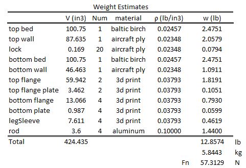
The From here, we see that the total normal force of the stroller is 57.3 N. Here are some assumptions:
-D=90mm wheel diameter
-mu=Coefficient of friction between wheel treads and ground is 0.9
-mu_r=frictional rolling resistance is 0.05 (a bit conservative)
From these assumptions we can calculate the frictional force we need to overcome to slide the stroller: F_f = mu * F_n = 0.9 * 57.3 = 51.6 N. We can then calculate the torque required per motor: T = F_f * (D/2) / 2 = 51.6 * 0.045 = 1.16 N-m which is equivalent to 11.83 kg-cm. I divide by 2 because there are 2 motors driving the stroller. This is considered a worst case scenario because we are not actually sliding the stroller.
Another more realistic calculation is to calculate rolling force since the stroller is on wheels. It is difficult to estimate the rolling force required because I really don't know the rolling resistance of the motor shaft, but this is a ballpark calculation:
The weight on each wheel is F_n / 4 = 57.3 / 4 = 14.33 N
The rolling force resistance per wheel is F_r = mu_r * F_n/4 = 0.05 * 14.33 = 0.716 N
The torque is then calculated as F_r * D/2 = 0.716 * 0.045 = 0.032 N-m which is equivalent to 0.329 kg-cm.
This is considered the torque I need for continuous rolling, but the torque required for initial rolling from stop is higher (similar to the difference between static and dynamic friction). I could not find a reliable way to calculate this, but I found some sources online that claimed it is 2-3 times higher than the continuous rolling resistance. So assuming worst case scenario, the torque I need to start rolling from a dead stop is 3*0.329 = 0.986 kg-cm.
One final note is that all the 37D gear motors provided by Pololu have torque ratings, but they all have a cap of 10 kg-cm of continous torque output. The reported values are actually extrapolated values of stall torque, meaning this is how high they can go before stalling, but they cannot sustain this. I was really worried that the tiny 12V DC motors might not be able to provide enough torque, but it seems like I am safe. Given my worst case estimate of 11.83 kg-cm, I have to pick the 30:1 gear ratio motor (stall torque of 14 kg-cm) or higher. I think this works out just great, because for this particular motor, it has a no load speed rating of 330 rpm. Translating this into stroller speed, we get: pi*D*RPM = 3.14 * 0.09 * 330 / 60 = 1.55 m/s. We can also estimate the load speed from the datasheet. They provide a relation between speed and torque: RPM(T)=320-2.2*T; assuming our worst case torque, we get at a load of 11.83 kg-cm an RPM of 320-2.2*11.83= 293.96 RPM, which is equivalent to 1.38 m/s. So the 30:1 gear ratio motor theoretically meets both torque and speed requirements.
Casters
The back wheels are simply standard casters. The motor and caster mount is deisgned to ensure they all keep the stroller level.Fabricating
As stated above, the bassinett and bottom pouch are to be CNC'd and the joints are to be 3d printed.CNC
The top priority went to making the bassinett and the bottom pouch. I was limited on time due to campus shutting down early.beds
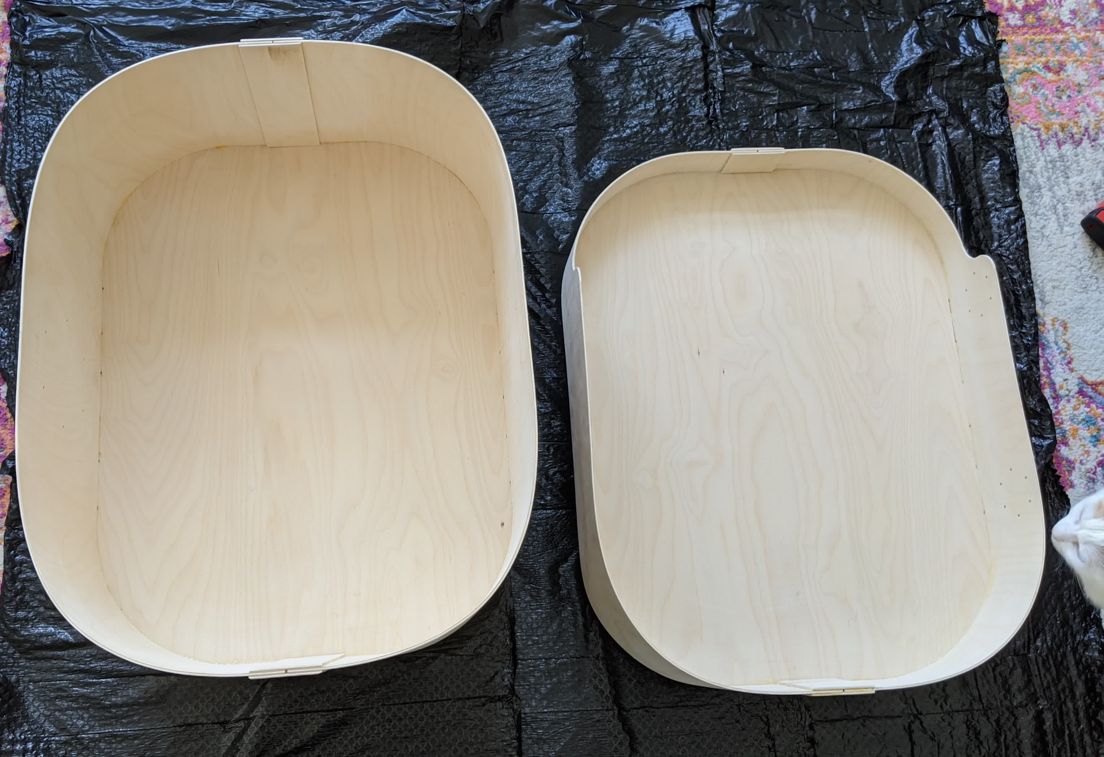
The base of the bassinet and bottom pouch are identical and were made of 1/4" baltic birch. It was standard 2D CNC procedure (like the make something big assignment) and here are the results: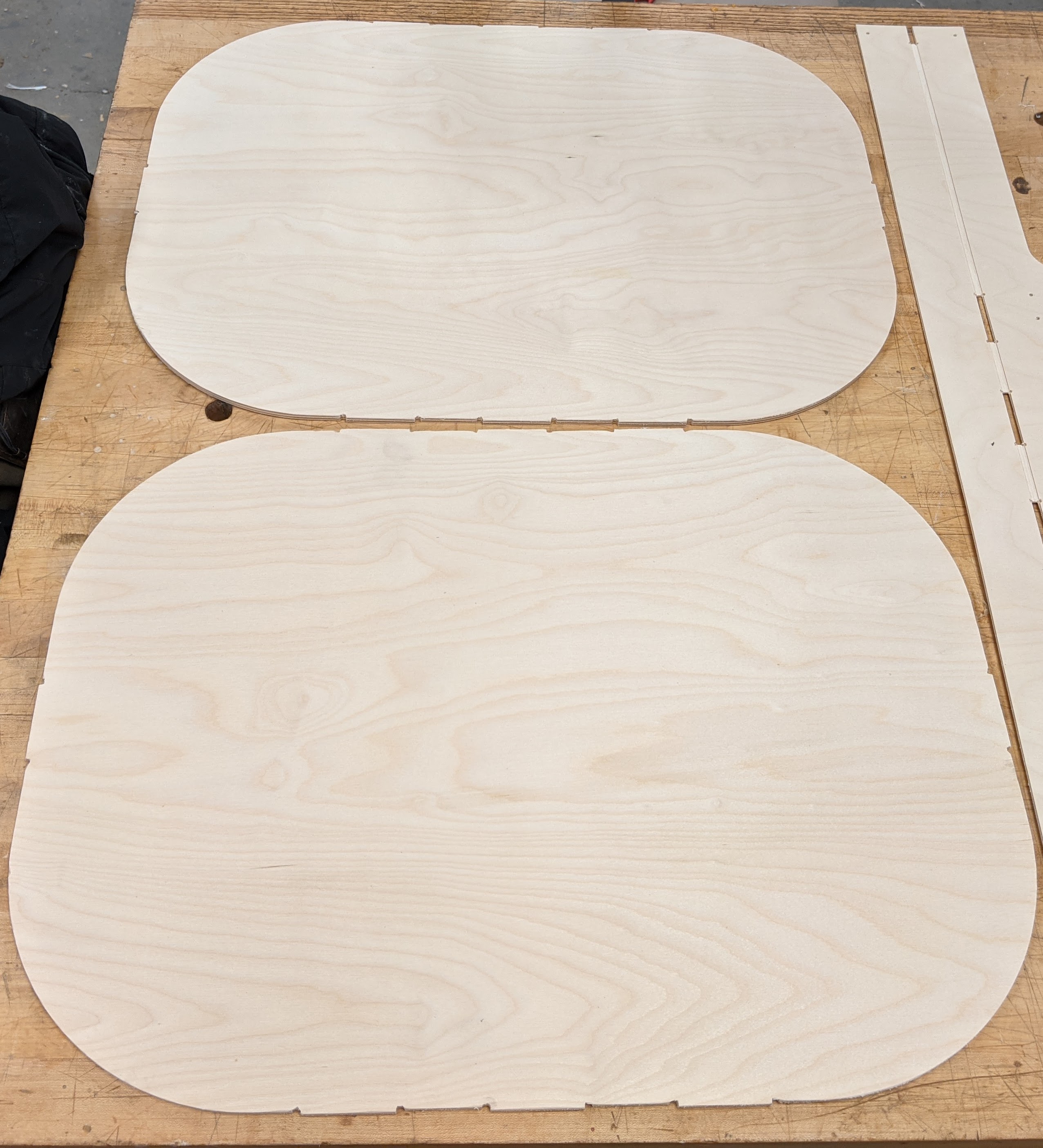
Walls
The walls are designed to be made of 1/8" aircraft ply. They were tricky for a few reasons. First, I didn't know that it would actually be able to bend as much as I designed it to. So I cut a 12" wide strip and did a quick test: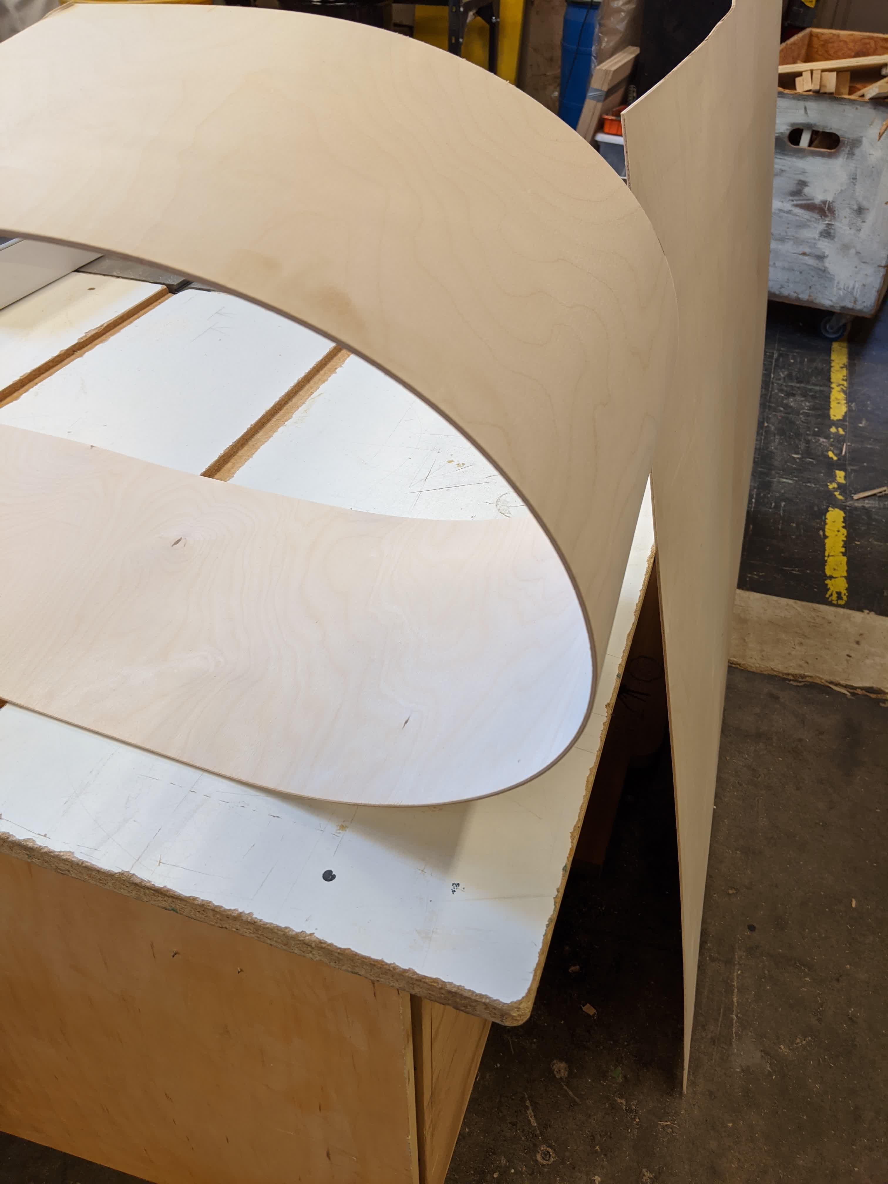
It looked promising. It is worth noting that this wood only bends along the axis of the wood grain. The other issue was that given the base dimensions of 24"x18", I needed to wrap around 7' to cover the perimeter, but the only thing in stock was 5'x5' sheets of aircract ply. So I had to do some last minute adjustments to the design and make the wall into 2 pieces rather than the single piece wrapping around. I simply cut the original deisgn down the middle and copied the lock ends onto the cut side to make it symmetrical. In addition, I added a 1/16" deep groove connecting all the slots as an extra safegaurd to ensure proper placement during assembly. Finally, I decided to cut the wall locks out of the same material, but oriented them perpendicular to the walls so they are more rigid along their long axis. Here is the redesigned CAD where the wood grain would be horizontal:
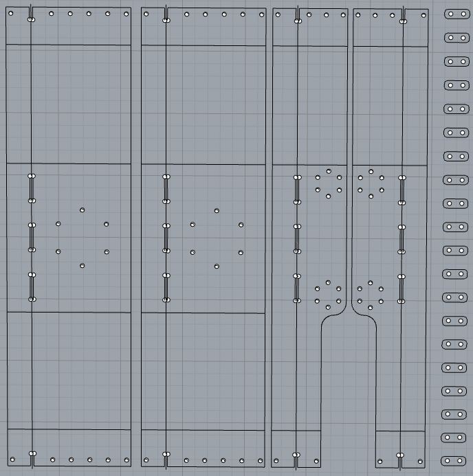
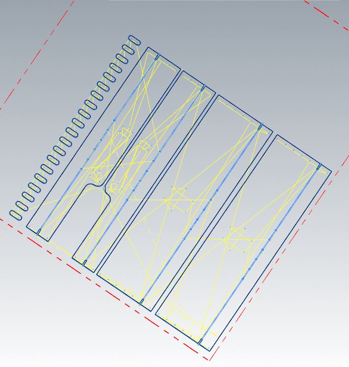
Once that was done, it was back to the Onsurd to do the cutting. Here is the tool path where holes are drilled first, then slots cut out, then borders cut out:
We always start with air cutting:
Here we are drilling holes:
Here we are cutting out the slots:
Here we are carving out the groove between slots:
Here we are cutting out the borders:
Here are the locks:
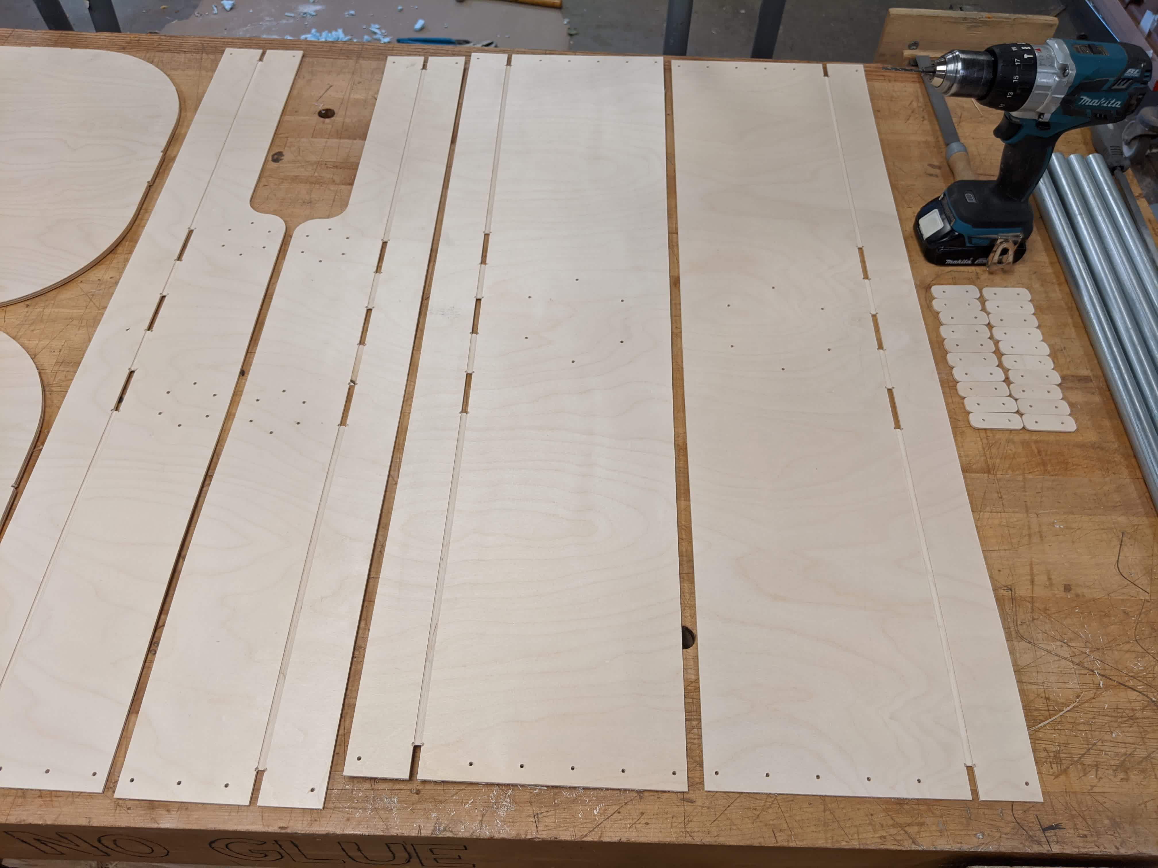
Here are the walls and locks after cleaning up the onion skin with a file and hand drill on the holes:
Legs
I took the aluminum pipe that was in stock and cut 4 pieces that are 2' long each using a saw. I then used a file to clean up the edges.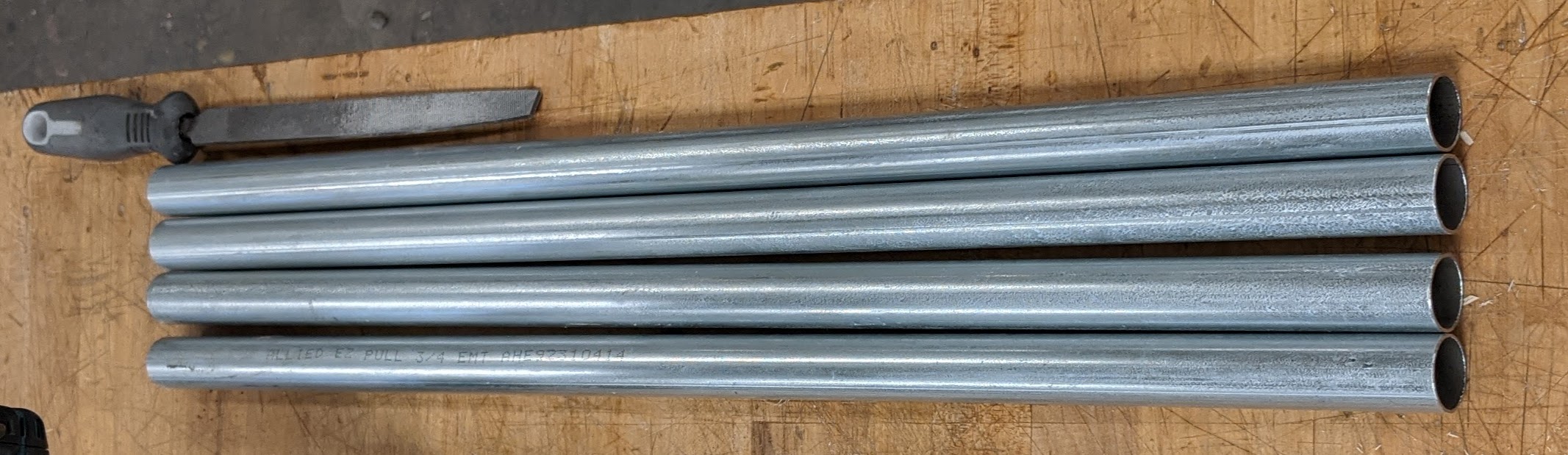
3D Printing
The following items were 3d printed:-2x big hub and big plate
-4x small hub and small plates
-4x leg sleeves
-2x top motor clamp
-2x bottom motor clamp
-2x caster adapter
The prints were done with a 1mm thick wall, and 15% infill to keep everything as light as possible. These don't need to sustain heavy loads, so I thought it was fine. Here are all the 3D printed parts:
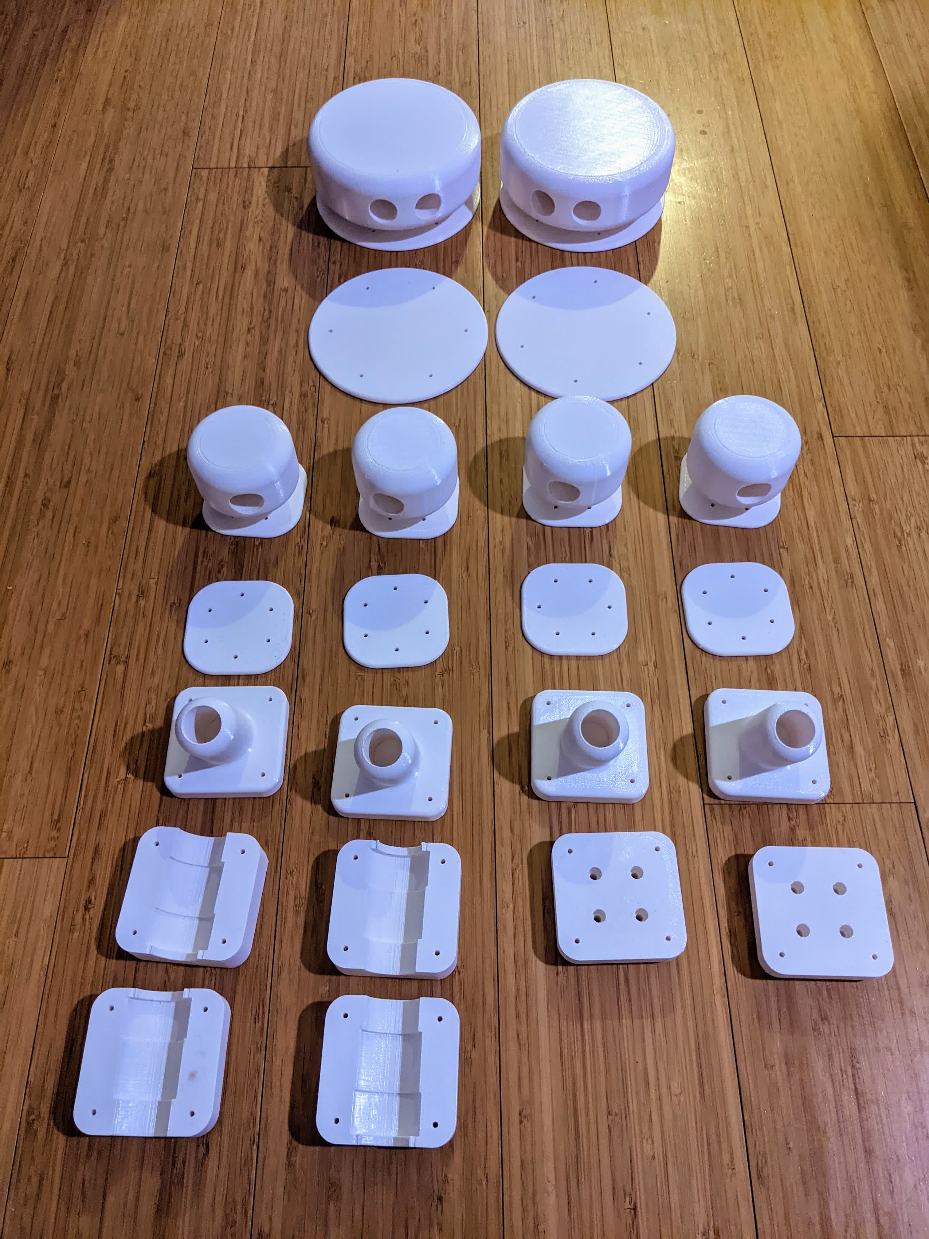
This took about 4 days of printing. The printing was segmented based on the 10"x10" bed dimensions, basically fitting whatever I can for any print job. Each job took ~10-16 hrs, and I did this over 4 iterations, hence my 4 day estimate.
With this done, I am ready to start assembly.
The final CAD design can be viewed here
Assembly
I began by assembling the CNC's parts, and then the 3D printed parts. The legs are ready to go as all they need to do is slide in.CNC'd Parts - Bassinet and Bottom Pouch
Here is an image with all the cut pieces: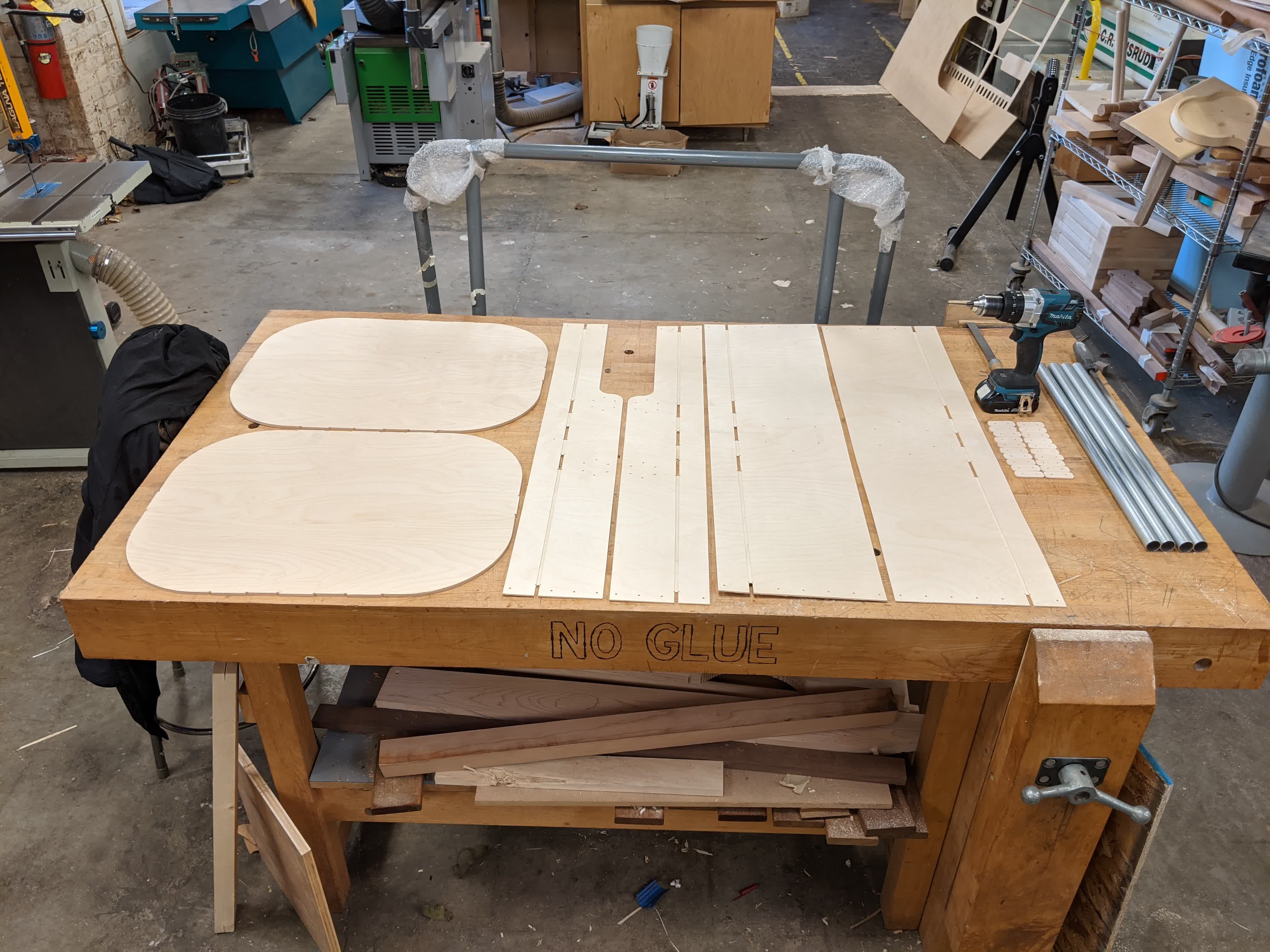
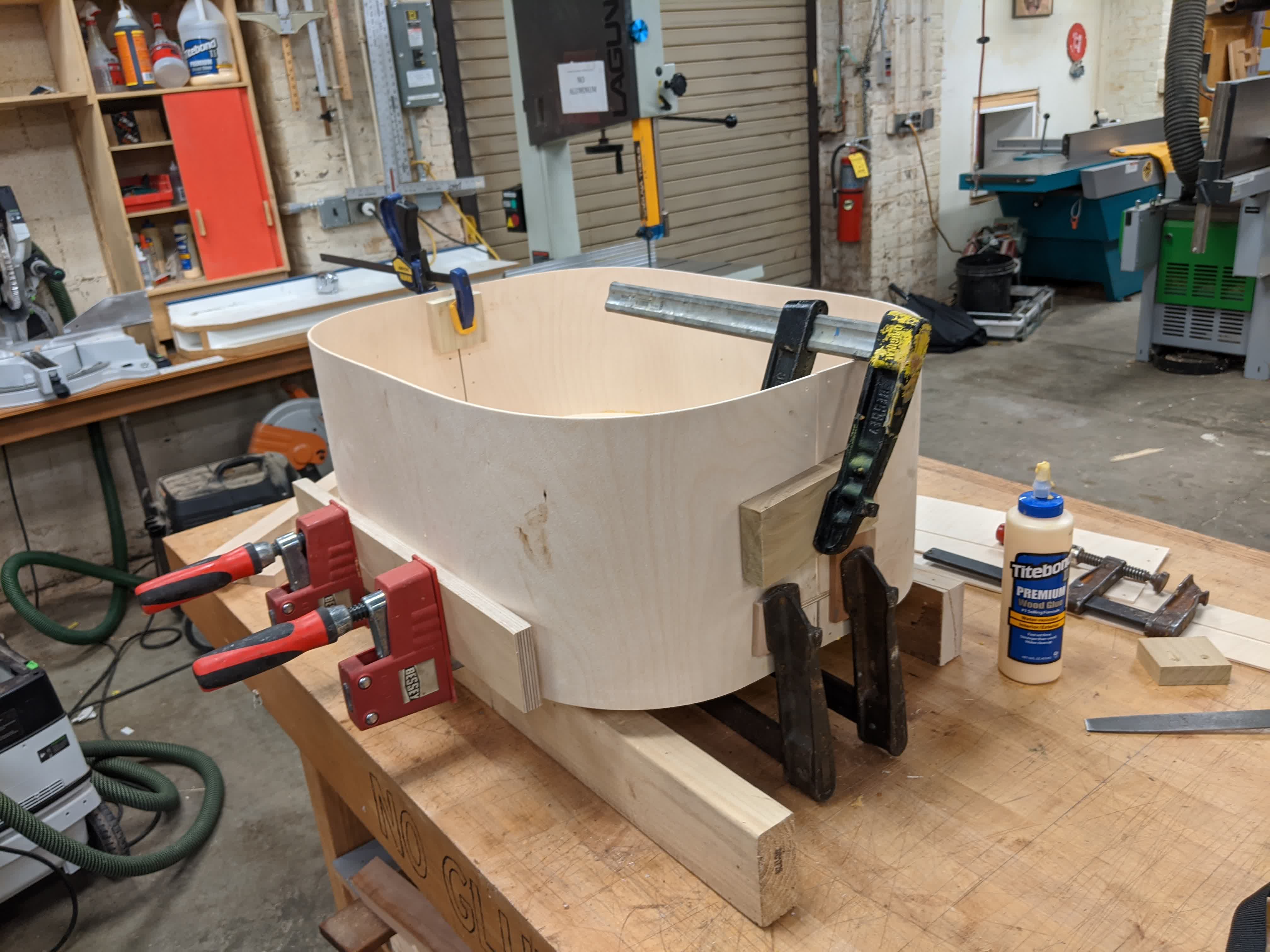
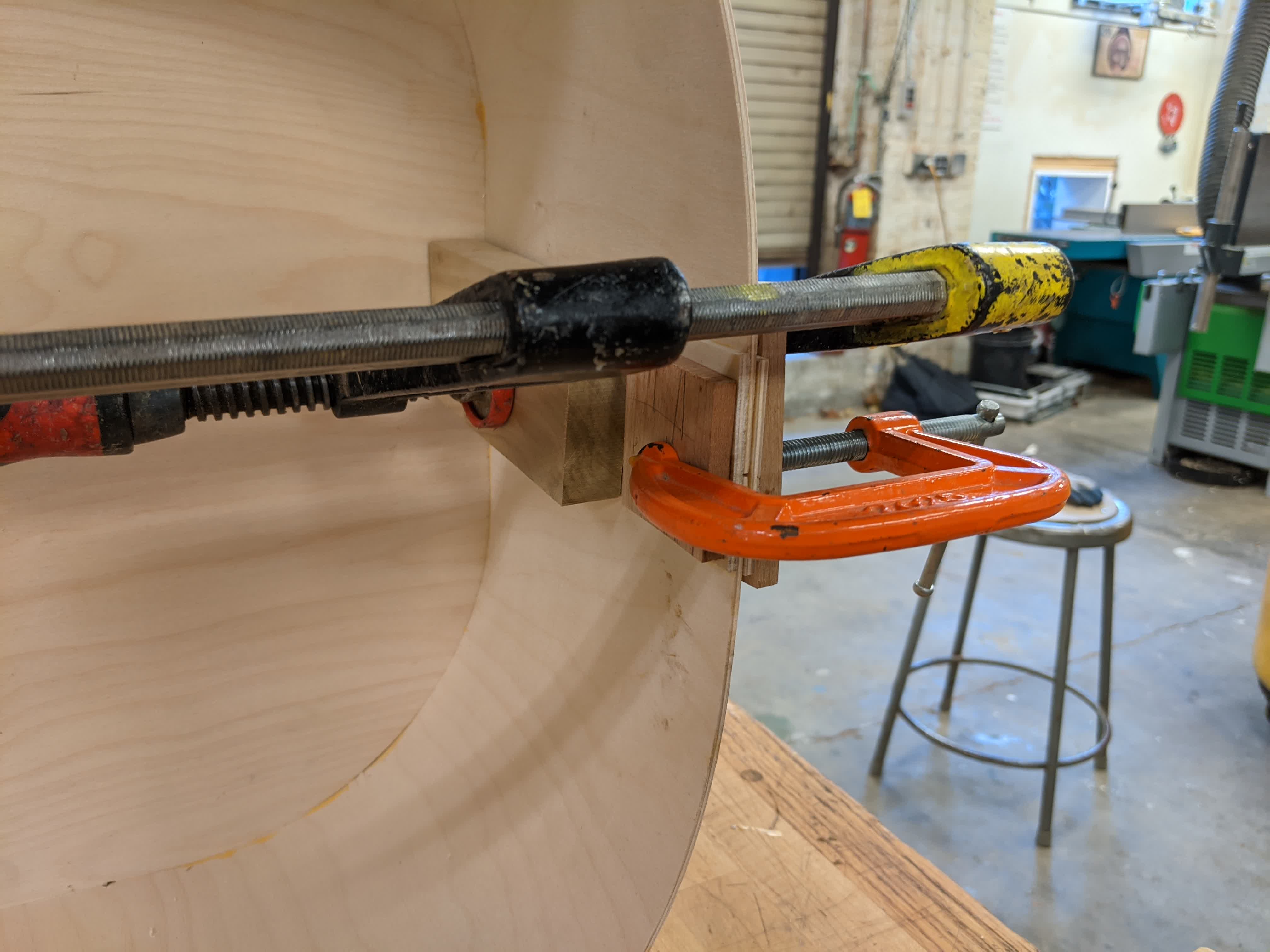
I started with the bassinet. It was quick game of applying wood glue along the groove of the wall pieces, then wrapping around the bed, and applying a bunch of clamps. It took 2 people to do this in a timely manner. Overall, it was a pretty smooth and straight forward process. The groove covered the bed, and the slots when into their spots. Here's the bassinet coming togther.
I did this for bothe the bassinet and bottom pouch. I left them overnight to cure, then removed all the clamps. I then started putting on the locks with M3 screws and nuts and faced a problem. The gap between the two pieces was too big! I guess this is where design and practice differ.
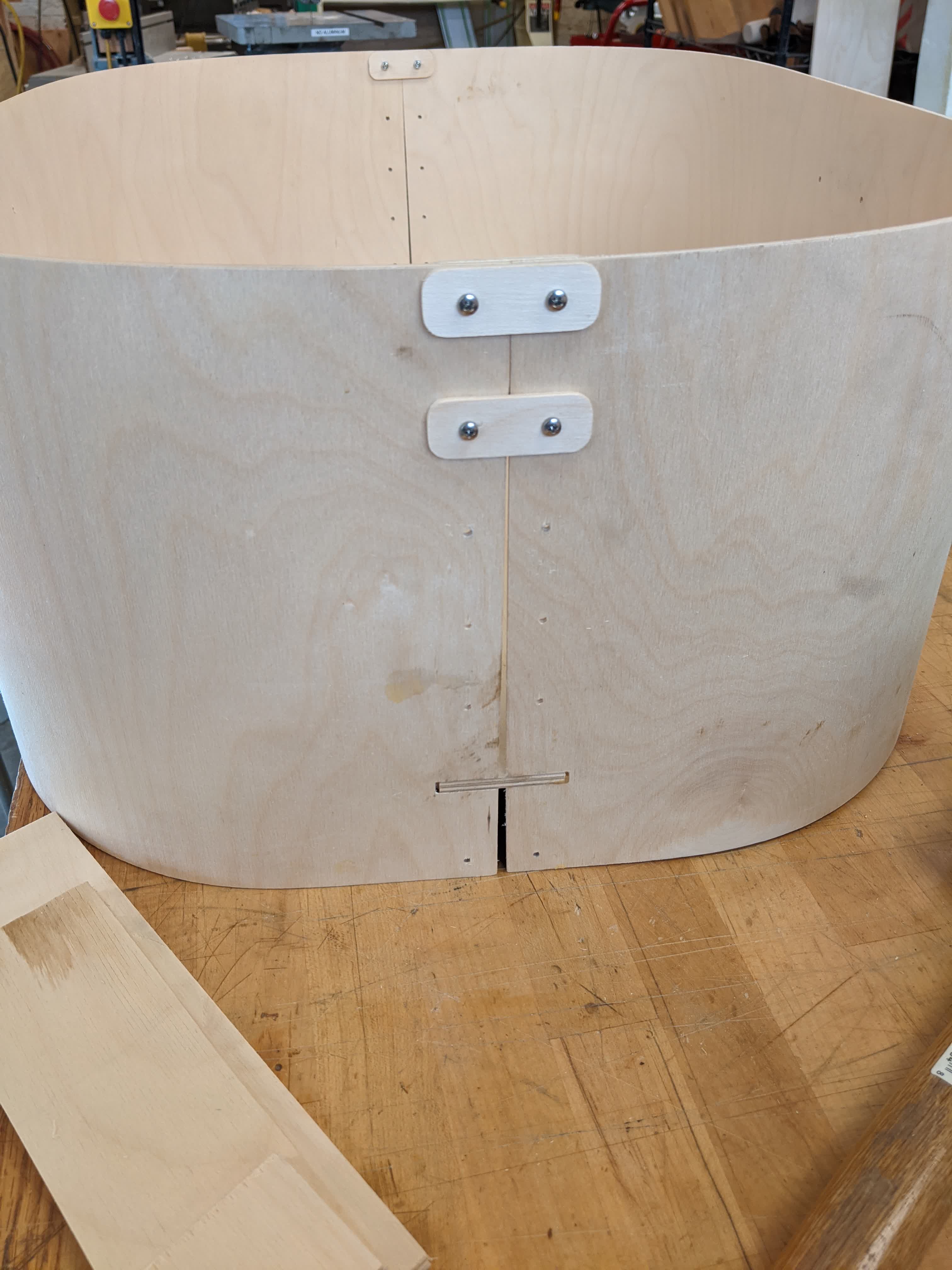
As you can see, I could fit the top 2 locks, but going down, they just didn't fit with that growing gap, and no, wood does not stretch.
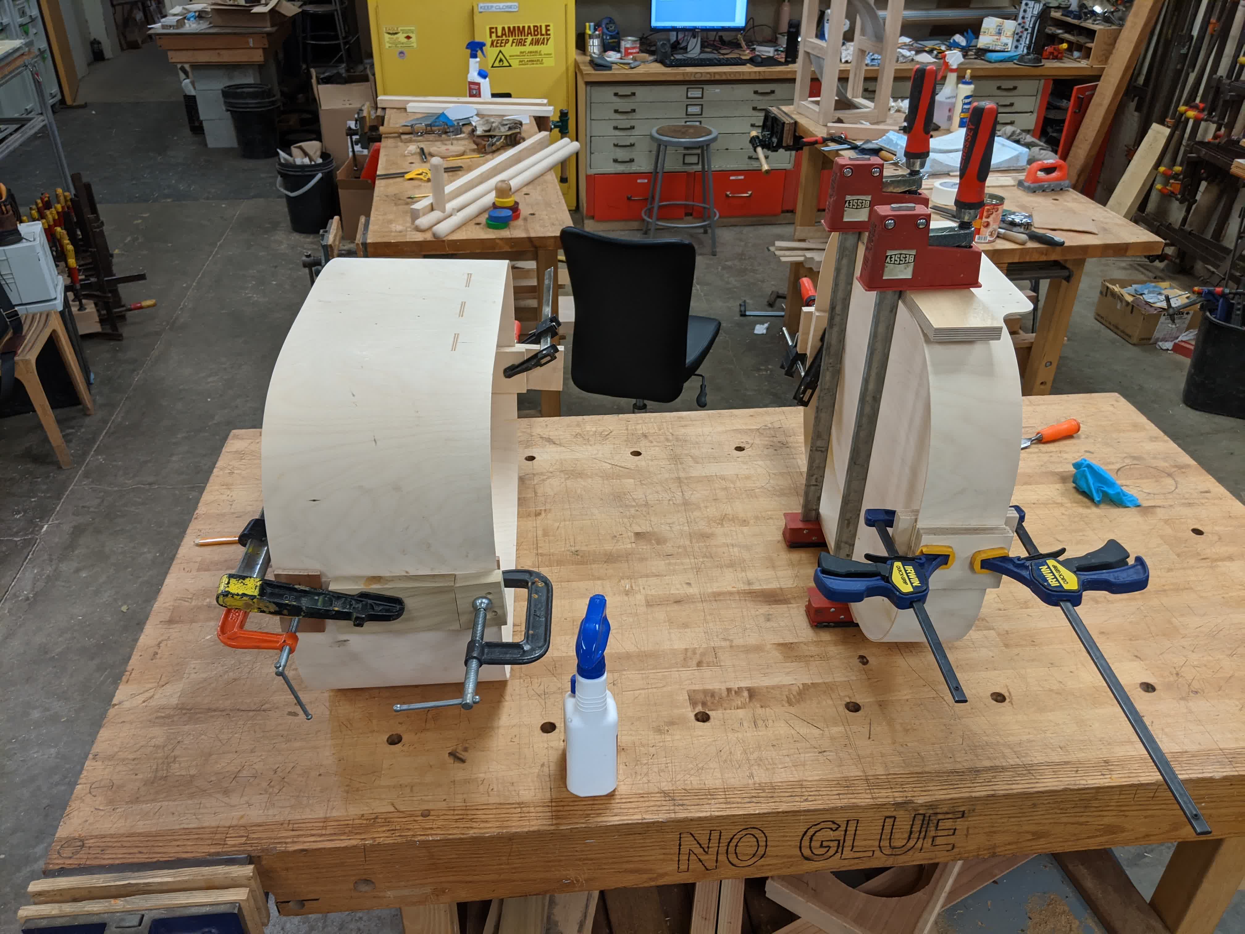
I decided I would fix this by cutting 2.5" wide pieces of the 1/8" aircraft ply and glue it on the inside and outside of where the two wall pieces meet both above and below the bed. This will add an extra amount of security keeping the walls together and the overall structure stable. I used the table saw to cut the 2.5" width, and a band saw to roughly cut lengths. I then glued and clamped as shown here:
Here are both the bassinet and the bottom pouch curing after applying the new glued lock strips:
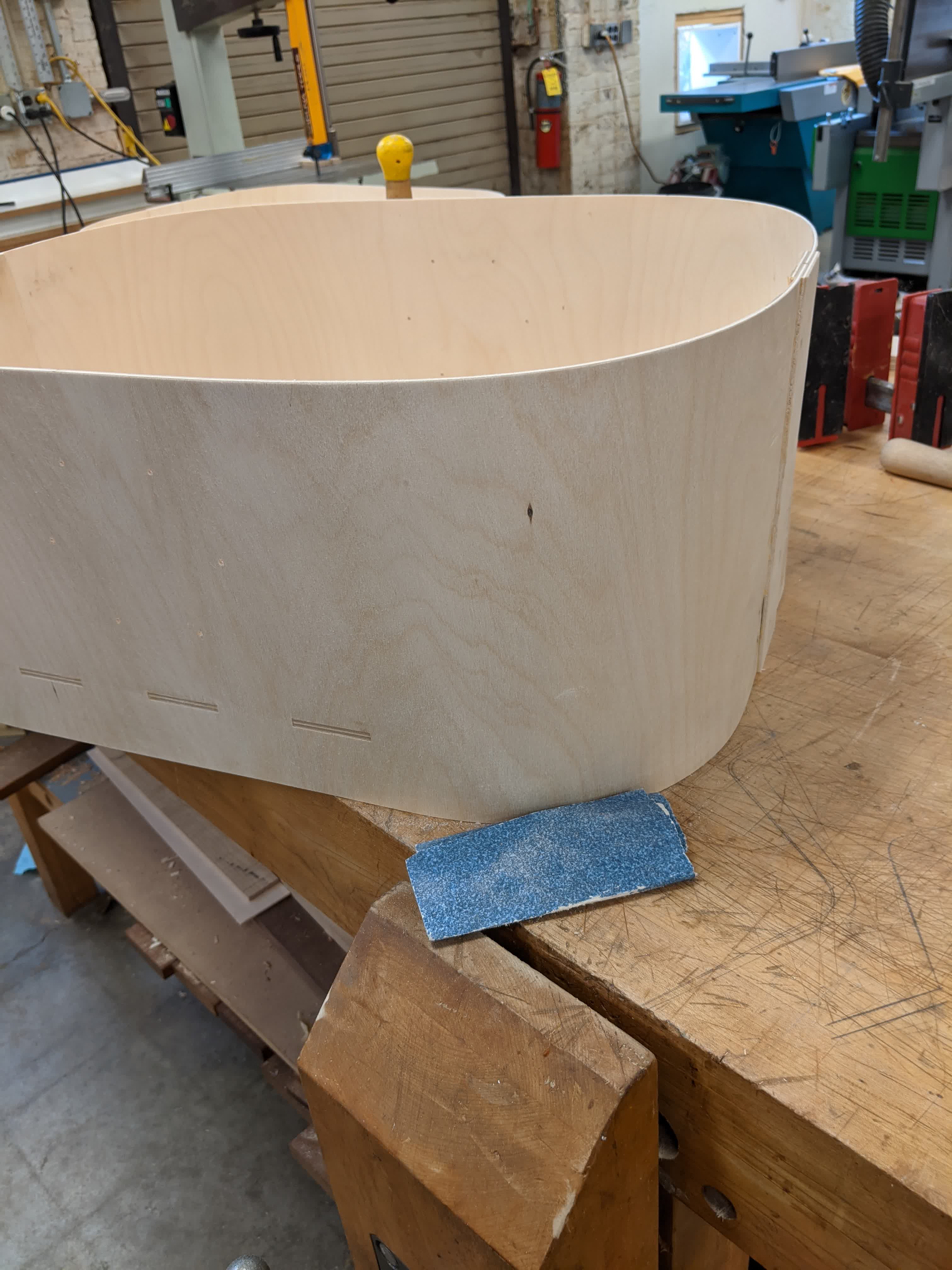
After that was left overnight, I removed the clamps and noticed smudges and excess glue that was squeezed out during the clamping process.
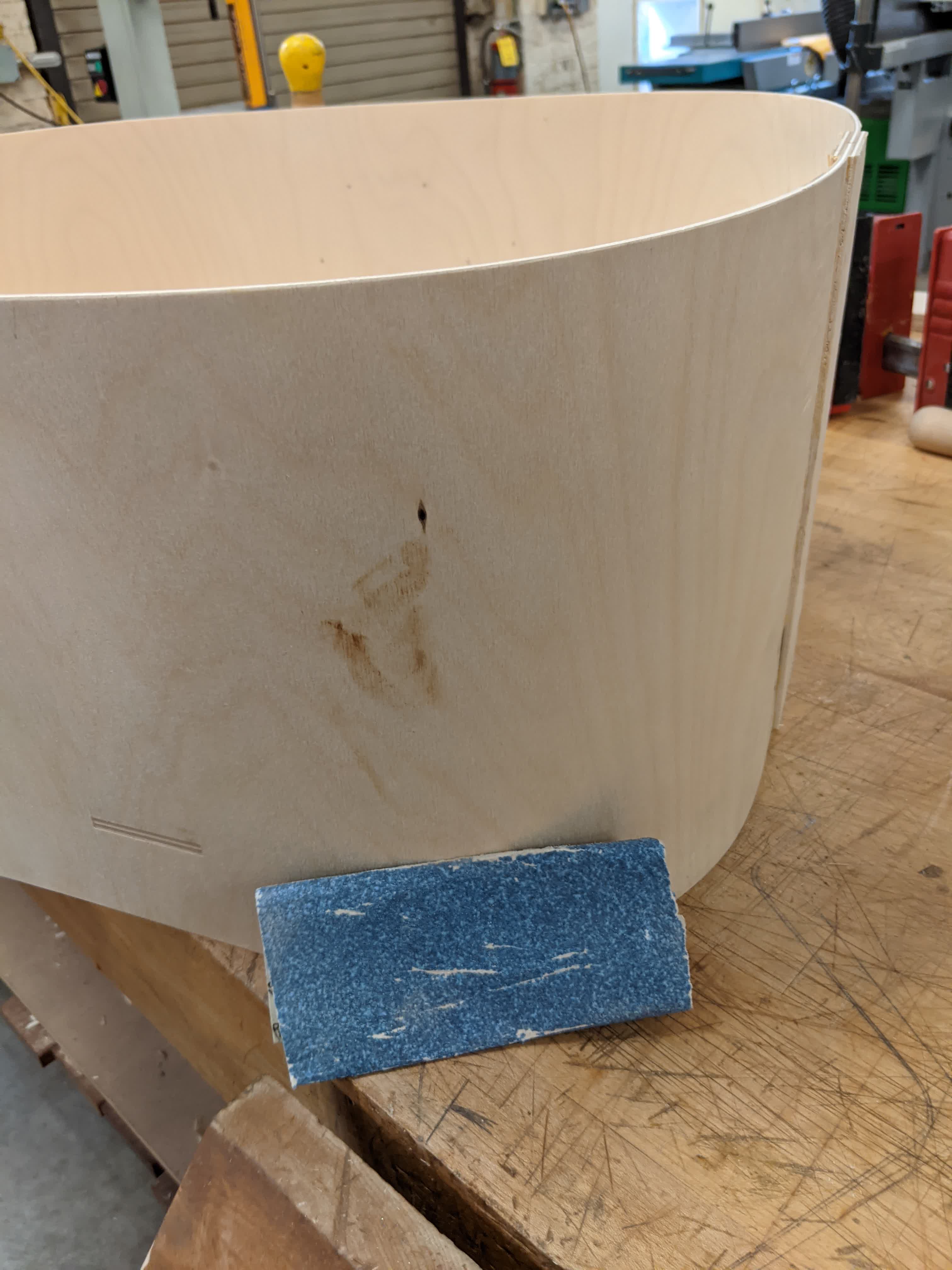
So I took some sandpaper and cleaned up all the faces, and used a chisel to remove the excess glue.
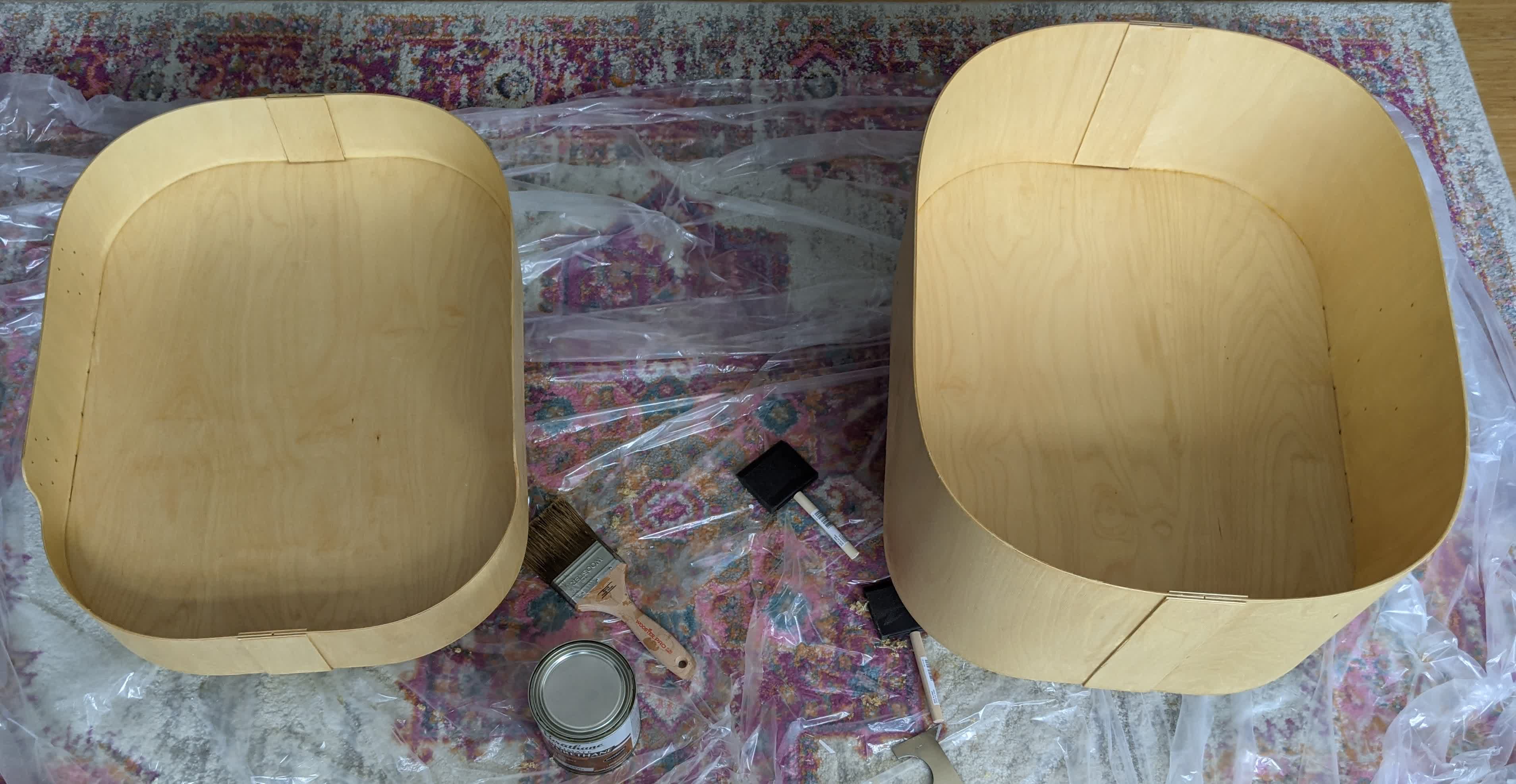
I then took them home and layed them out on a couple trash bags to start coating them with polyeurethane. My cat was curious as to what these new objects were:
This was a more involving process than I anticipated. I used a brush to coat, then a paper towel to wipe down and remove excess polyeurethane, then waited 6 hrs before recoating. I did this for all faces, 4 times, and I was done! Here are my beautiful bassinet and bottom pouch:
With these guys done and the legs ready, I just needed to wait on my 3d prints to put it all together.
3D Printed Parts - Joints
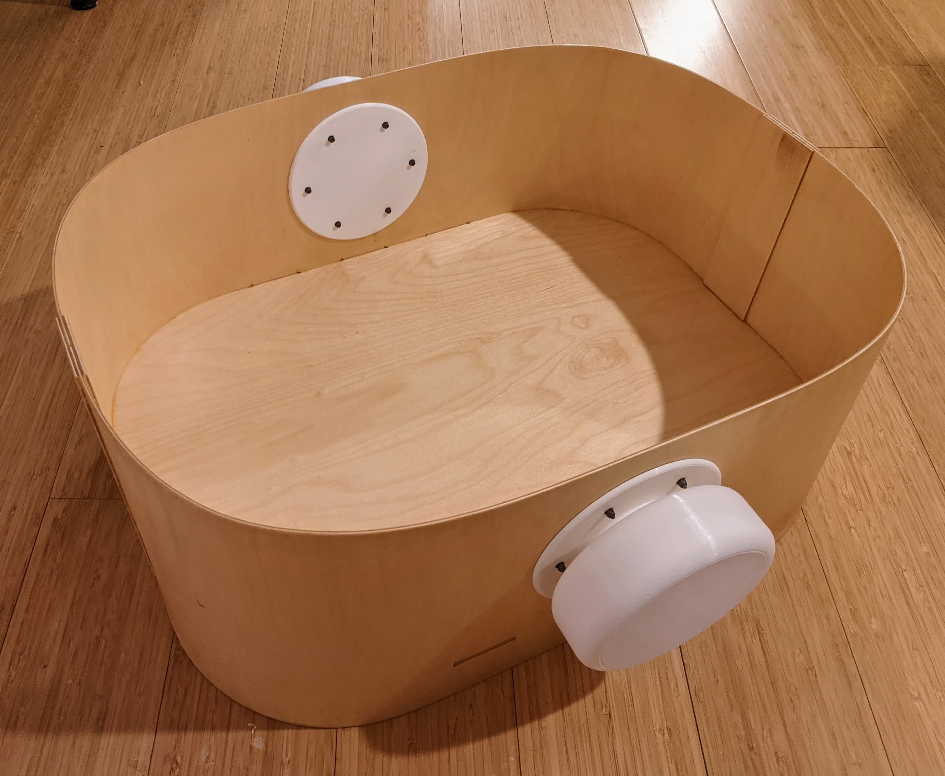
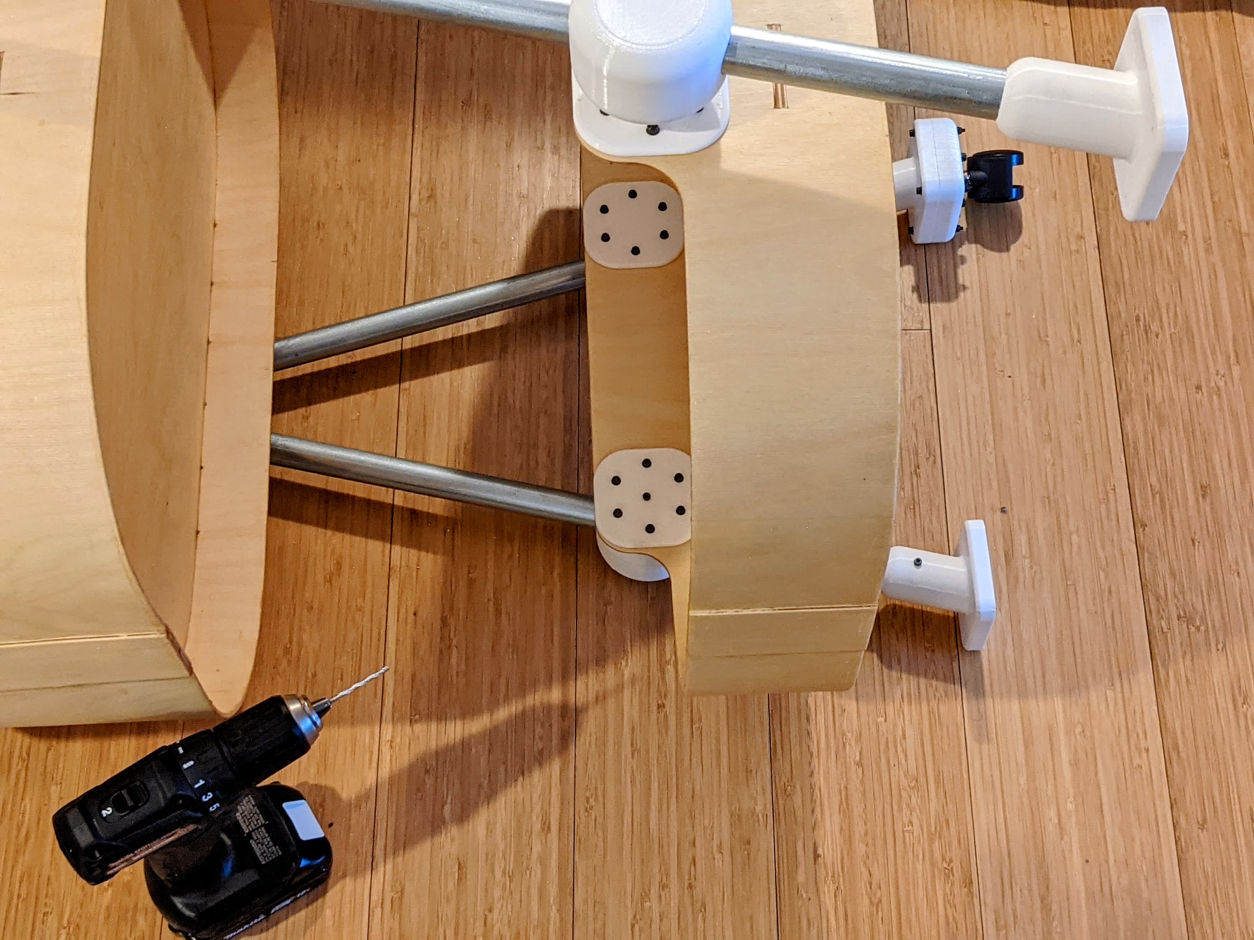
The hubs and their respective plates were mounted using 14mm long M3 screws, nylock nuts, and washers on both sides. Each hub required 6 sets of screws, nuts, and washers.Here is the bassinet with the big hubs attached:
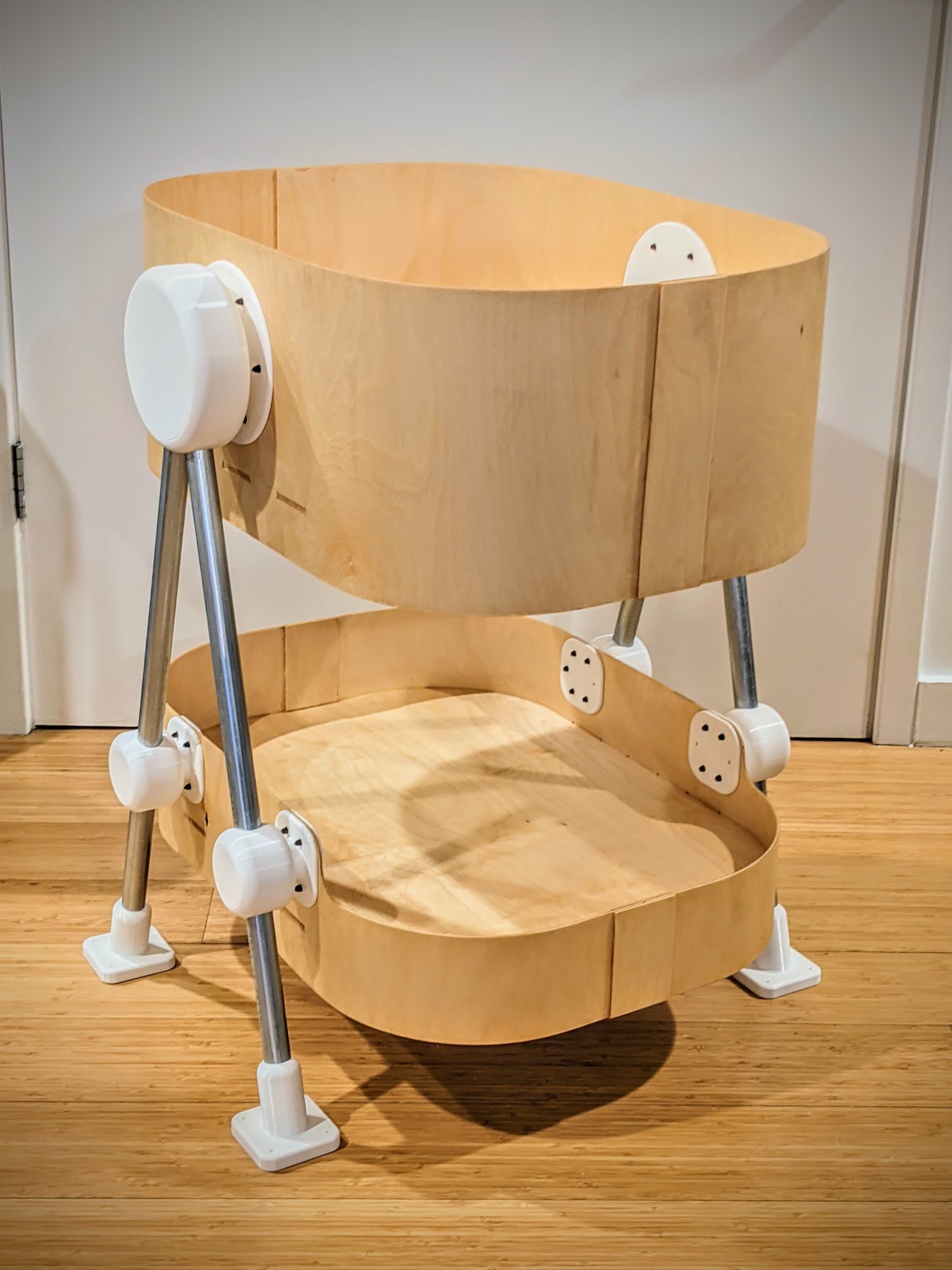
I went through the same process for the small hubs on the bottom pouch. I then slid the legs in place and slid on the leg sleeves. Here is the result:
Next was the motor assembly. Here is an image showing the motor and bottom clamp:
You can see that it is a good fit. I started by screwing in the motor mounting screws. Clamping to the leg sleeve comes later.
Here is a challenge that I had to deal with while screwing the mount to the motor:
It's probably a bad idea to buy cheap screws like this. I've never sheared off a screw head in my life. I did spend many hours trying to deal with this.
I uncrewed all the screws I could, and removed the top clamp. It took lots of effort to pull the motor out of the bottom clamp. I ended up drilling straight over the screw with a slightly oversized drill bit. This shortened the length of the sheared screw, which made it easier to pull out the motor. I then used pliers to unscrew the damaged screw.
This was a nightmare...
Finally, here's the complete motor assembly attached to the leg sleeve using 80mm M3 screws.
Moving on, here's the caster assembly:
With that, I assembled the caster assembly in the same way as the motor assembly, but used 50mm M3 screw. I then slid the sleeves on the legs and I was done.
Update: I discovered that the legs are a tiny bit too loose, as in they can rotate. Note that I have to use considerable force to rotate them, the fit is tight. However, they are technically not fixed from rotation. This could be problematic and could prevent the stroller from moving straight. I did some last minute improvising and used my hand drill to drill in a single hole through the leg sleeve and aluminum rod. The hole does not go all the way through and was done on the inside so it does not show. I then put a 25mm M3 screw in the hole and this fixes the sleeve from rotating. I also drilled a hole through the small plate, wall, small hub, and aluminum rod and put in a 45mm M3 screw. This will lock the entire leg from rotating. Here is an image of the screws placed into the hand drilled holes:
Hindsight is 20/20 and I should have considered this in the initial design.
Now that the assembly is done, I can move on to the electronics.
Electronics
Most of the electronics have been a work in development over the last several weeks. I was using the weekly assignments to explore what I can and can't do.I decided that I would work with the motors described above, as well as the the time of flight (ToF) sensor (VL53L1X). The idea is that I would control the motor based on the distance measurement of the ToF sensor.
Stage 1 - Moving in a Straight Line
The idea of Stage 1 is to use the time of flight board to network with a motor control board and control the motors based on the distance measurements.Board Design
The details of the time of flight board and my experience with it can be viewed in the Output Devices tab. Here is a footprint schematic of my board as a reminder/reference: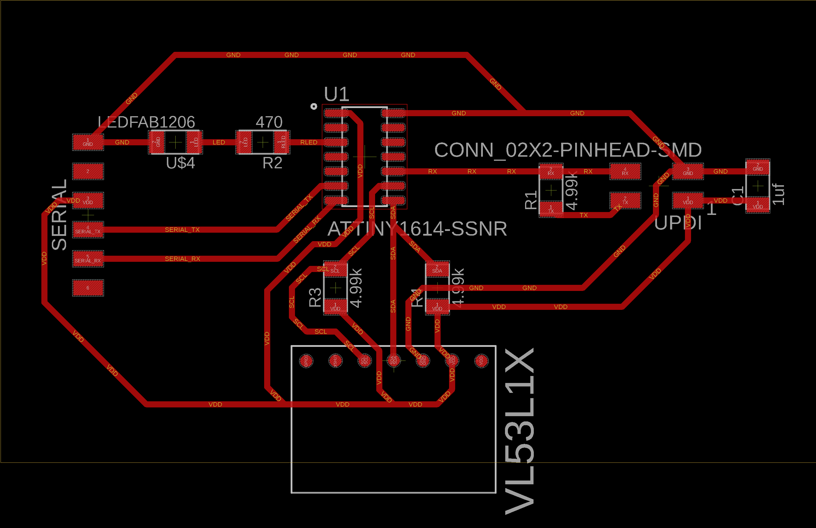
The VL53L1X is a time of flight sensor that comes on a carrier board made by Pololu. This board uses the ATtiny1614 to communicate with the VL53L1X using the I2C protocol. The SCL (clock) line goes to pin 9 and SDA (data) line goes to pin 8. It only needs to connect to power and ground in addition to that. Note I do have a pullup resistor for the I2C communication, but discovered later that the carrier board has built in pullup resistors and that the ones on my board were not necessary.
The motor control board was actually the ATtiny3216 breakout board I made in Networking & Communications week. Also as a reminder, here is the motor control board:
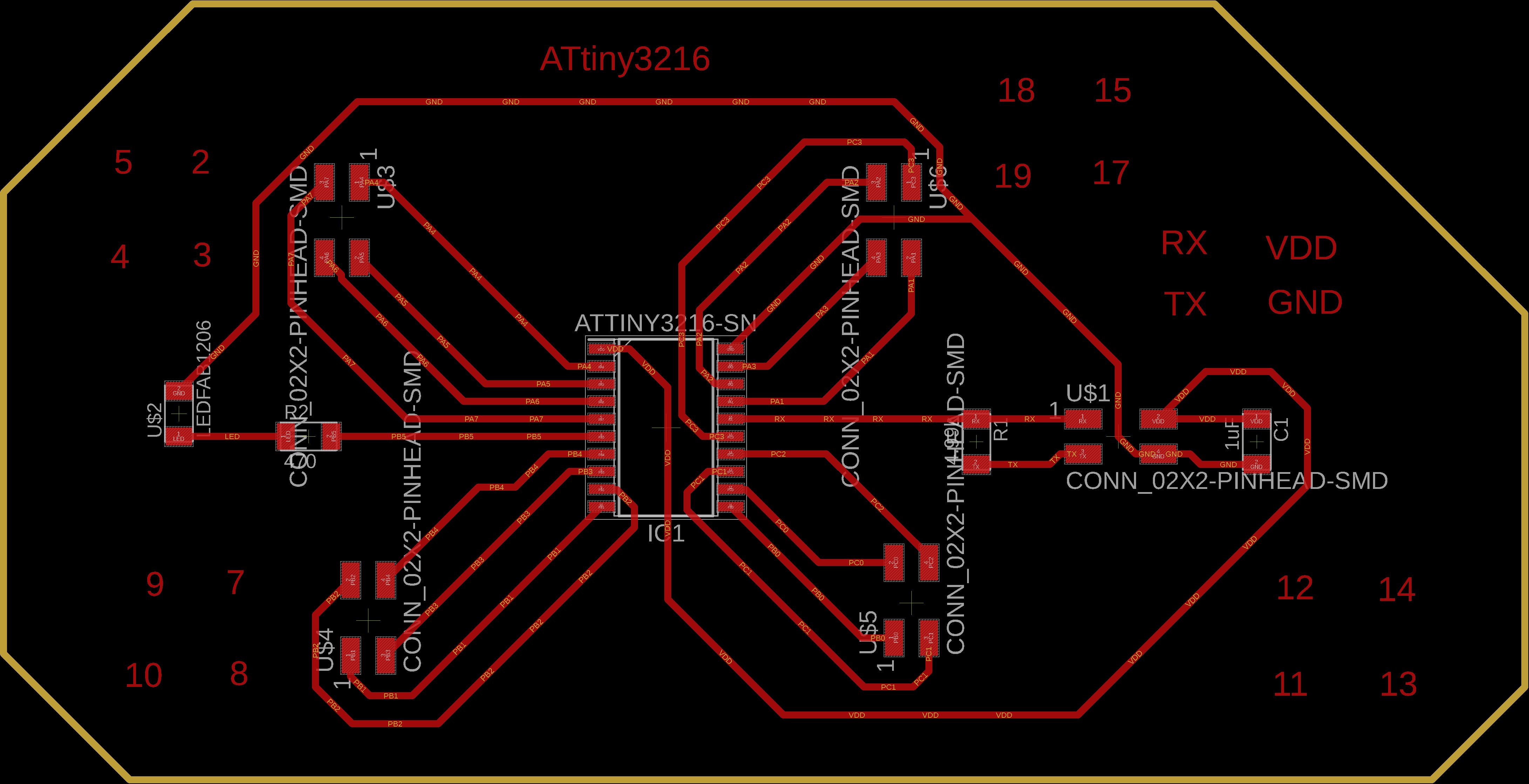
I described then that I was connecting a dual channel h-bridge to this board using jumper wires.
Note that I don't need a voltage regulator on my AT3216 board (like what I did for the light controlled motor board in Output Devices week) because it is built in to this carrier board. As an initial test, I used this board to network with a motor control board using software Serial. The actual Serial pins (RX on pin 6 and TX on pin 7) from this board go to the software serial pins that I designated on the motor control board (crossed, ie TX to RX). The details of networking can be viewed in detail in the Networking & Communications tab. Basically the ATtiny1614 reads the measurements that the VL53L1X provides, and lobs it off to the motor control board.
As shown at the bottom of the Networking & Communications assignment, I was having an issue with bits getting chopped off during communication with both boards. This is problematic because the motors will rely on these measurements when deciding when to move and in which orientation to move. When reading the VL53L1X measurements from the ATtiny1614, I get very consistent measurements, give or take a few mm of noise:
However, when these measurements were being sent to the motor control board, I noticed bits getting chopped up, for instance, if it was reading values around 1975 mm, the motor board was receiving things like: 1975, 1973, 1978, 197, 1976, 1, 1974, 1973, 19, etc...
So I wrote a function, with Clavin's help, on the motor control board that filters out this data. In summary, it looks at 3 incoming measurements, and says that if they are not within 50 mm of each other, then don't store that data, and if they are, then store the latest data point. Here is a video taken from the motor control board where the left column is the incoming data from the time of flight board, and the right column is the filtered data:
With this, the motors respond to changes in distance a bit slower, but are definitely moving more smoothly, reliably, and this takes care of the motor stuttering problem.
Testing
In Networking & Communications tab, I show all the connections and resulting behavior, with the motors on the table. Now the motors are assembled on the stroller. For initial testing, I simply flipped the stroller upside down to check that everything works.Power Supply
I figured out my uneathered power supply issue, ie getting rid of the 5V USB power and 12V wall plug. I am using 3 AA batteries in this battery holder to supply 5V to the motor control board and the time of flight board. Here is an image of the battery holder with batteries after I soldered the leads to female jumper connections: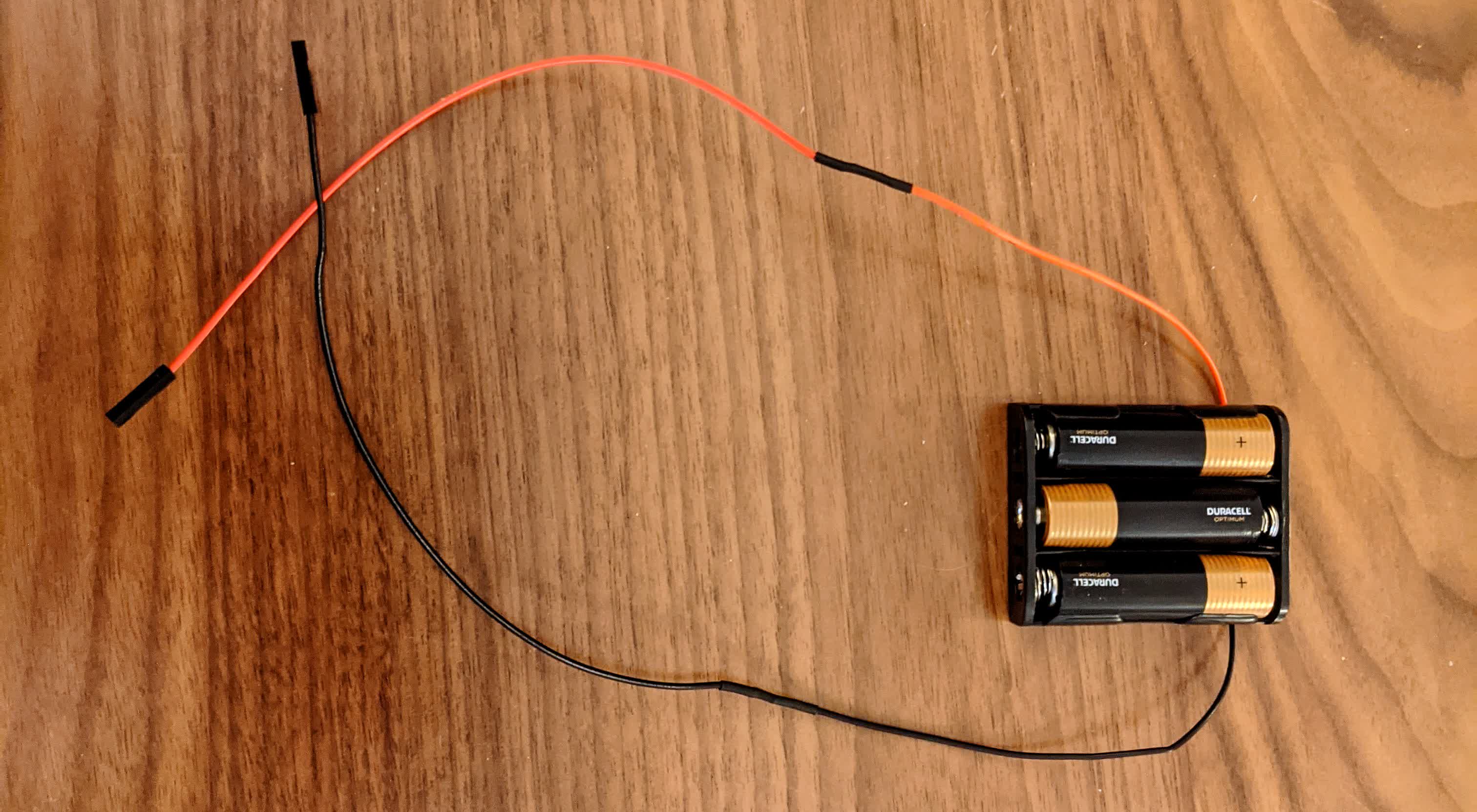
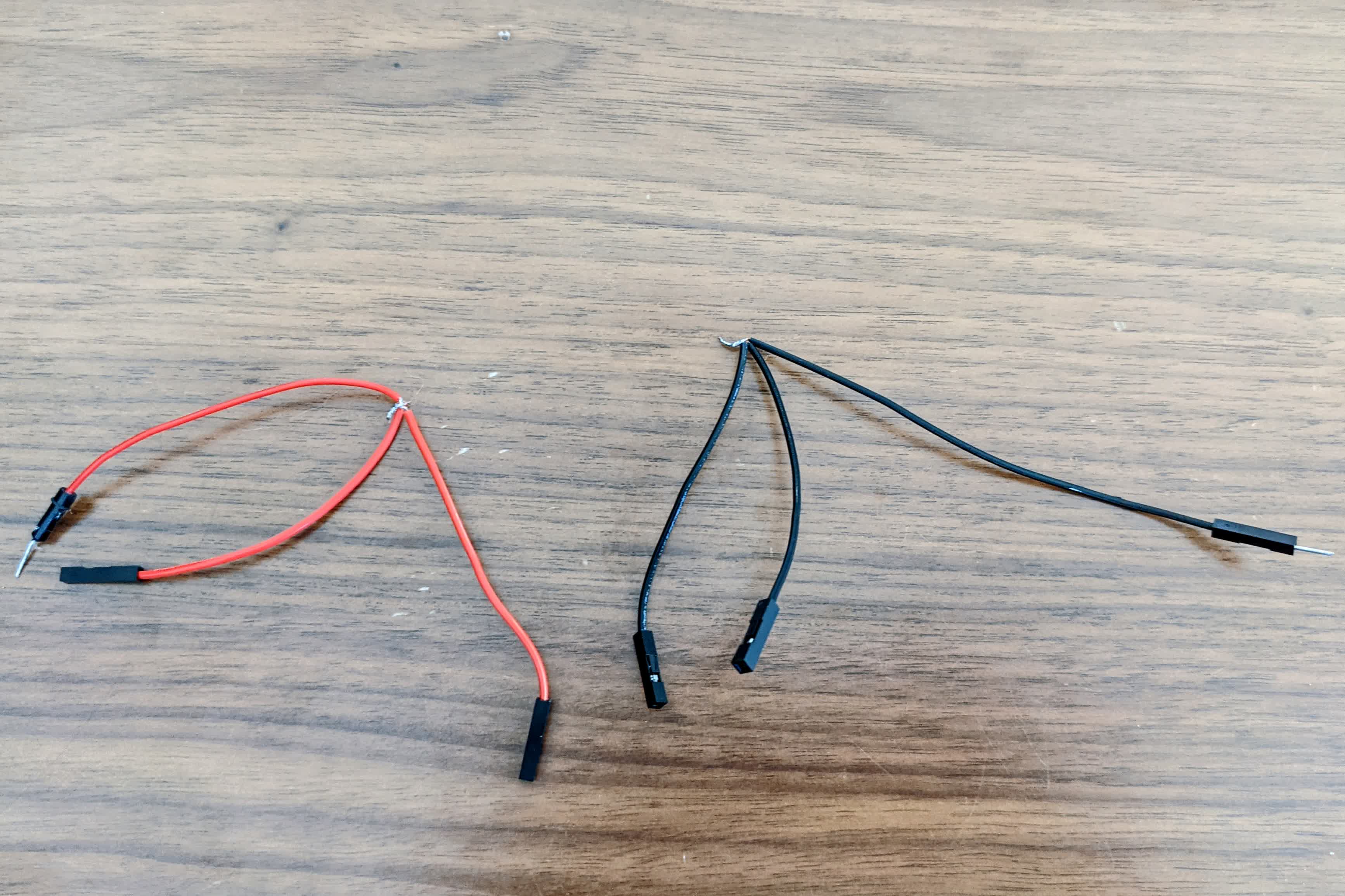
I then cut and soldered a couple jumper wires to form a triple junction, with 1 male connection to fit in the battery jumper, and 2 female to fit in the board VCC pins. I did this for power and ground:
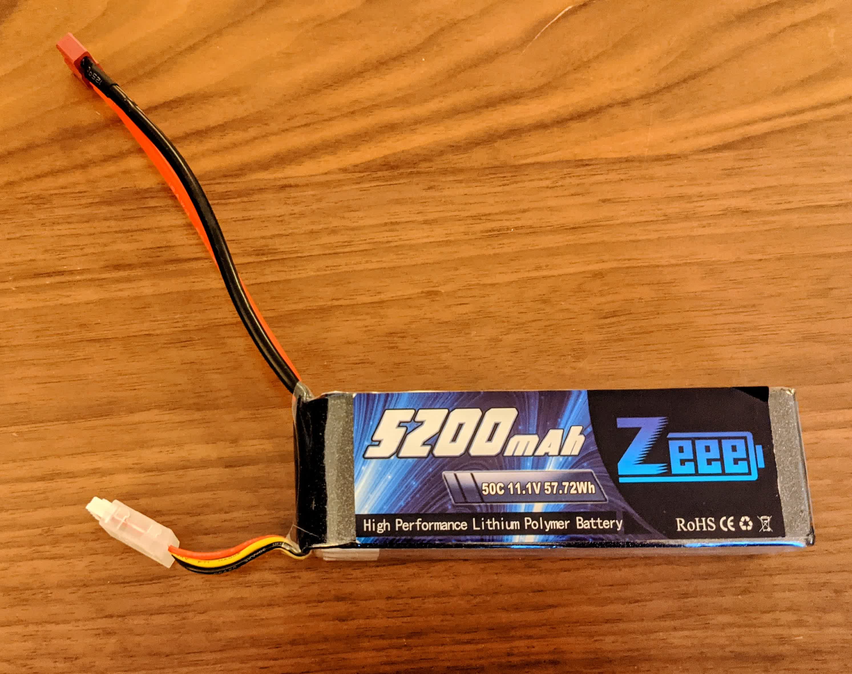
To power the motors unteatherd, I resorted to a lithium polymer battery. I learned about the power requirements and current discharge rate. I was using 12V motors that can draw up to 6A each, so I got a 5200 mAh 11.1V 3S 50C LiPo battery. 3S means that it is 3 cells, 3.7V each, in series. 50C is the discharge rating, which translates into 50*5.2Ah=260A. This is definitely overkill as I will not need to draw this much current. I also got an appropriate charger that can balance charge, make sure the cells get charged evenly, as well as storage charge/discharge. Apparently, LiPo batteries need to be in constant use, either charging or discharging. They don't like to be sitting around, which may lead to shortening of life and/or swelling and blowing up. They also should not be left sitting fully charged, nor completely drained. It is also important to make sure they never fully drain, because they might not be able to charge after that. I also learned they typically have a 1000x charge discharge life, and to make sure they are completely drained when disposed of at a designated facility. Here is an image of the LiPo battery I am using:
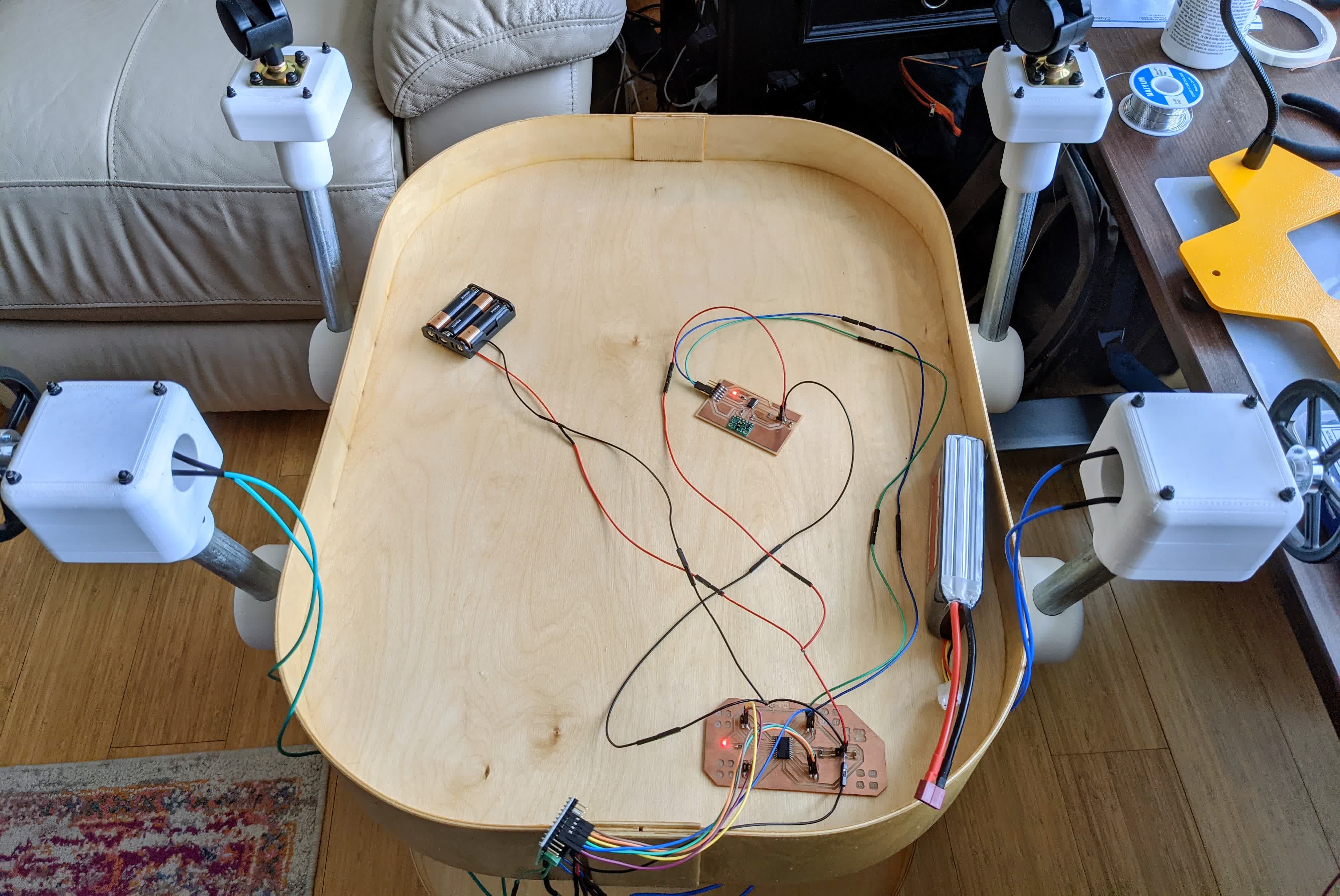
Finally, I ordered male T-plugs to plug into the LiPo battery. I soldered a thinner wire onto the bare leads to fit into the h-bridge screw terminal to supply voltage to the motors. In the below image, you can see going from bottom to top, the dual-channel h-bridge, the motor control board, the lipo battery, the time of flight board, and the AA batteries.
Programming
Most of the programming was done and is described in the Networking & Communications tab. I programmed the motor board to take the filtered distance measurements from the ToF board, and perform the following actions:-if the distance is less than 0.5 m, move away from me
-if the distance is greater than 1m, move towards me
-if the distance is in between, then break
This allows me to take my stroller out on a stroll in a straight line, maintaing a specific distance away from me. The sketch for the ToF board is here, the sketch for the motor control board is here. In addition, I made a motor control sketch where I am simply checking the orientations that the motors go so I can know what exactly is "towards me" and "away from me" here. This is important because the motors only know how to go clockwise, counterclockwise, coast, and break, and they are mirrored, so to go away from me, one would have to turn clock wise and the the other counter clockwise.
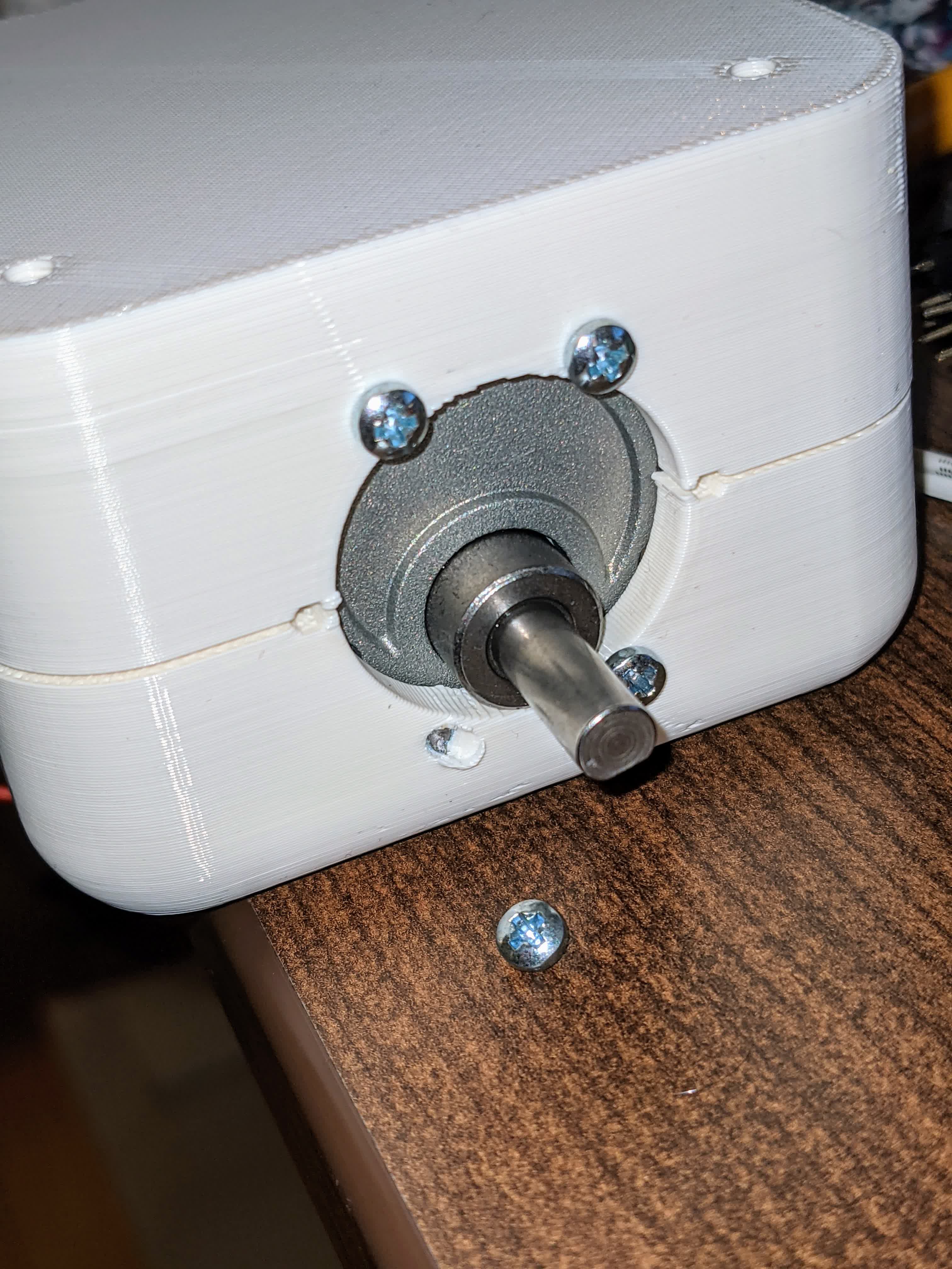
Damaged Motors
I did run into one problem throughout all this. After plugging the motors in, I discovered that they were not moving. They were moving before I assembled the motor clamp assembly, and now they were not moving. Here's a video showing this:It turns out that the screws on the front face, which hold the motors to the clamps, are actually blocking the internal gears from turning. I contacted Pololu about this, and they told me the screw holes on the motor face should not be penetrated more than 3mm. I was pretty frustrated that they would not make this more clear. It turns out they had a really tiny footnote burried in the datasheet stating this. Backing out the screws allowed the shaft to rotate, but there was a distinct clicking sound with every revolution, meaning that the gears were damaged. They were kind enough, however, to send me replacement motors which I swapped in. The wall thickness of the front face of the clamp is 5mm, so I used 8mm M3 screws with 1 washer to make sure the ends of the screws are not hitting anything internal, but are definitely screwed in to the motor.
Overall, I was surprised at this poor choice in motor design by Pololu. In the future, I would probably check for a bottomed hole, or at the very least, confirm with the motor supplier how far screws can go in if they are open to the internals.
Actual Testing!
After verifying everything working upside down, I flipped the stroller right side up. I stored the h-bridge, motor control board, and batteries in the bottom pouch, and used a few jumper wires to extend the time of flight board to the top of the stroller.Here it is, finally alive and in action, maintaining a distance away from me, moving back and forth:
You have no idea how happy and excited I was at this moment (my face was cut out of the video). This was great, but to make it more practical, I needed to find a way to steer!
Stage 2 - Moving in a Straight Line with Steering Capabilities
For this stage, I decided to add 2 more ToF sensors, as well as make a new board that can accomadate I2C communication better.Board Design
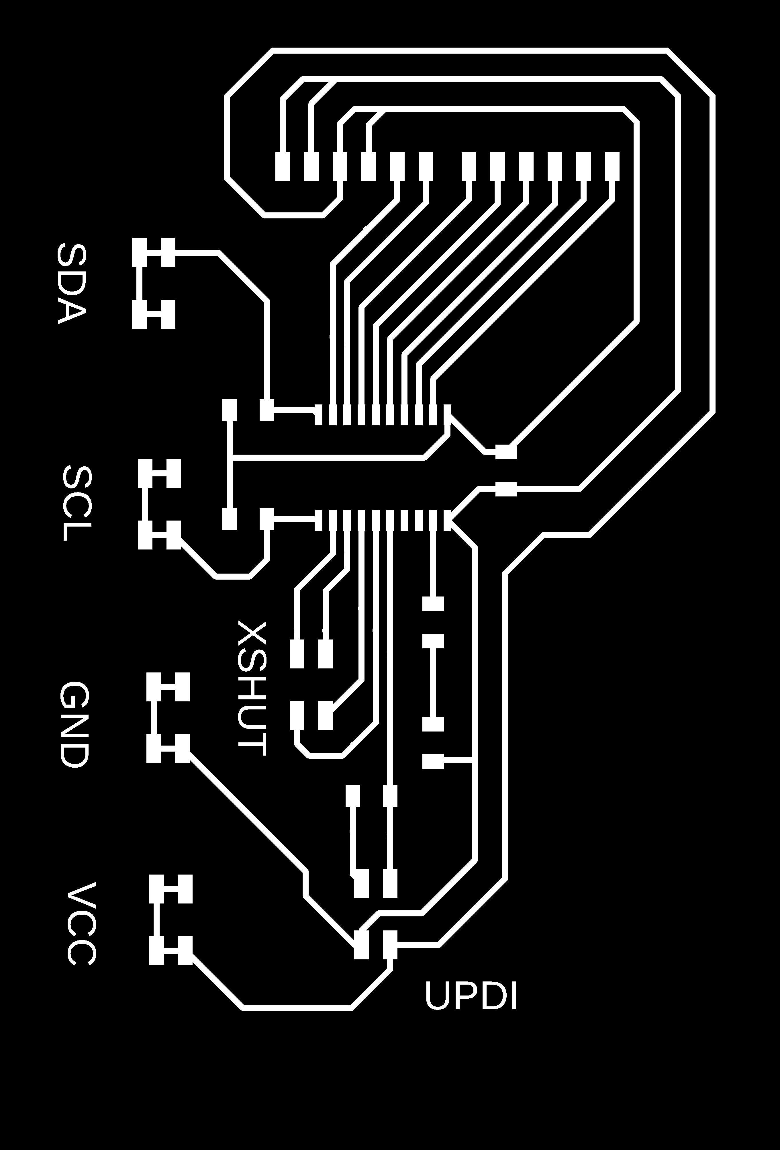
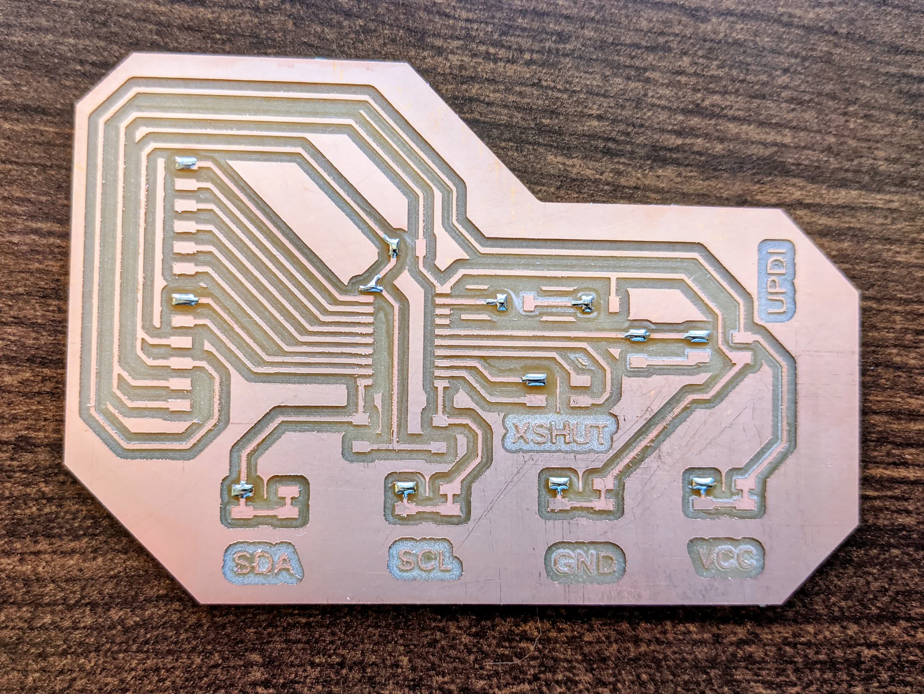
Here is a schematic of the board: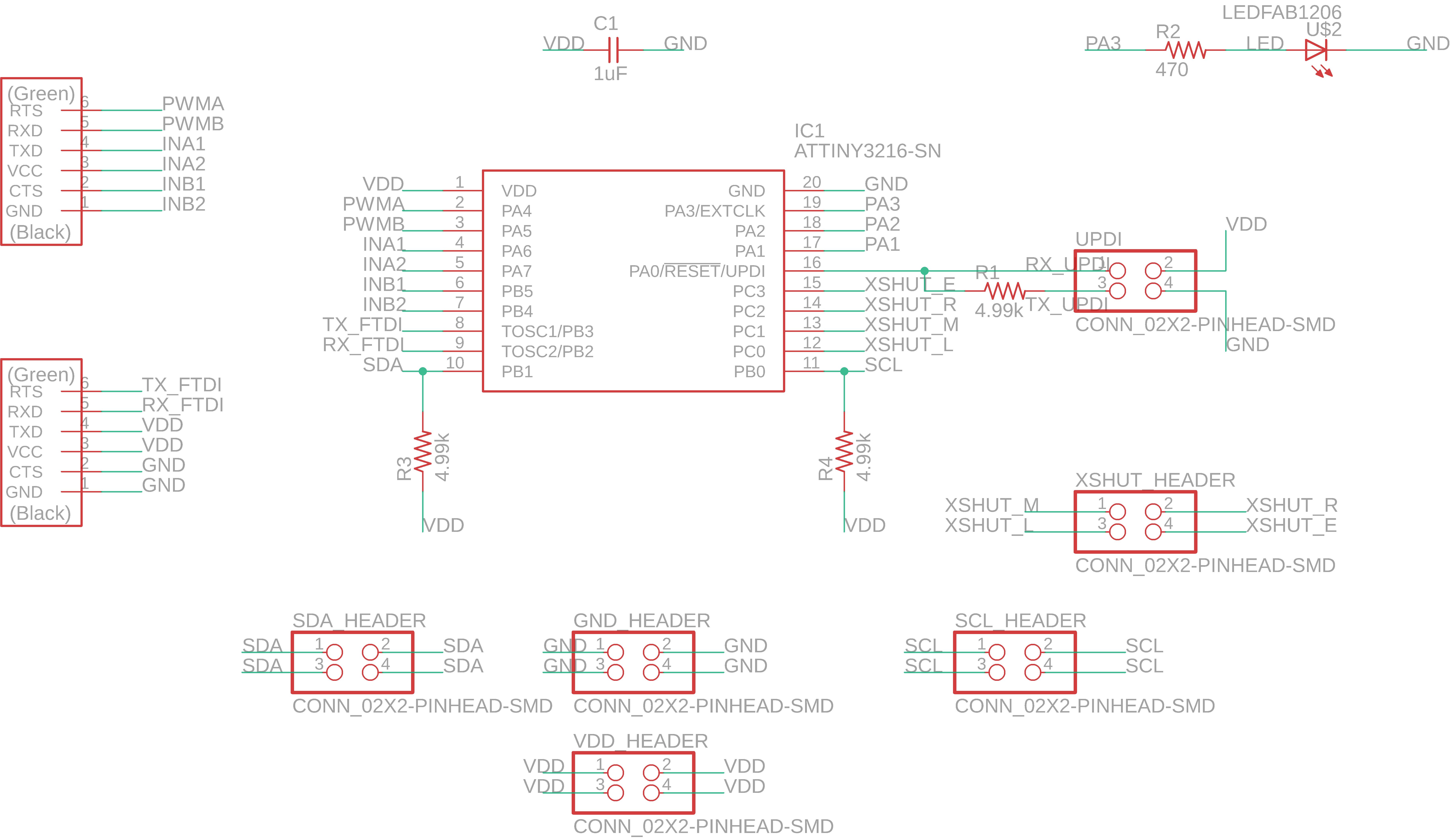
and here is the layout:
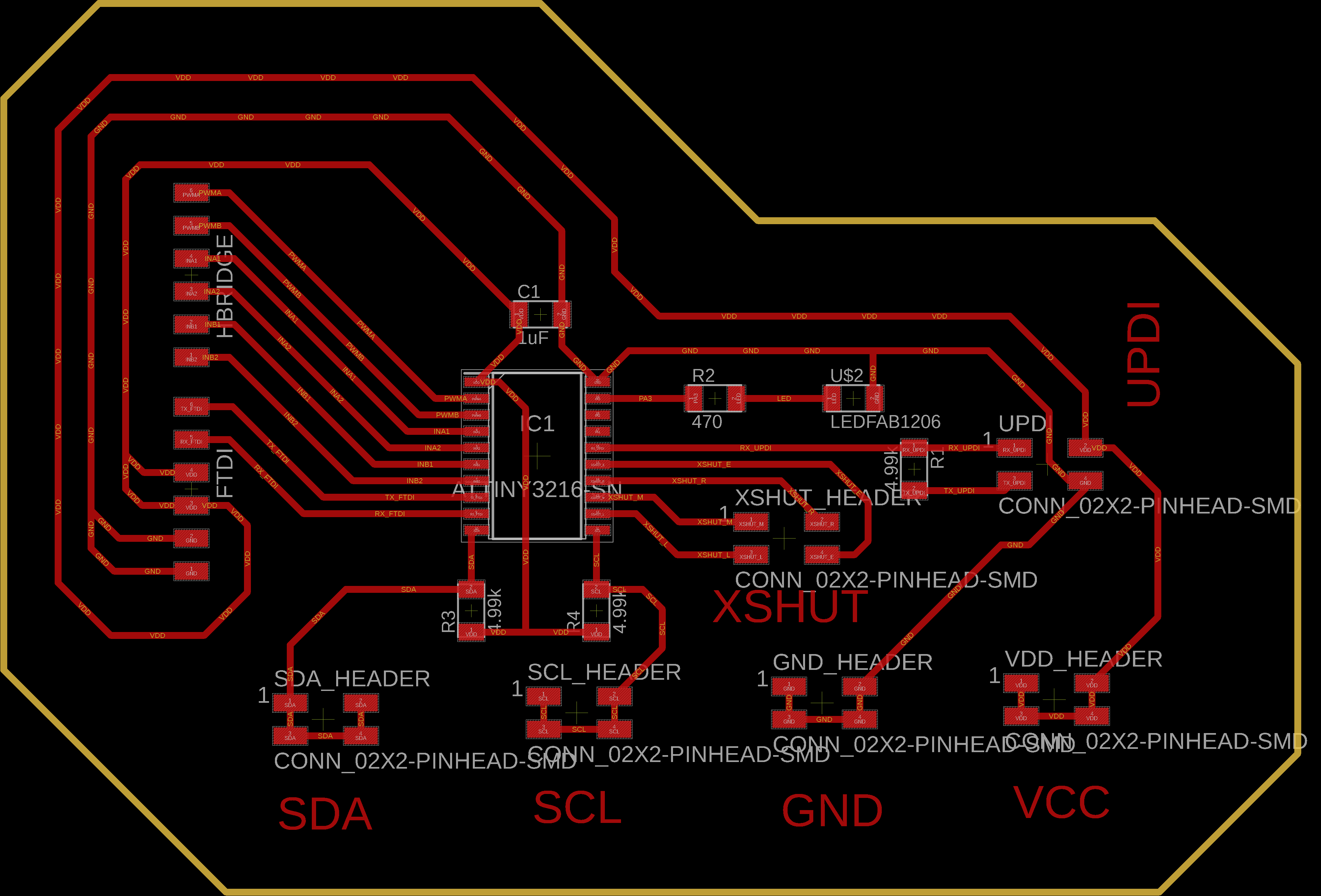
It took me a while to figure out how I2C communication with the VL53L1X works, but I did. I basically can have all the sensors connected to the same SDA and SCL pins on the microprocessor. So I made the SDA and SCL break out into 2x2 pin headers. I also added 2x2 pin header for power and ground. Finally, these sensors are equipped with an XSHUT, a pin that is in an active-low shutdown input that the carrier board pulls up to VDD by default. The idea here is that I can connect each sensor XSHUT to an indiviual pin on the microprocessor, and give it a LOW to power down, and then a HIGH to power up. To use multiple VL53L1X's, I'll have to power them all off, assign each sensor an address, and then power them on one by one. Then I can know which reading is coming from which sensore. This board is equipped to hand 4 sesnors, but I'm using 3 for this project.
In addition to its I2C tailoring, I decided I would cut out the networking and connect the dual-channel h-bridge to it. I am still going with breakout pins because of the stroller layout, so the h-bridge will also connect using wires.
Update: Although I could have connected each sensor to each pin independantly, I didn't to limit the number of wires going from the top bassinet to the bottom pouch. Given that they all connect to SDA, SCL, VCC, and GND, I made a single cable with junctions connecting to each sensor and this board. The exception is for the XSHUT pin, where each sensor is connected with its own independant wire to its designated XSHUT pin on the board (ie the left sensor goes on the bottom left pin on the 2x2 pin header, etc).
I cut the traces using 0.004" cut depth, 10 offsets to make my life a bit easier when soldering, and at 2.5 in/s.
I cut the outline using 0.01" cutdept up to 0.058" (the thickness of the board), at 2.5in/s.
The gcode for the traces is here, and the outline here.
Here is the board after milling:
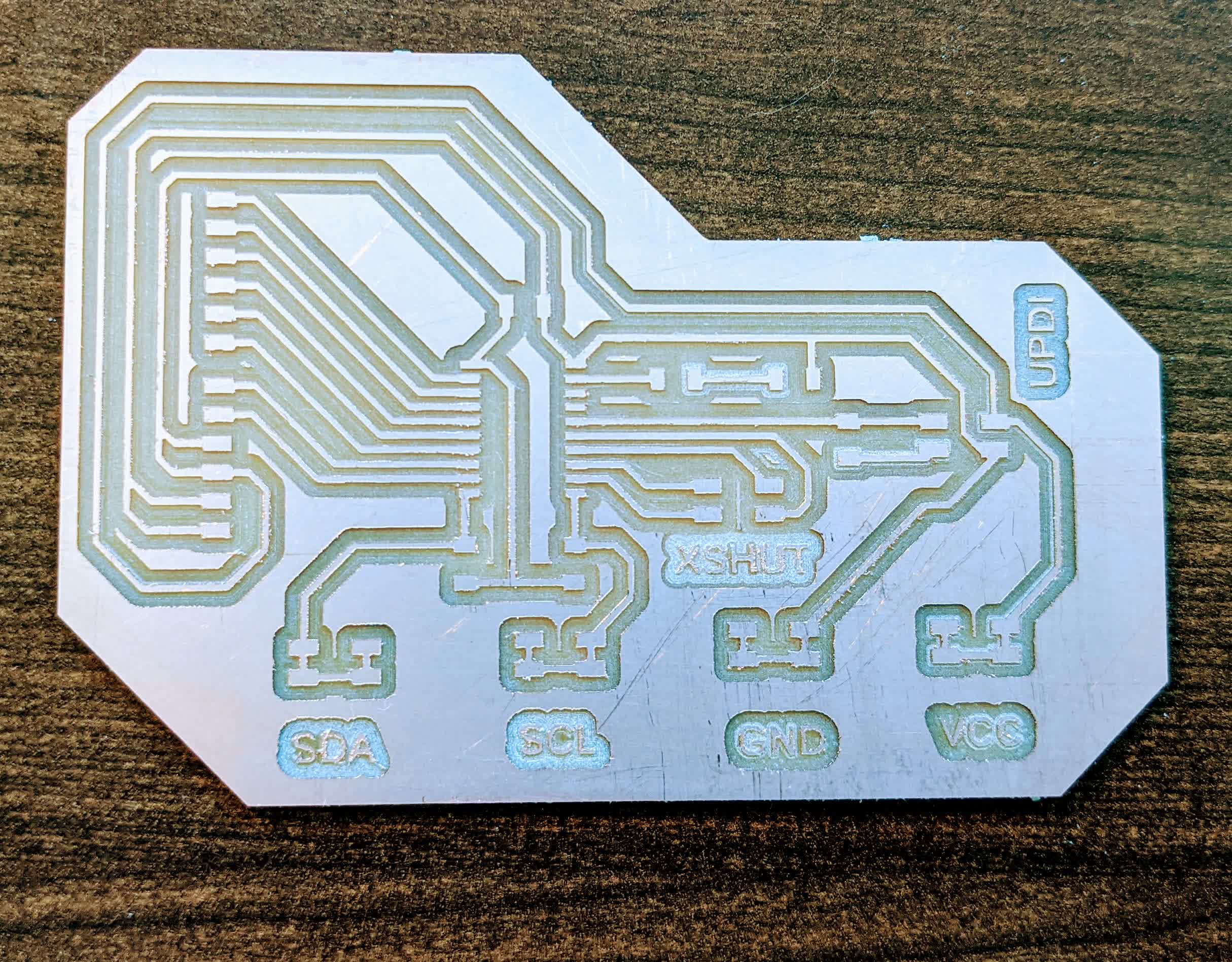
The scratches were from the Gojo I used to clean the board prior to cutting as well as from the metal ruler I used to clean off the burrs after milling.
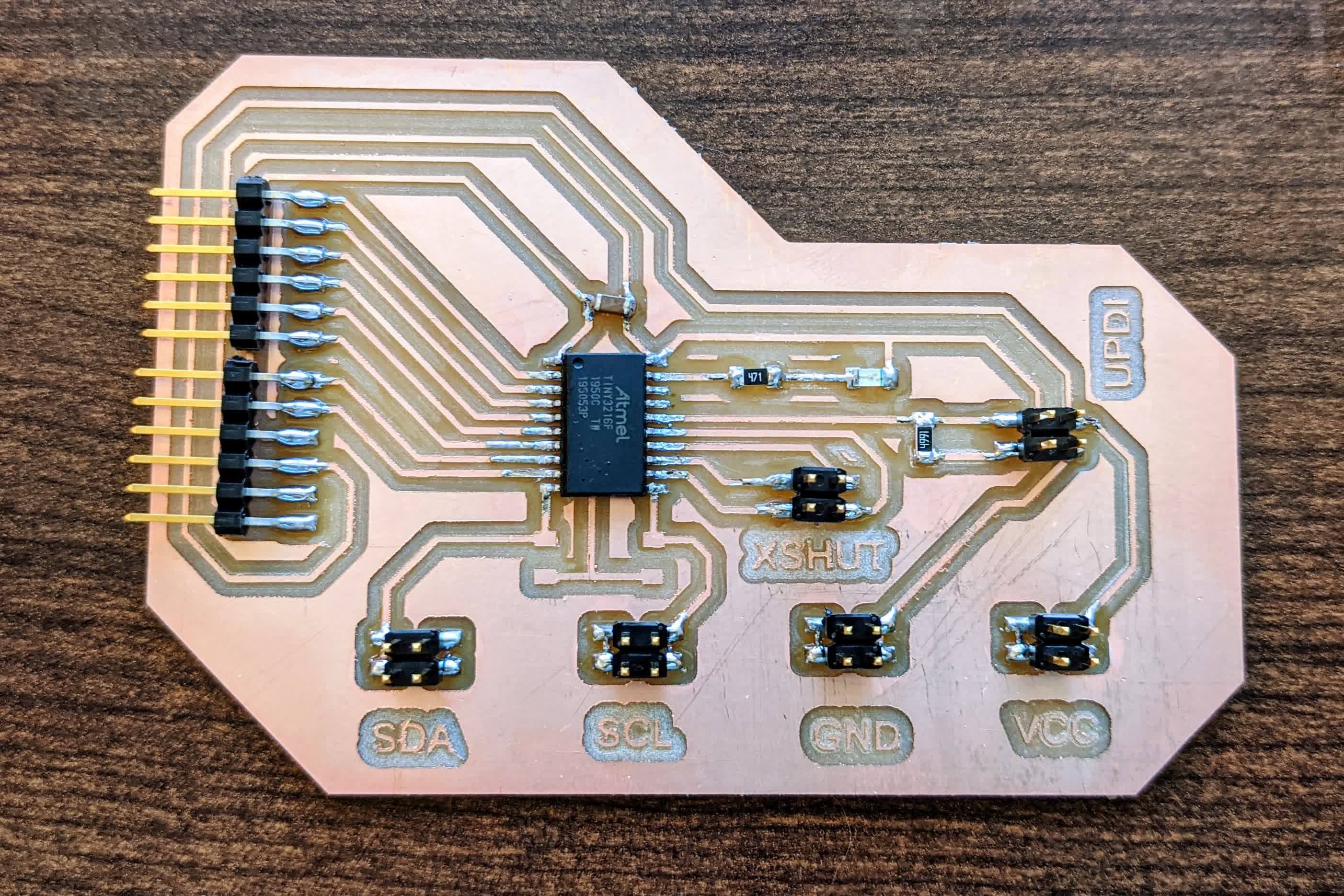
As usual, I lay out all the components before soldering:
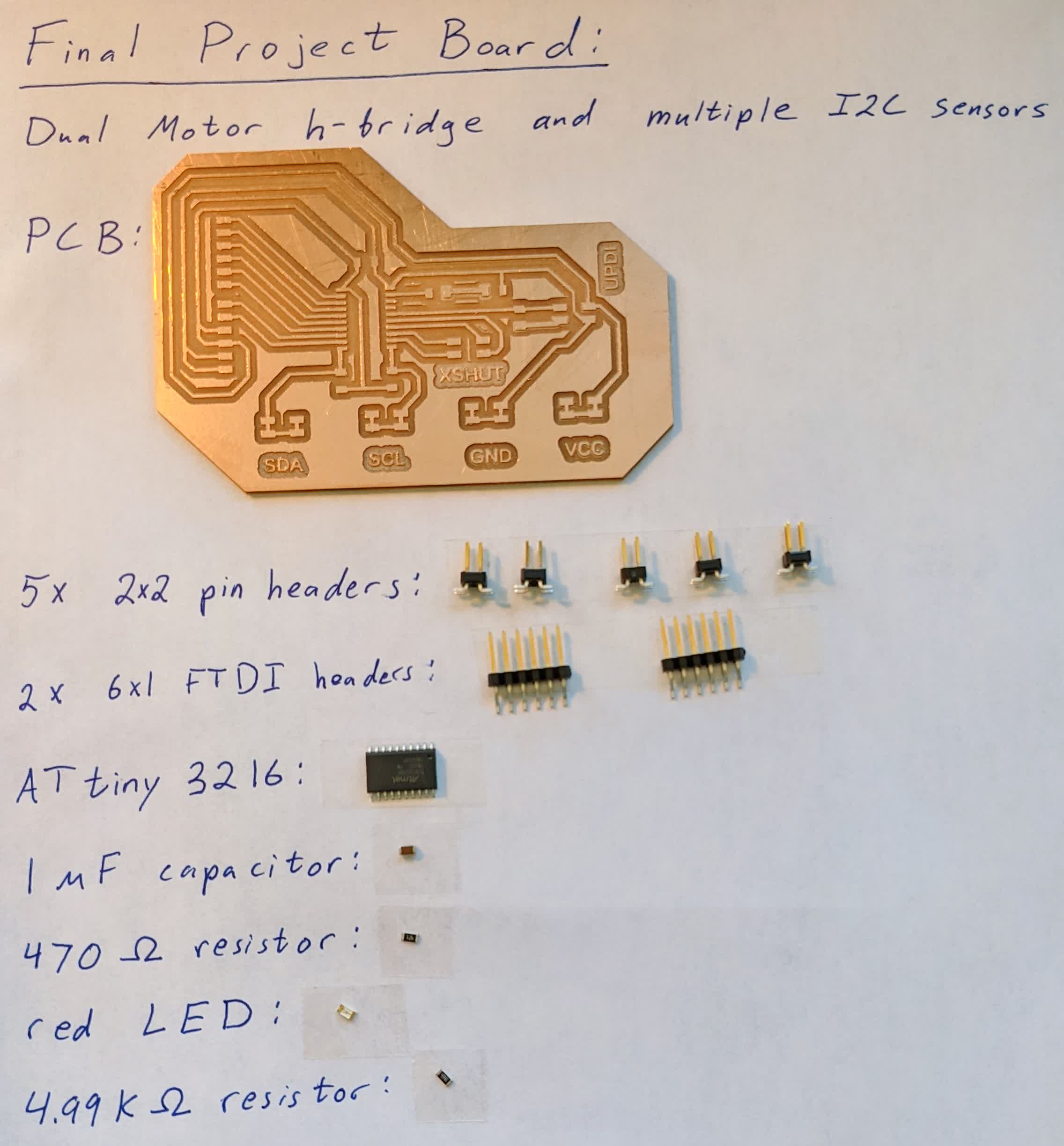
Note, I said 5x 2x2 pin headers, but I actually needed 6x. I am showing this again because of how helpful it is, but it is always good to dot 1 pad of each component first:
Here is the final result:
Programming
I know that there must be a better way to do this, but I was running out of time and this is just a proof of concept. Here is what I programmed the board to do:-If the distance from the middle sensor is less than 0.2m, move away from me. This makes it move forward when I move forward.
-If the distance from the middle sensor is greater than 1.5 m, come towards me. This makes the stroller come to me when I am too far.
-If the distance from the middle sensor is in between 0.2m and 1.5m, then break both motors.
-If breaked AND the distance from the left sensor is less than 0.2m, then keep the right motor breaked and move the left motor away from me. This steers the stroller right, as if I am pushing it from the left side.
-If breaked AND the distance from the right sensor is less than 0.2m, then keep the left motor breaked and move the right motor away from me. This steers the stroller left, as if I am pushing it from the right side.
I was overwhelmed by all the components at play here, so I took things one step at a time. I plugged in 1 sensor to the board to check that it was working. I then plugged in 2, and then 3. Here is my code to test multiple sensor readings which spits out the readings from all the sensors connected to the board onto the Serial monitor. I then unplugged the sensors and used the Motor control test code I ran before to check that the board can run the motors.
Note on GROUNDING: I did run into an issue here, a power issue. The hbridge is connected to the LiPo power and ground, and the board is connected to the AA batteries power and ground, and I forgot to connect the board's 5V ground to the h-bridge 12V ground. I simply connected a jumper wire from one of the many ground pins on my board to the 12V GNG screw terminal port along with the LiPo GND wire, and everything was working. I seriously panicked here...Haha
With that set, knowing that all the components work independantly, I plugged everything into their designated spots on the board, and uploaded the program described above: control 2 motors based on feedback from 3 time of flight sensors.
Final Assembly
With everything connected, I then proceeded to mount everything to the stroller. On the bottom pouch: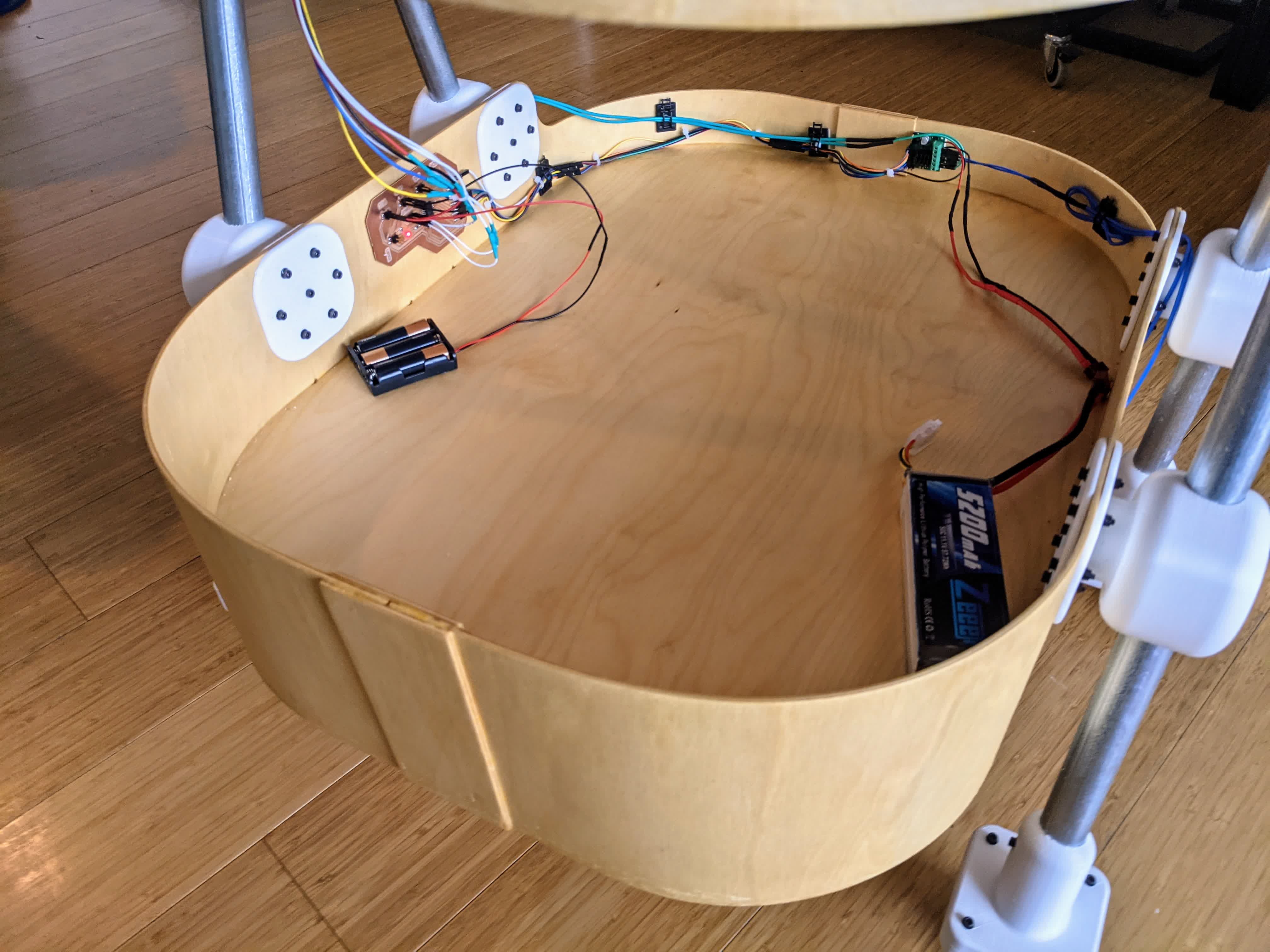
going from right to left, you can see the LiPo battery is unmounted so I can take it out and charge it. I will probably mount it using velcro against the right wall. I used double-sided tape to mount the h-bridge in the center against the wall. I did the same to mount my board to the left wall. The AA batteries are also unmounted, but I will use velcro on it as well. You can also see I used these cheap cable management clips to tie the cables together and mount them against the walls.
The sensors are mounted to the top bassinet using double-sided tape:
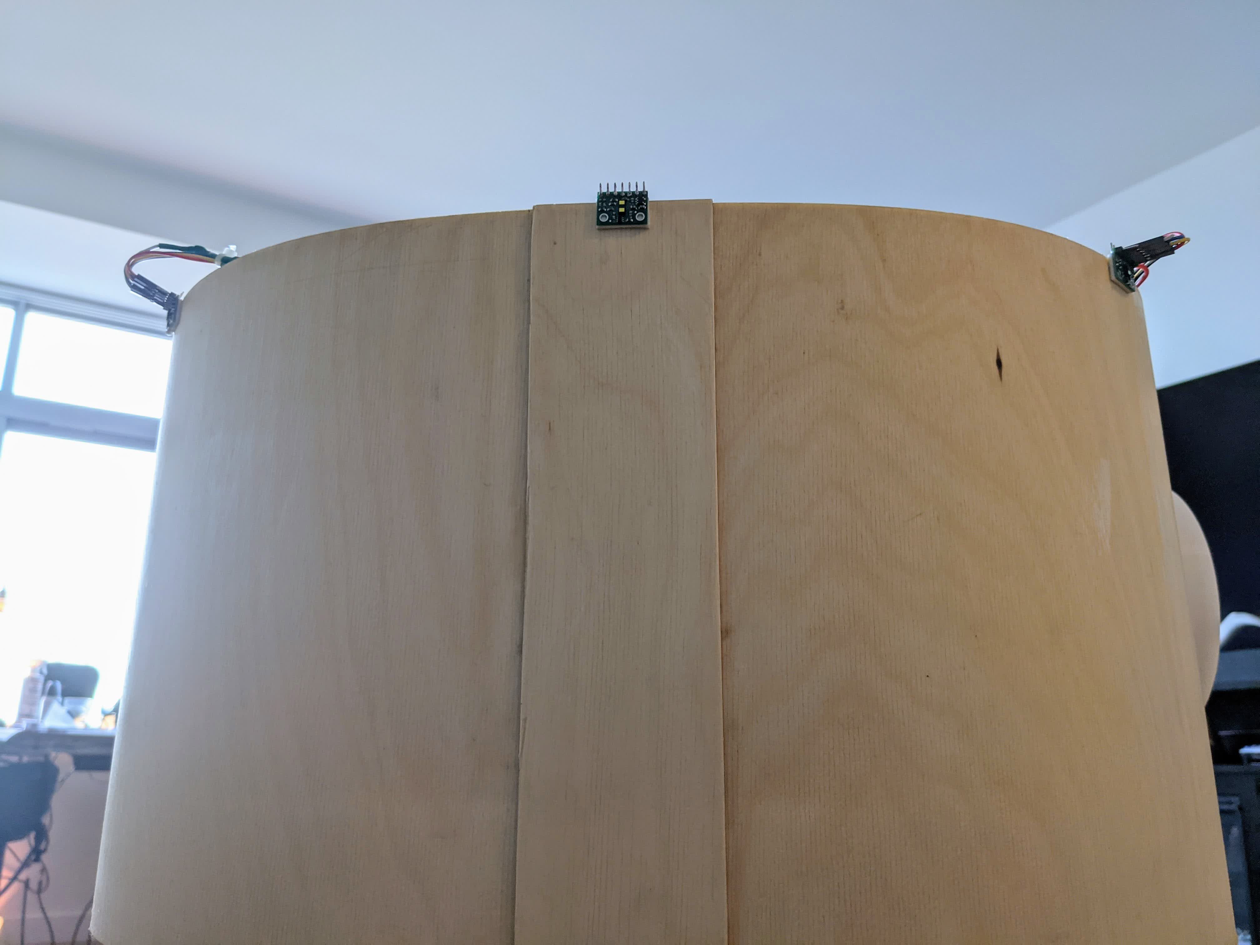
and their wires are tied together and routed down the side:
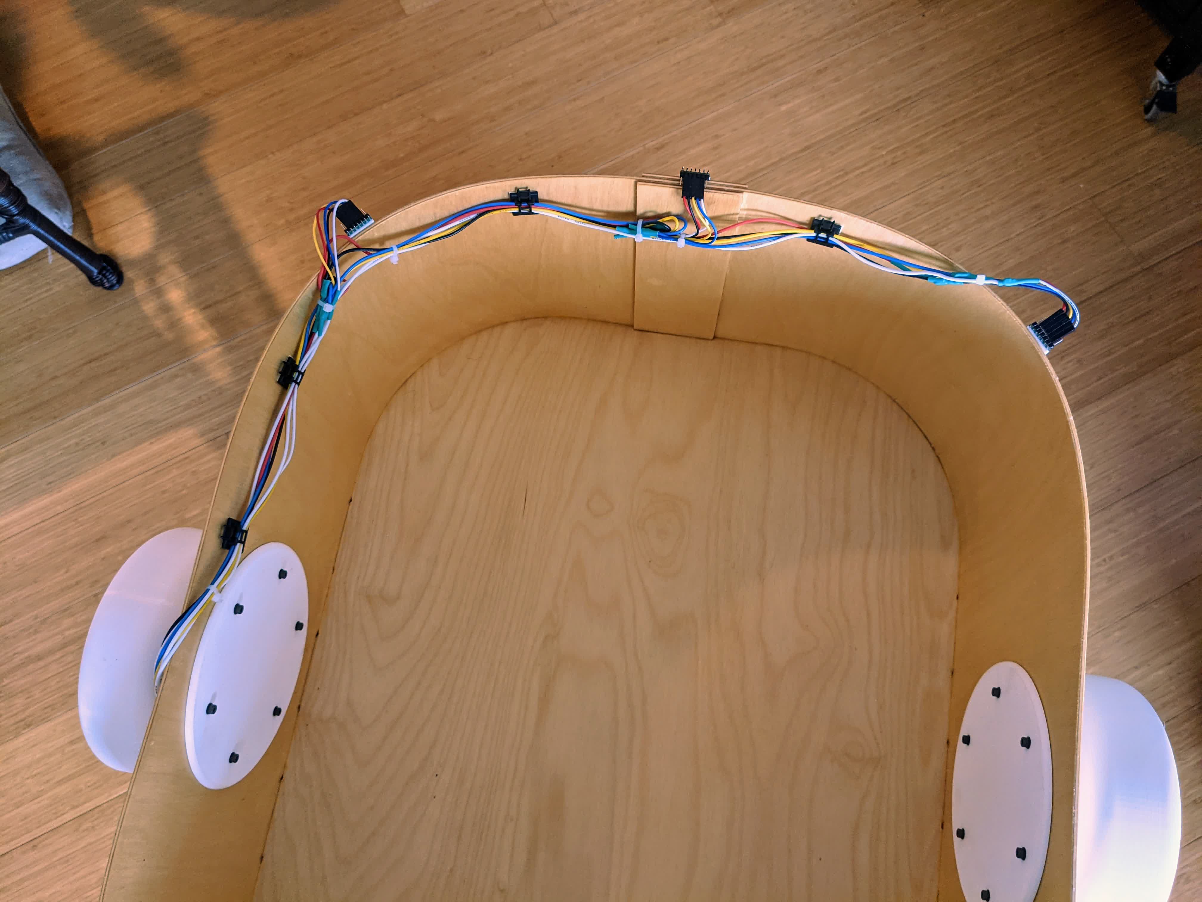
Here is the final result after all this clean up:
Final Result
I introduce you, to what my amazing wife, Lubna, who has been the most patient best partner a guy could hope for, especially throughout this hectic semester, has dubbed, Strobot, the stroller robot. Here is my initial demo video making sure things work:Finally is my project showcase:
and a Youtube link to share, like, subscribe, etc:
It has been one hell of a journey!!
Future Work & Improvements
This stroller changed from a follow me stroller to a hands-free stroller. It relies on the user to drive the stroller. Here are a few things that I would have done given some more time:-I wanted to implement PID control for smoother responsiveness, but opted for threshold control. I'm still wondering if PID would be better. The stroller will be in a constant state of jerking forward and backward, which is great for maintaining a specific distance, but could be disorienting for the baby. It really depends on how I tune the PID parameters though. It would have been nice to test though.
-It would be nice to implement the use of potentiometers with dials to control speed and acceleration.
-Having a kill switch is probably important as well.
-I wanted Stage 3 to have a camera to do object detection and object recognition to follow a single person, me. It could be calibrated to know the distance away from me based on my (or an object like a circle on my shirt) size on the camera sensor. I also would have liked to implement simple control functions, like steering in a way to keep me in the middle of the frame, or maybe lift an arm to steer it in that direction.
-The stroller can't really be used as a baby stroller because it is definitely not child safe. It could possibly require suspensions for a smoother ride. It also needs to be programmed better to accelerate and decelerate more smoothly so the baby is not flopping around. It could also use a cushion for the baby, and a better electronics housing.
There are other applications for this, like a personal items cart or a cart you can take to the grocery store, allowing you to carry stuff and keep your hands free. I'll see what I can do moving forward. This class has given me a ton of tools that I can't wait to use.