Web Design, Version Control, and Final Project Brainstorm
Laser & Vinyl Cutting
3D Scanning and Printing
Make Something Big
Molding and Casting
Electronics Production
Electronics Design
Embedded Programming
Input Devices
Output Devices
Networking & Communications
Interface and Application Programming
Final Project
Group Assignment
The group assignment was to probe an input device's analog levels and digital signals. This was done in collaboration with with Jordan, Maya, and Emma. The process and results can be viewed here.Input Devices
Assignment: Measure something. Add a sensor to a microcontroller board that you have designed and read it.
Adding Parts in Eagle
Since I wanted to make a remote that transmits light, I got a battery (CR2450) and its corresponding holder.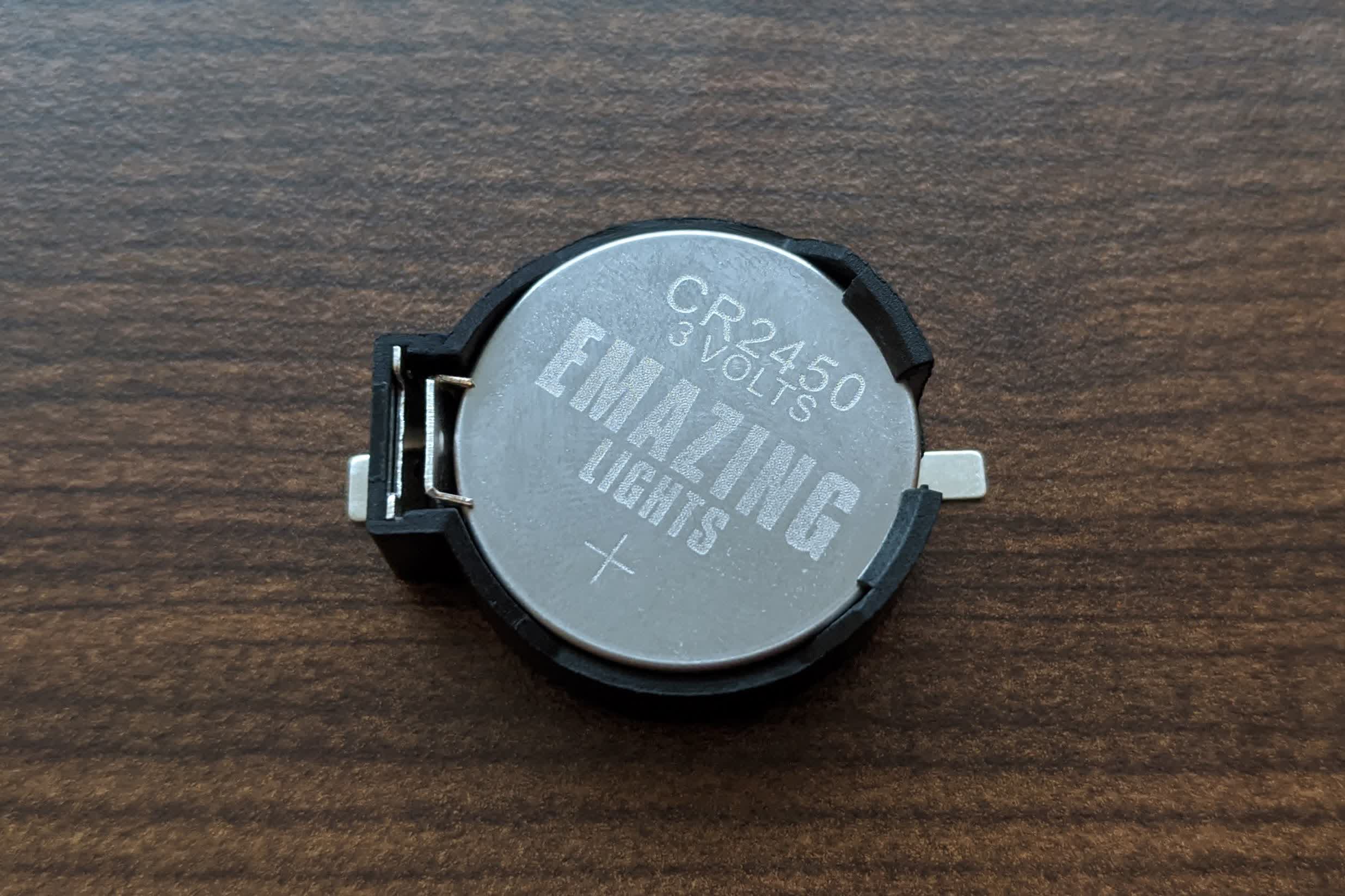
However, I couldn't find the part in any library, so I started by measured it myself.
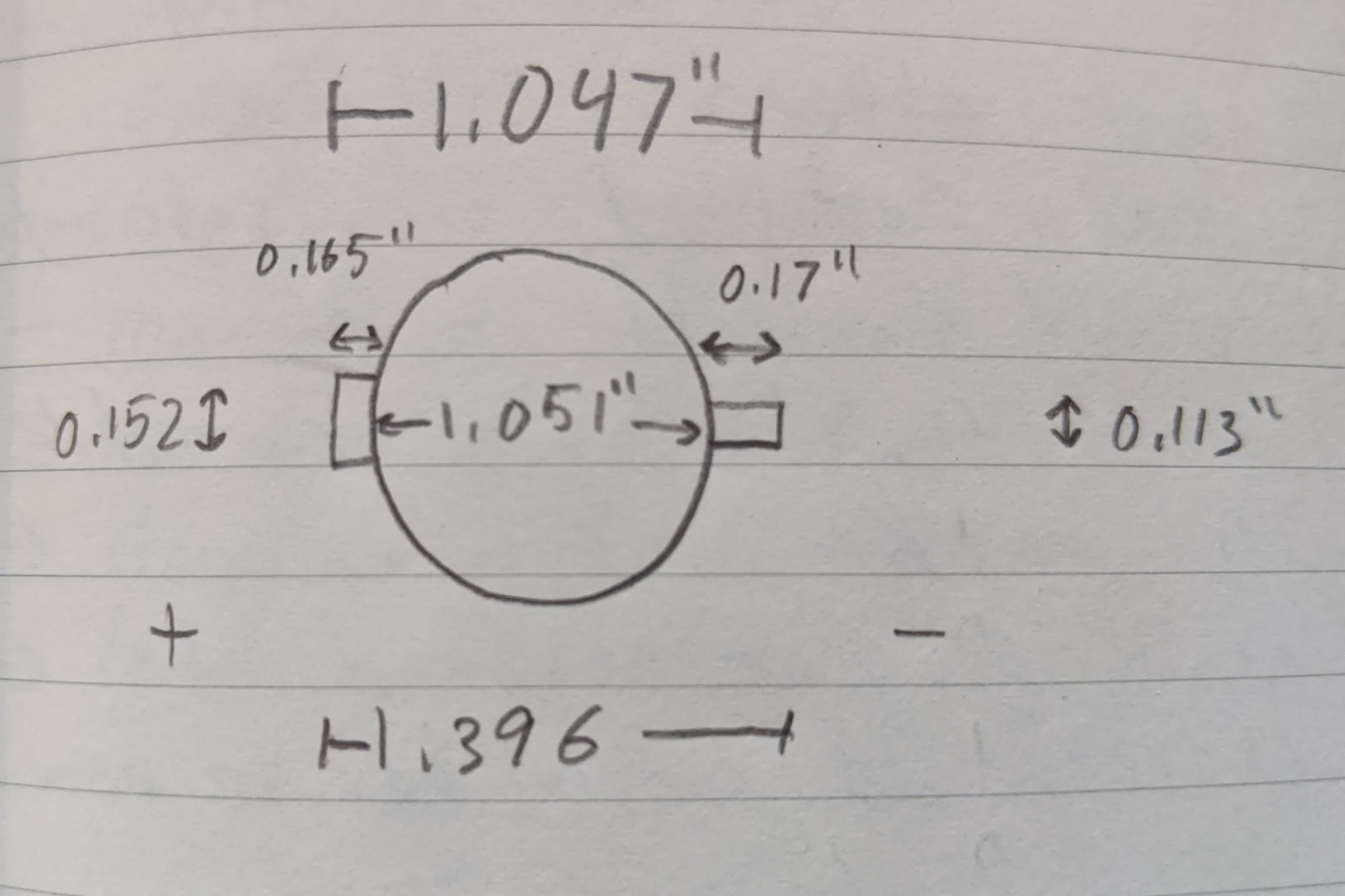
I then followed the following tutorials to add my part to Eagle:
-Library Basics Part 1: Creating your First Package in Autodesk Eagle
-Library Basics Part 2: Creating your First Symbol in Autodesk Eagle
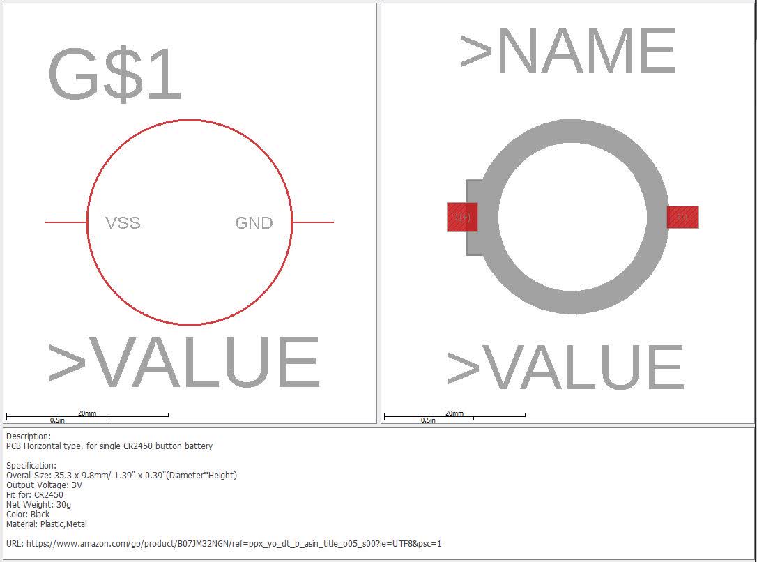
-Library Basics Part 3: Creating your First Device in Autodesk Eagle
Here is my battery holder in Eagle:
Clank Issues
fast clank due to change in mods:slowed it down, bit looks stable:
Results:
no traces.
Ran same gcode as last week and put board to compare:
Also tried spoofing a larger bit diameter in mods and cutting shallower, still no traces.
checking y belts:
So I went to the shop and got help from Anthony. We discovered 2 things:
-my belts were apparently too loose. So we tighened them up and put some Loctite on the pully set screws.
-my spindle was running in the oposite direction, so now it is spinning in the right orientation.
Photodetector Board
I decided to make a board with 3 input devices:-a visible light phototransistor
-an IR phototransistor
-an IR proximity sensor (here)
I wanted to test their sensitivity to see if I can make a sensing system for my final project.
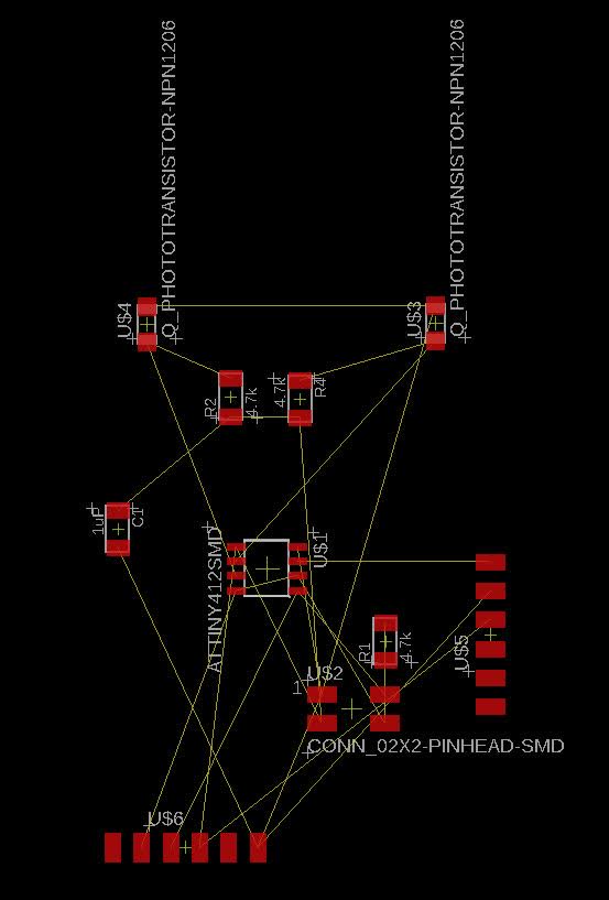
Here is the initial mess of components that frustrated me.
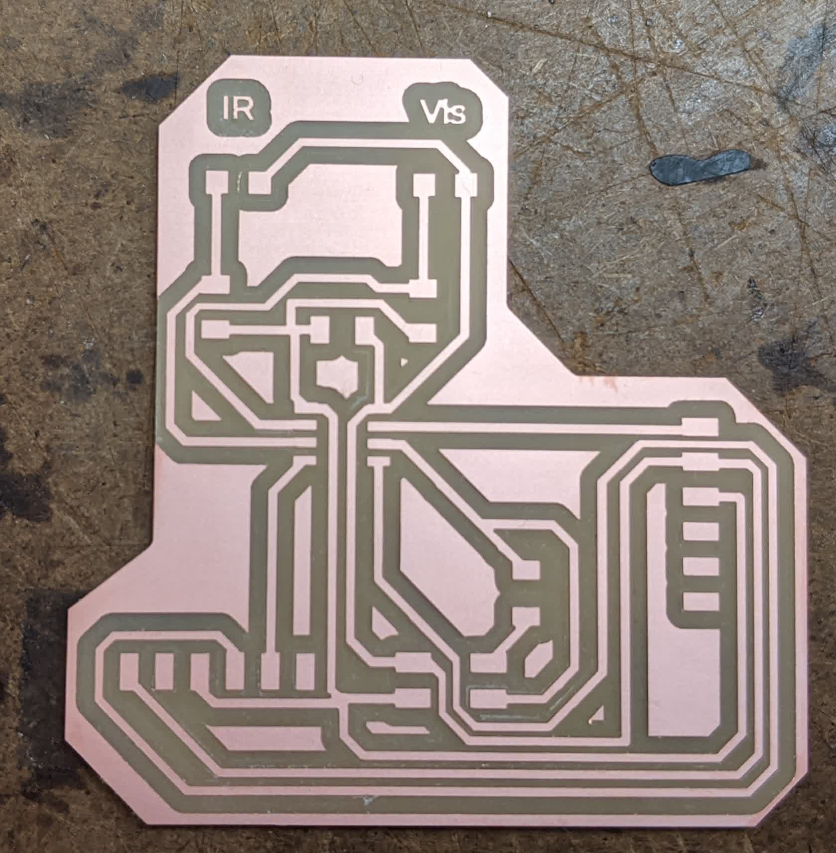
I eventually got a neat layout shown here:
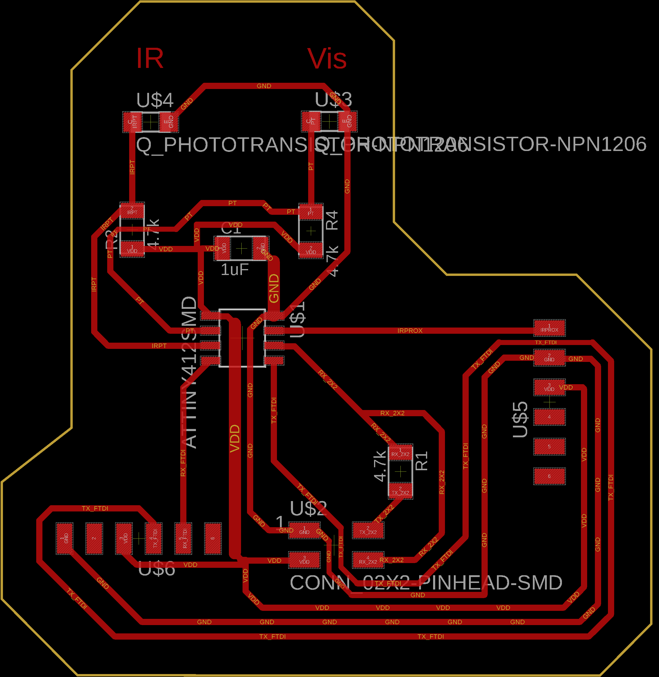
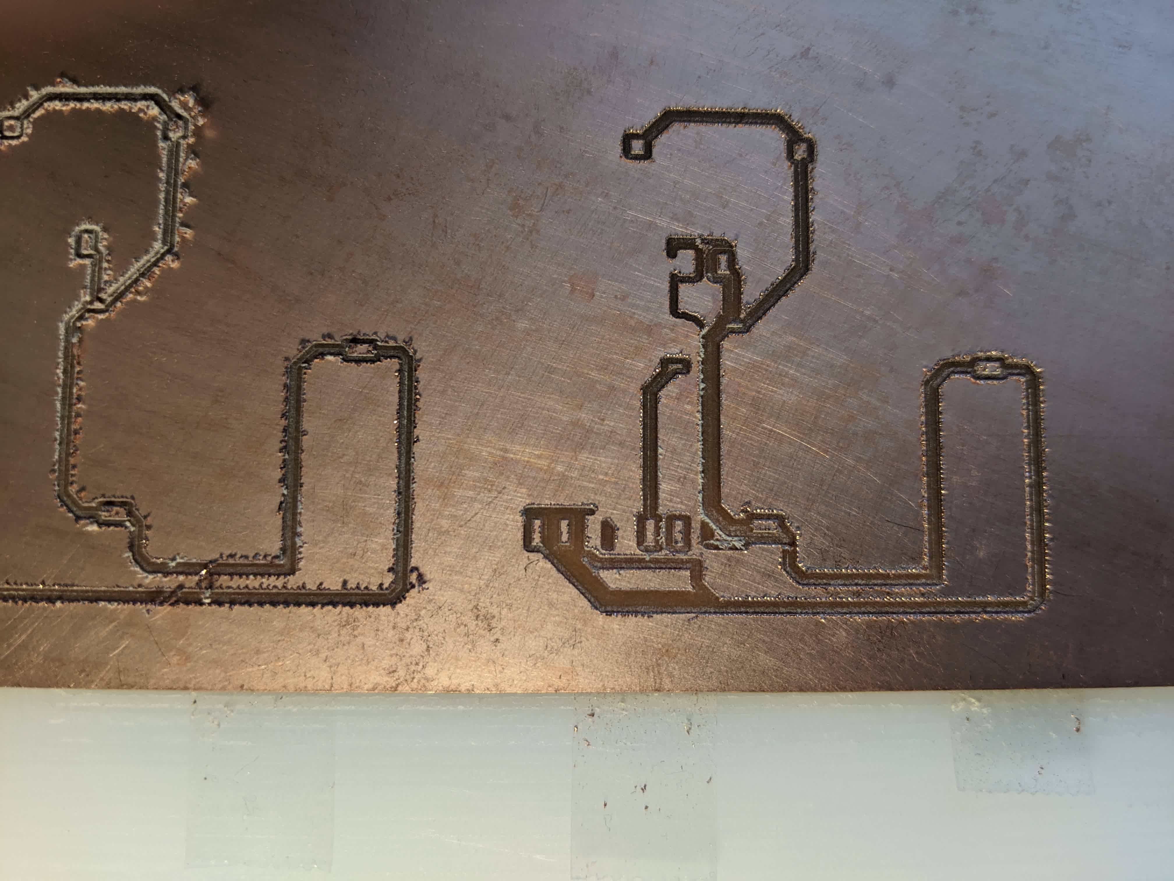
The traces are here:
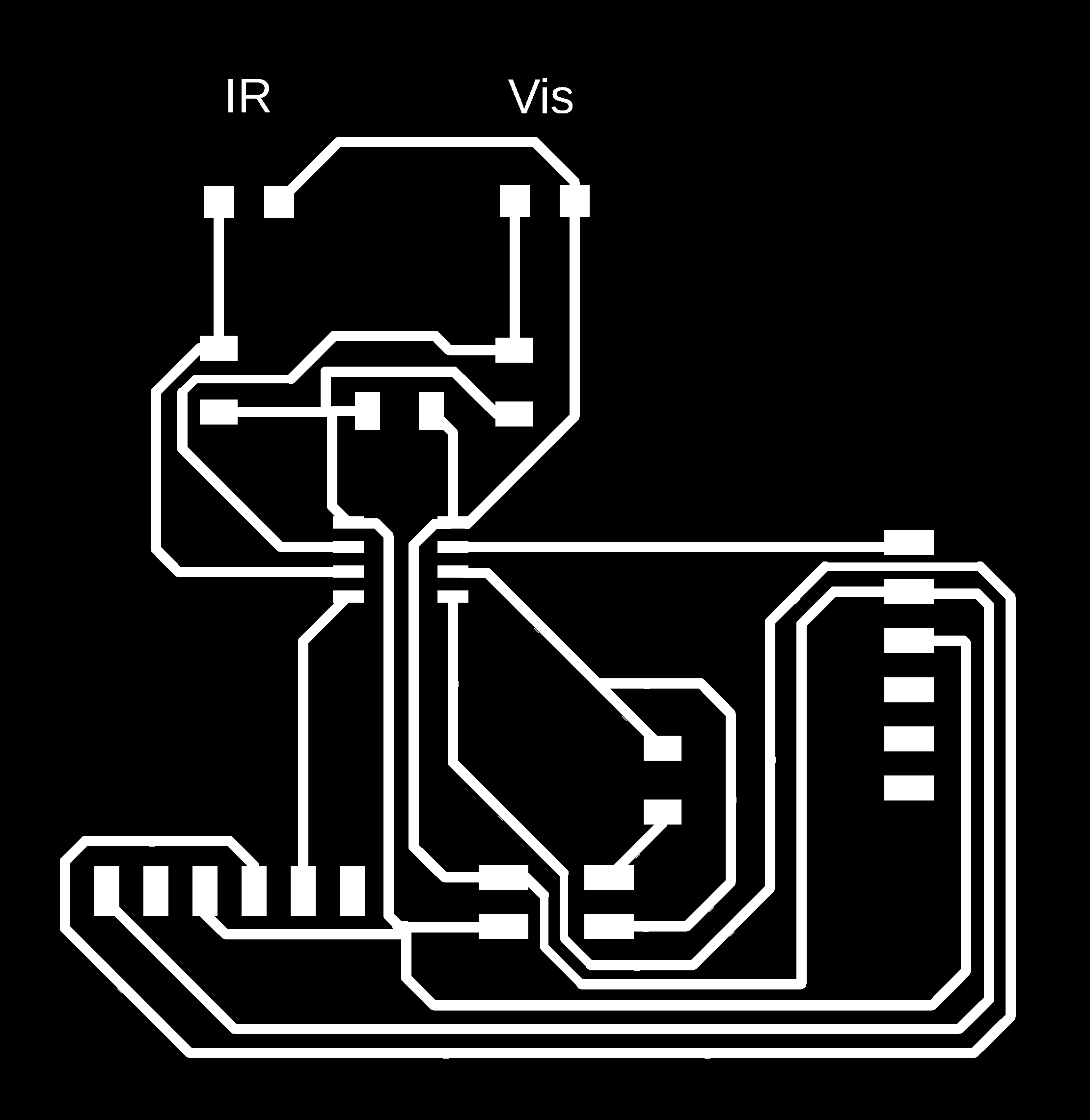
and this is the cutout:

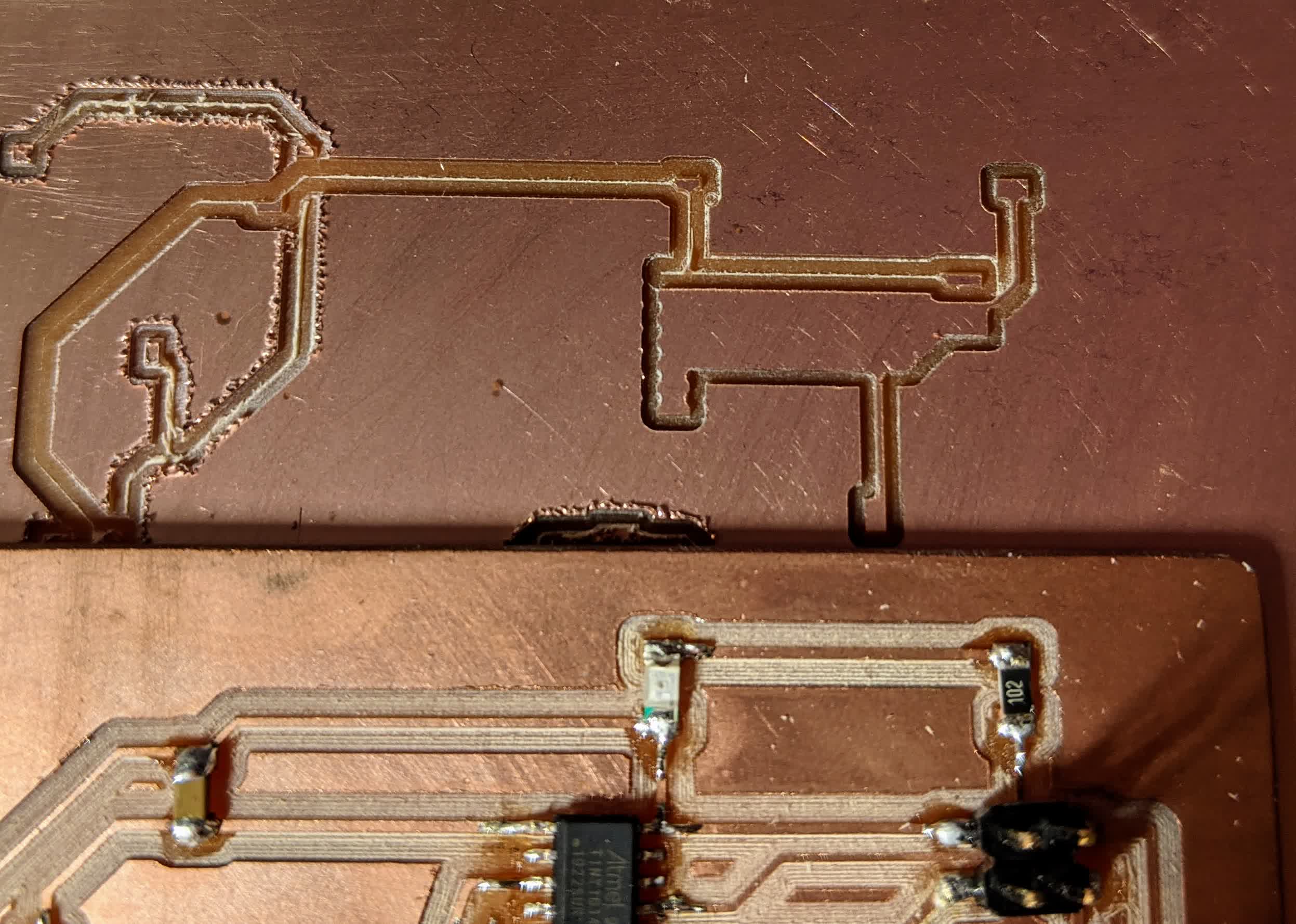
Due to my troubles with Clank, I went to shop and cut the board there:
The result kind of took my breath away. I could never mill anything out so clean on my Clank before, but hopefully that changes in the future.
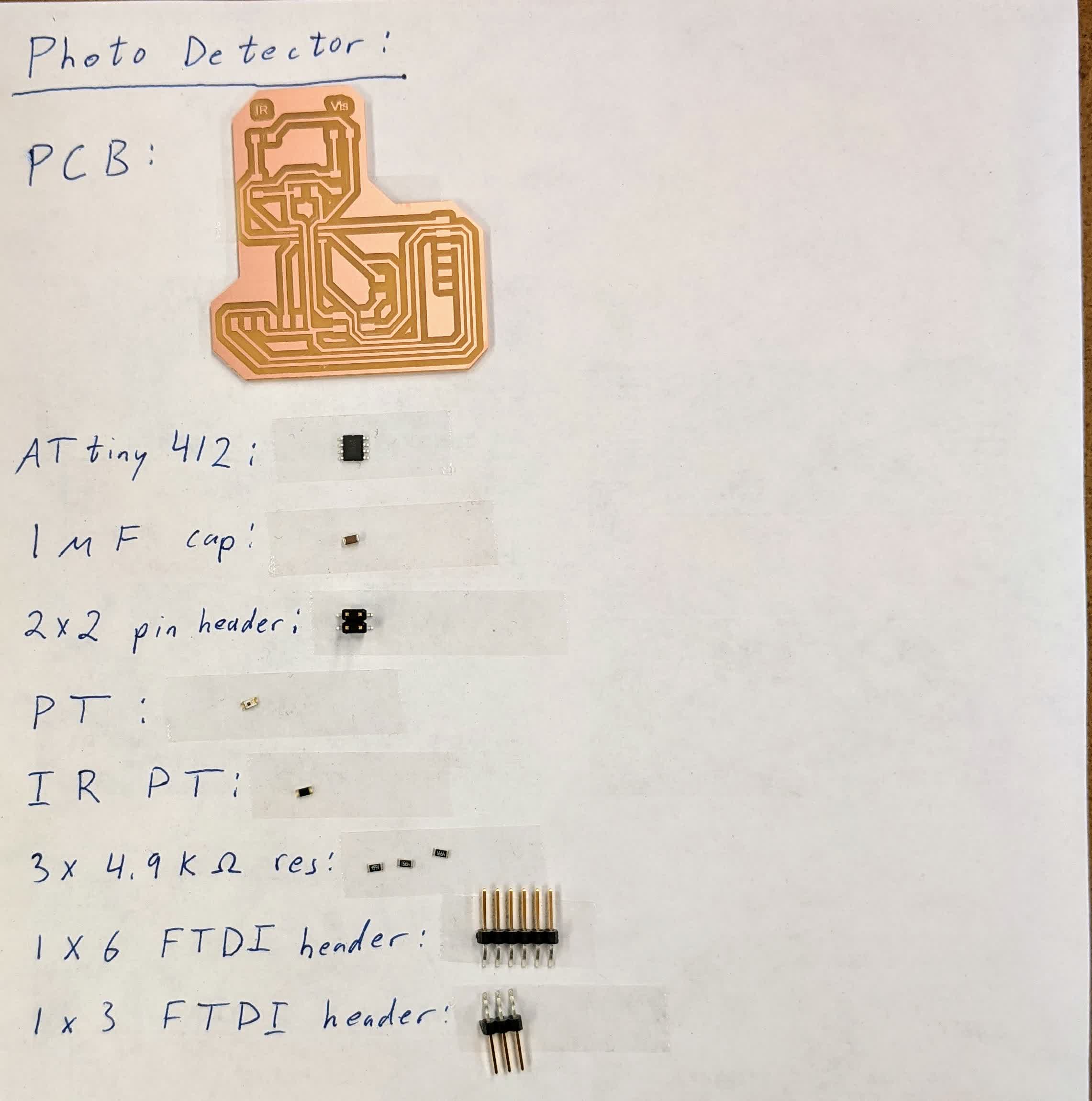
Here are all the components that went into this board.
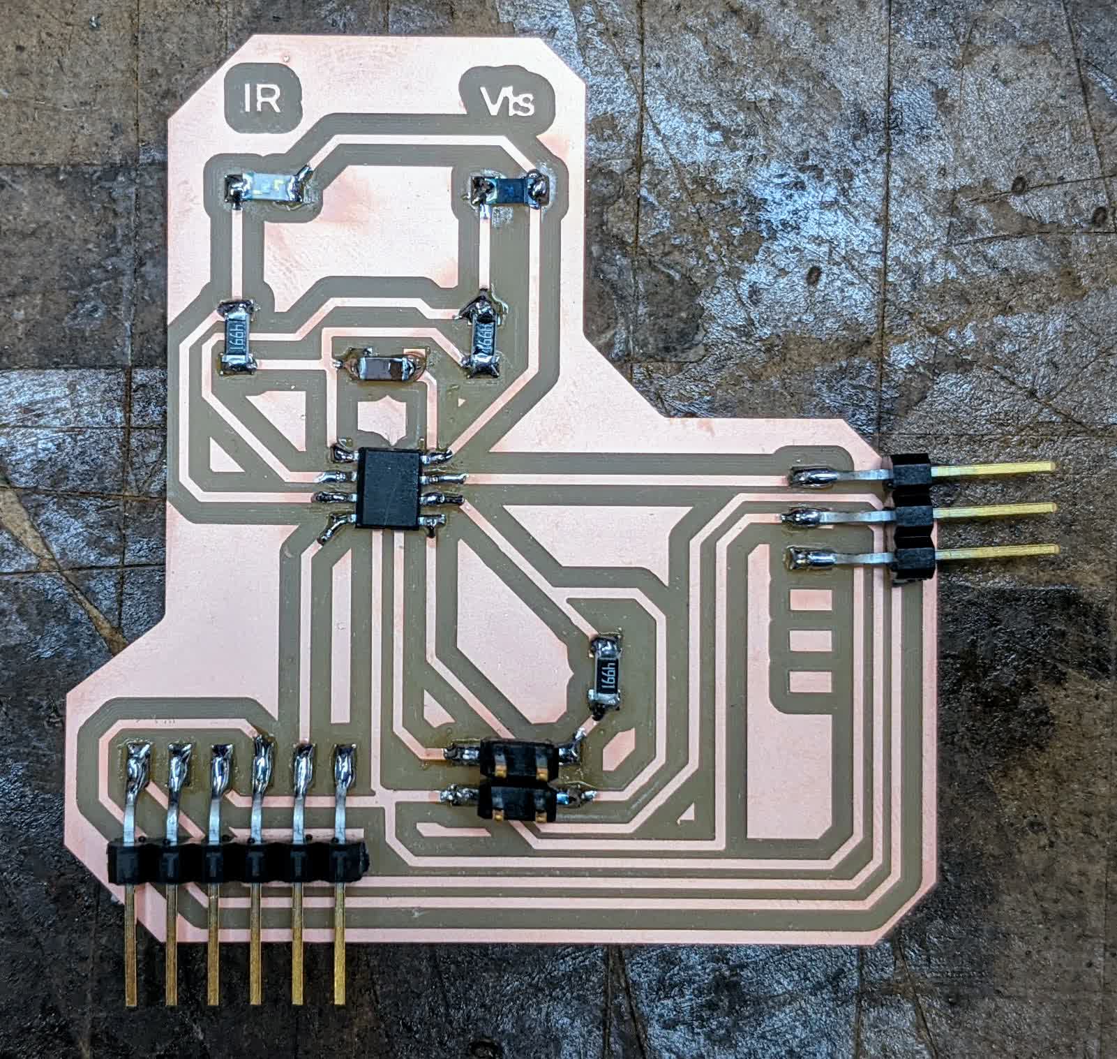
Here it is all done and soldered.
I programmed my board to
analogRead each of the 3 sensors:
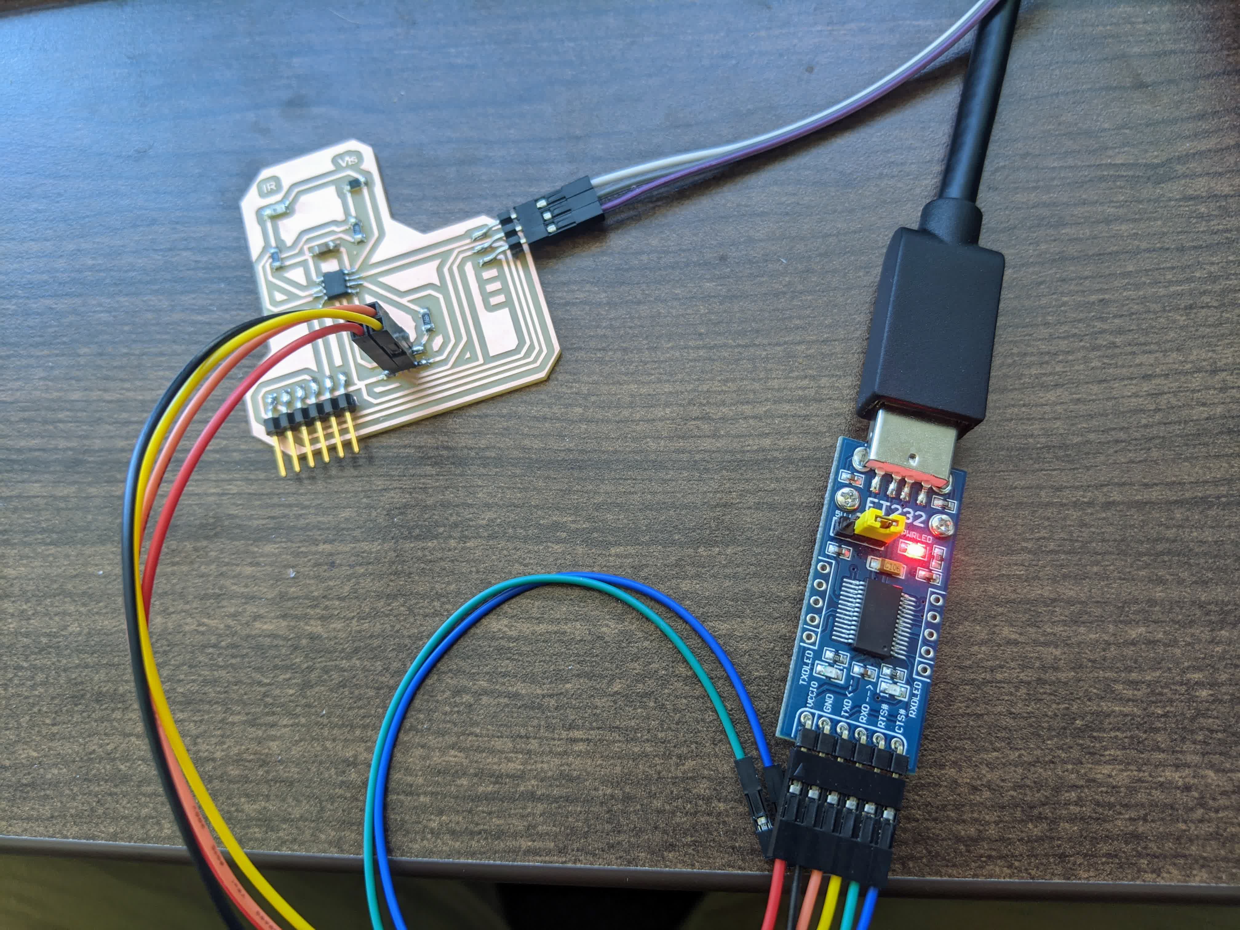
I downloaded and used putty to log the data. I still don't know how to see the data in real time. Here are the results:
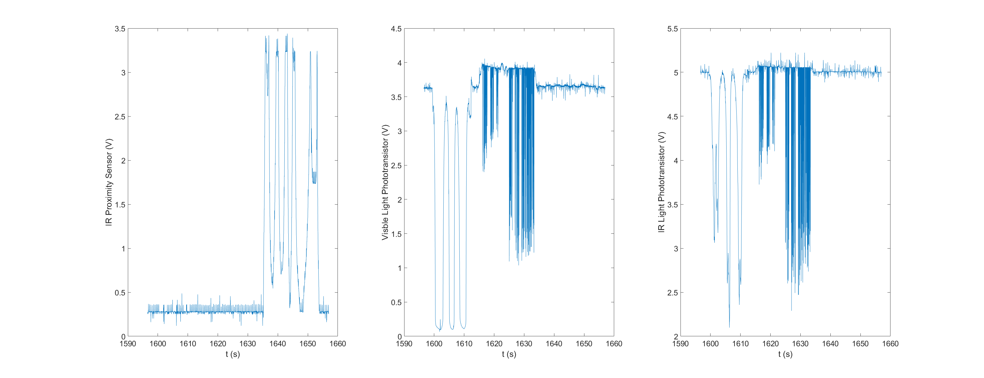
This was just one run to see it working. I used a flash light to test the visible light phototransistor, a tv remote to test the IR phototransistor, and my hand to test the IR proximity sensor.
The flashlight was used first(t=1600-1620) shining on and off, and you can see the big drops in the center plot, and you can aslo see that my flash light evidently emits IR shown on the right plot.
I then used my TV remote, pointing at at the board and pushing buttons. When the buttons are pushed, the IR is emitted in a modulated high-frequency way to power on and a different modulates signal to indicate other functions like volume up. You can see how noisy the data looks from t=1620-1640 showing the modulated nature of the buttons being pushed. I thought it was interesting that the visible light phototransistor also picked up on the TV remote IR light.
Finally, I used my hand and brought it closer and farther to the IR proximity sensor a few times from t=1640-end, and you can see it reports voltage values higher than ~0.3 V when an object is detected. I was disapointed to see that the range is pretty low...~80cm.
All in all, I think I'm going to need to look for a different detection method from any of these sesnors. They all have a very small range, smaller than what I'd like. The phototransistors might work if I used a lot of LED's or a bight flashlight pointed directly at the sensor. The IR proximity would work if I didn't mind being so close to the stroller as I am walking.
An alternative use of the IR proximity sensor would be to use it to detect objects that appear closer than 80cm and make the stroller break. I'll have to think about whether I want to use these or not, none the less, this was a great exercise. Code:
        /*

  Analog Light and Distance Sensing

  This code is written to read the values of:

  -phototransistor: connected to pin 3 (Analog pin 1)

  -IR phototransistor: connected to pin 2 (Analog pin 0)

  -IR proximity sensor: connected to pin 7 (Analog pin 4)

  The board being used is the ATtiny412 which has the following important pins:

  -VCC (pin 1)

  -GND (pin 8)

  -PA6 (pin 2) is default TXD - Arduino pin 0

  -PA7 (pin 3) is default RXD - Arduino pin 1

  -PA1 (pin 4) is alternate TXD - Arduino pin 2

  -PA2 (pin 5) is alternate RXD - Arduino pin 3

  -PA0 (pin 6) is UPDI - Arduino pin 5

  -PA3 (pin 7) - Arduino pin 4

*/

//Define pins

int prox=4; int IRPT=0; int VisPT=1;int RxFTDI=2;int TxFTDI=3;int UPDI=5;


//Define variables and initialize

int Dist=0; int Vis=0; int IR=0;int delayTime=1;


// the setup routine runs once when you press reset:

void setup() {

  // initialize serial communication at 9600 bits per second:

  Serial.swap(1); //set the mapping to the alternate (1) or default (0) UART pins

  Serial.begin(9600);

  pinMode(prox,INPUT);pinMode(IRPT,INPUT);pinMode(VisPT,INPUT);

}


// the loop routine runs over and over again forever:

void loop() {

  // read the input on analog pin 0:

  Dist = analogRead(prox);

  delay(delayTime);        // delay in between reads for stability

  Vis=analogRead(VisPT);

  delay(delayTime);        // delay in between reads for stability

  IR=analogRead(IRPT);

  delay(delayTime);        // delay in between reads for stability

  // print out the value you read:

  Serial.print(millis());

  //Serial.print(",");

  Serial.println(Dist);

  //Serial.print(",");

  Serial.println(Vis);

  //Serial.print(",");

  Serial.println(IR);


}
Matlab script to read and plot log data:
  clear all; close all;

%% Import data from text file

% Script for importing data from the following text file:

%    filename: C:\Users\Omar\Desktop\ClassRepo\archsite\people\OmarAlDajani\Week8\logFiles\putty.log


% Setup the Import Options and import the data

opts = delimitedTextImportOptions("NumVariables", 2);


% Specify range and delimiter

opts.DataLines = [3, Inf];

opts.Delimiter = ",";


% Specify column names and types

opts.VariableNames = ["PuTTYlog20201104093000", "VarName2"];

opts.VariableTypes = ["double", "double"];


% Specify file level properties

opts.ExtraColumnsRule = "ignore";

opts.EmptyLineRule = "read";


% Import the data

putty = readtable("C:\Users\Omar\Desktop\ClassRepo\archsite\people\OmarAlDajani\Week8\logFiles\putty.log", opts);


% Convert to output type

putty = table2array(putty);


% Clear temporary variables

clear opts

%% Read Raw Values


t=putty(1:3:end,1);

Dist=putty(1:3:end,2);

Vis=putty(2:3:end,2);

IR=putty(3:3:end,2);


AllData=[t Dist Vis IR];


%% Read Raw Values

VCC=5.3;

bits=10;

t_s=t/10^3; %convert ms to s

Dist_V=Dist*VCC/(2^bits-1); %convert bits to volts

Vis_V=Vis*VCC/(2^bits-1); %convert bits to volts

IR_V=IR*VCC/(2^bits-1); %convert bits to volts

AllData_V=[t_s Dist_V Vis_V IR_V];

%% plot

figure(1)

subplot(1,3,1)

plot(t_s,Dist_V)

xlabel('t (s)');ylabel('IR Proximity Sensor (V)');set(gca,'fontsize',20);

subplot(1,3,2)

plot(t_s,Vis_V)

xlabel('t (s)');ylabel('Visble Light Phototransistor (V)');set(gca,'fontsize',20);

subplot(1,3,3)

plot(t_s,IR_V)

xlabel('t (s)');ylabel('IR Light Phototransistor (V)');set(gca,'fontsize',20)

%%

save('Log3_flash_TV_hand.mat','t','Dist','Vis','IR')