Web Design, Version Control, and Final Project Brainstorm
Laser & Vinyl Cutting
3D Scanning and Printing
Make Something Big
Molding and Casting
Electronics Production
Electronics Design
Embedded Programming
Input Devices
Output Devices
Networking & Communications
Interface and Application Programming
Final Project
Group Assignment
The group assignment was to send a message between two projects. This was done in collaboration with with Jordan, Maya, and Emma. The process and results can be viewed here.Networking and Communications
Assignment: Design, build, and connect wired or wireless node(s) with netwrok or bus addresses.
I used this week's assignment to work on the electronic side of my final project. This includes making a board for a time of flight sensor, making a board for controlling 2 motors, and communicating between the two where the distance from the time of flight board is used as a control parameter on the motor board.
ATtiny3216 Breakout Board
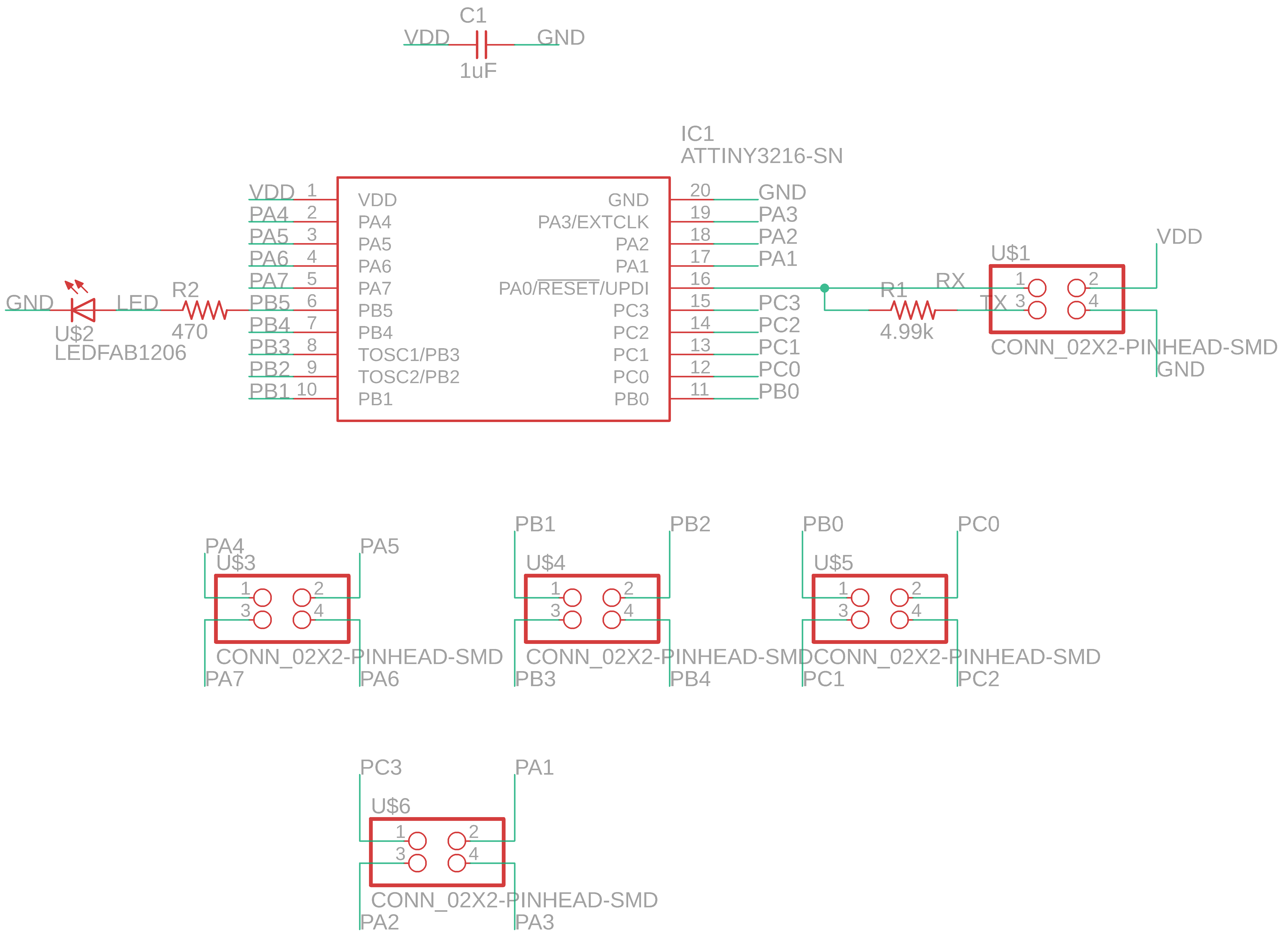
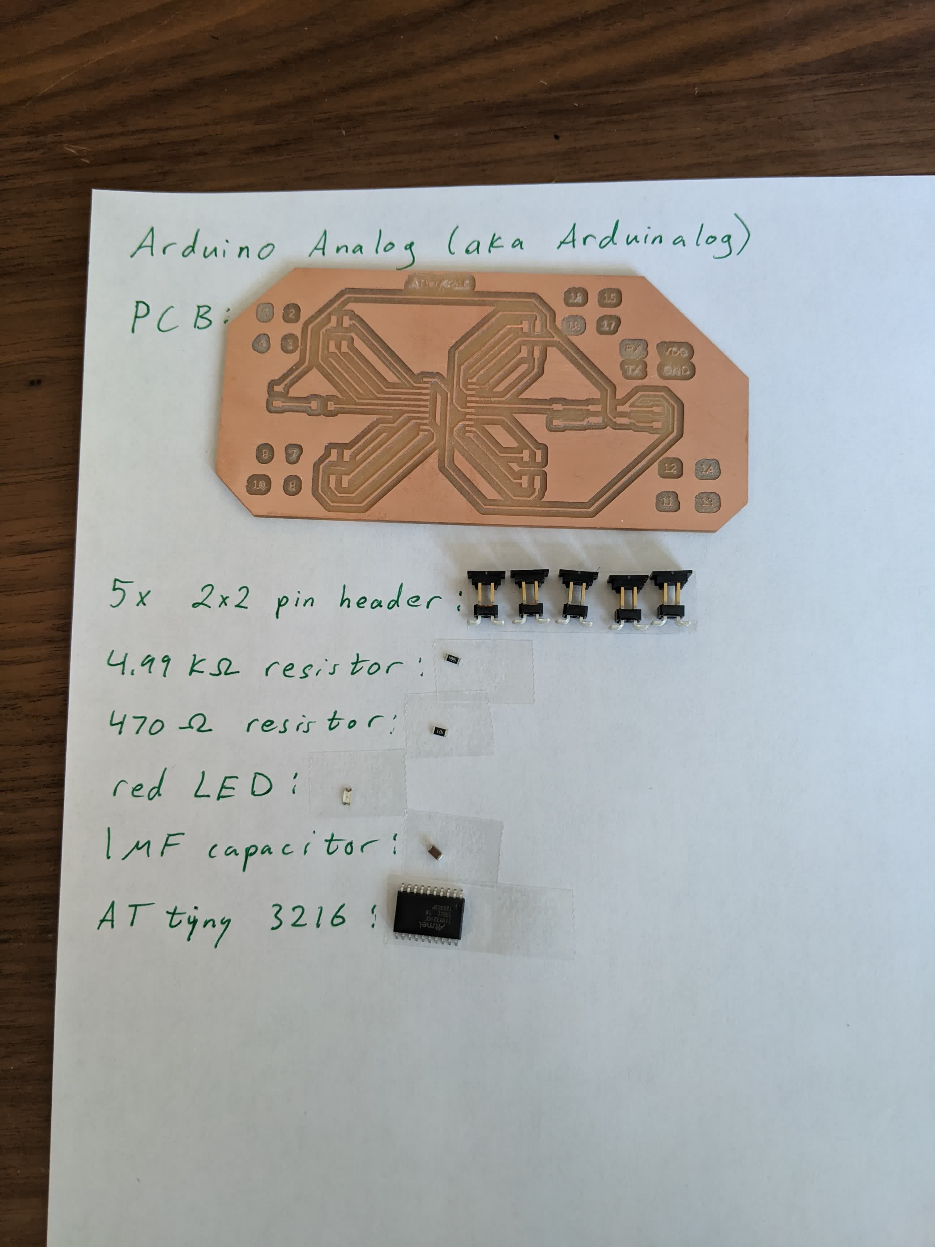
Given my unfortuante experience in the previous weeks, where I had to remake entire boards multiple times due to small things, like running out of memory on a microprocessor or having traces connected to the wrong microprocessor pins or , I decided to make a breakout board using the ATtiny 3216. I designed it to be an analog to an Arduino, where it is just the microprocessor, a single LED, and UPDI pins, and then breakout pins to all other pins on the microprocessor.Here is the schematic of the board:
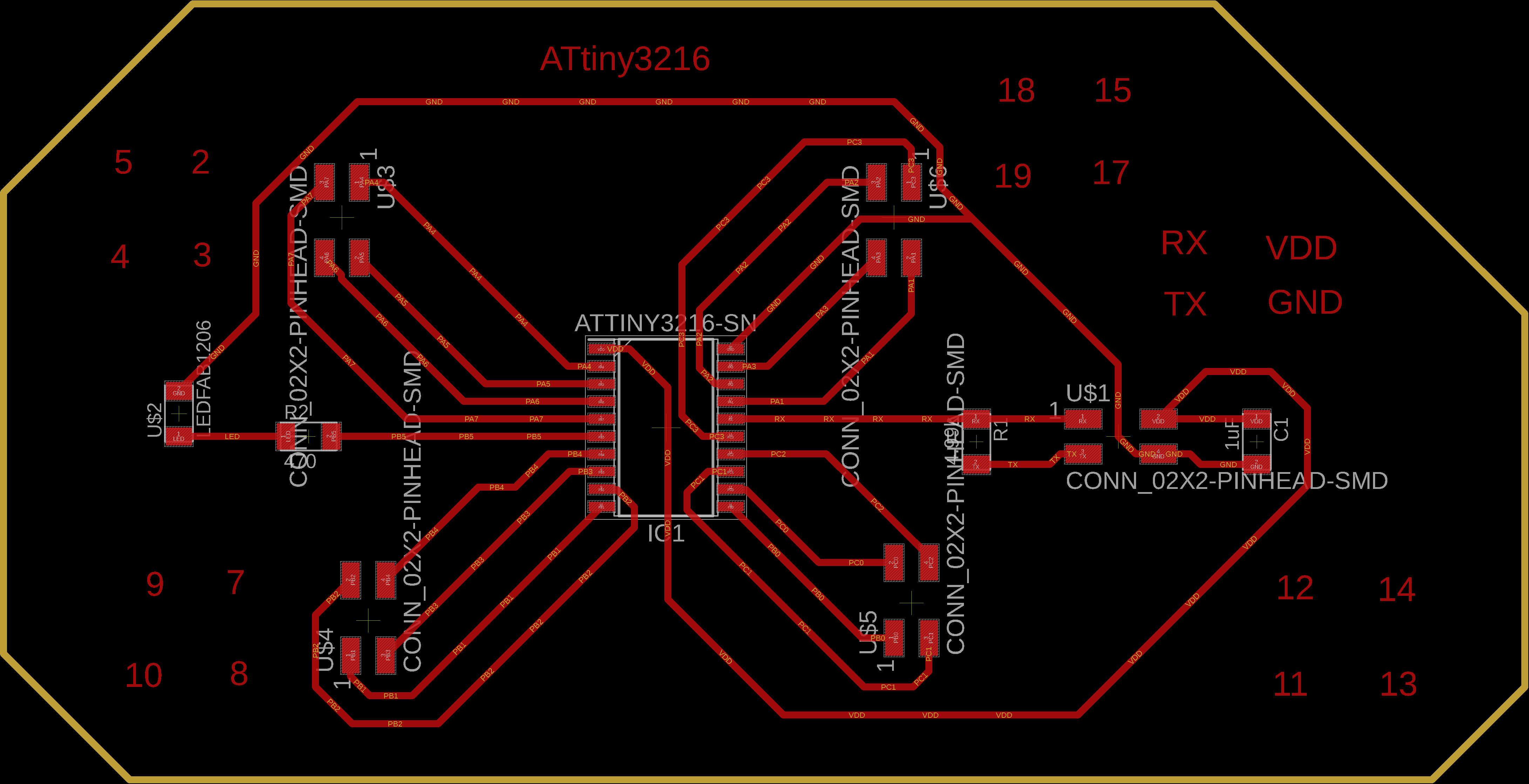
Here is the layout of the board:
I then used mods to generate traces using the 1/64" endmill with a cut depth and max depth of 0.004" and 6 offsets running at 2.5 in/s:
and the cutout was generated using the 1/32" endmill with a cut depth of 0.01" and maximum depth of 0.57" (measured the thickness of the board) with the same speed of 2.5 in/s:

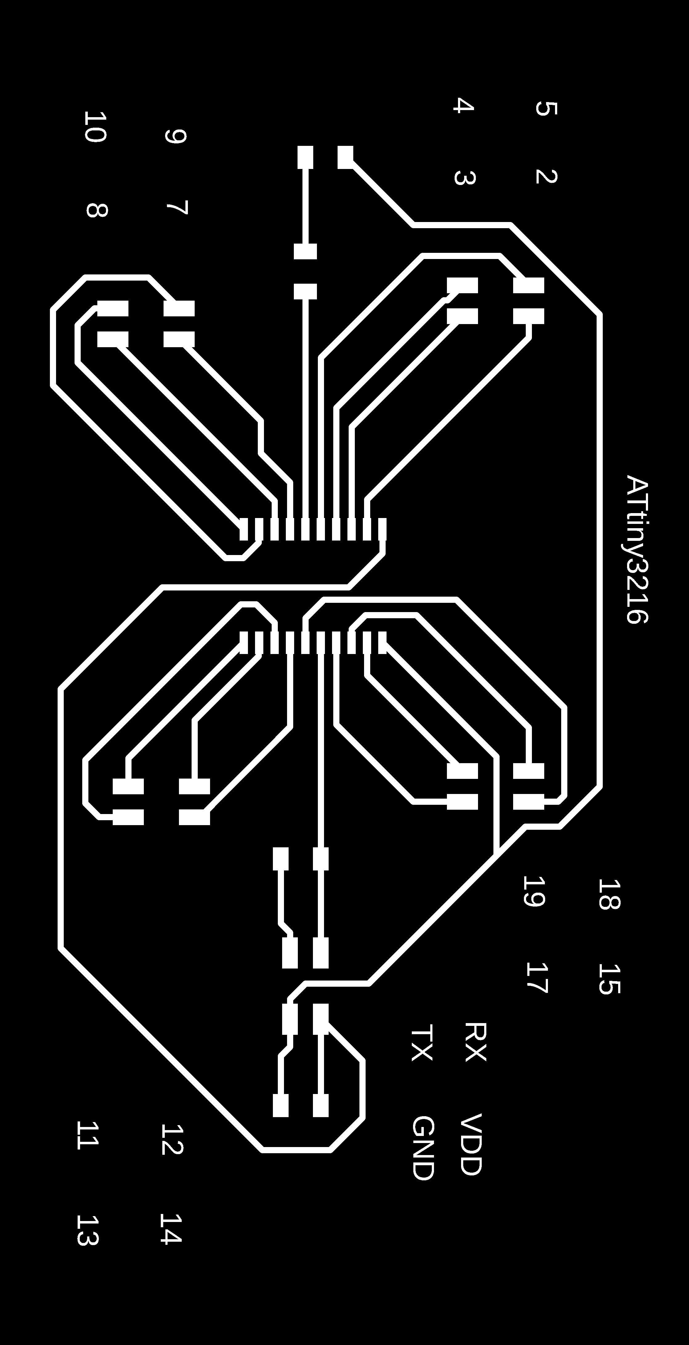
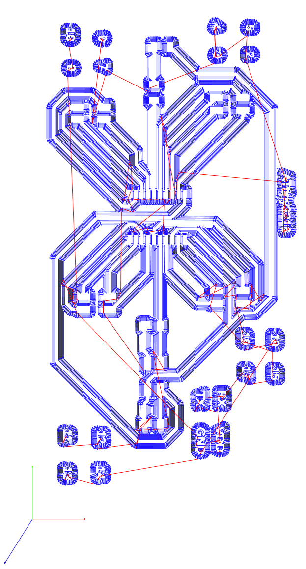
Here are the toolpaths:

The gcodes are at the bottom of the page.
Next I layed out all the components:
And here is the end result:
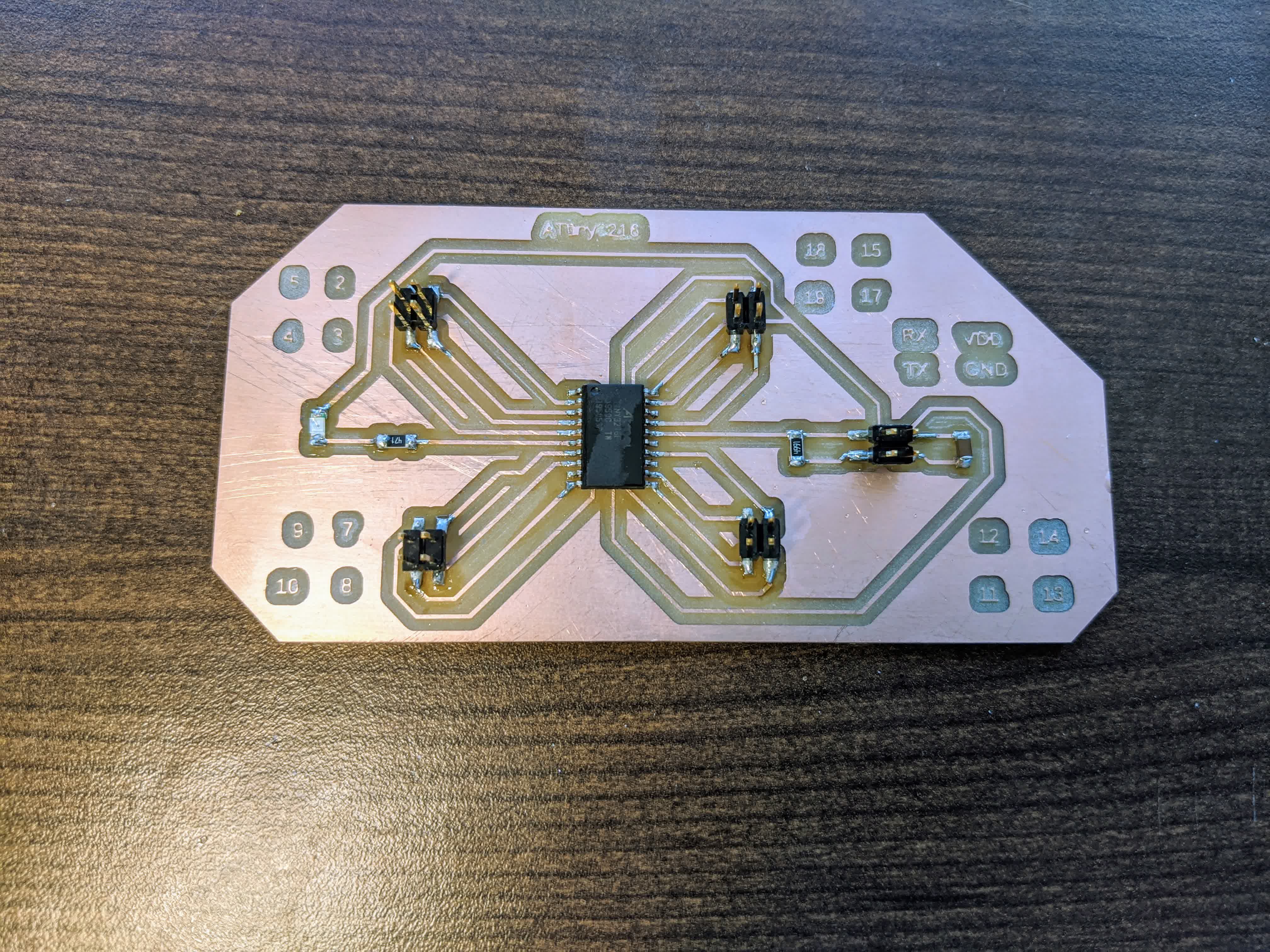
I plan to use this board to test run my motors and networking setup. A final motor control board once I am certain how many and which pins I need for my final project. You will see later, this has come in extremely handy for quickly fixing mistakes by simply plugging things in and out with jumper wires.
Setting up the Motor Control Board
The break out board is what I am using this week to test things. Before I go into the board, we have to first talk about the components. I'll start with the motors.Motors
Given the beefy weight of my project, I calculated that I would need a beefy motor. The exact specifics can be seen in the Final Project tab. To keep it simple, the motor I am working with is a 12V DC gearmotor which I picked up from Pololu here. I specifically got a 30:1 gear ratio which provides a no-load speed of 330 rpm and a stall torque of 14 kg-cm. The only thing I did to prep the motor was to solder wires onto the pins: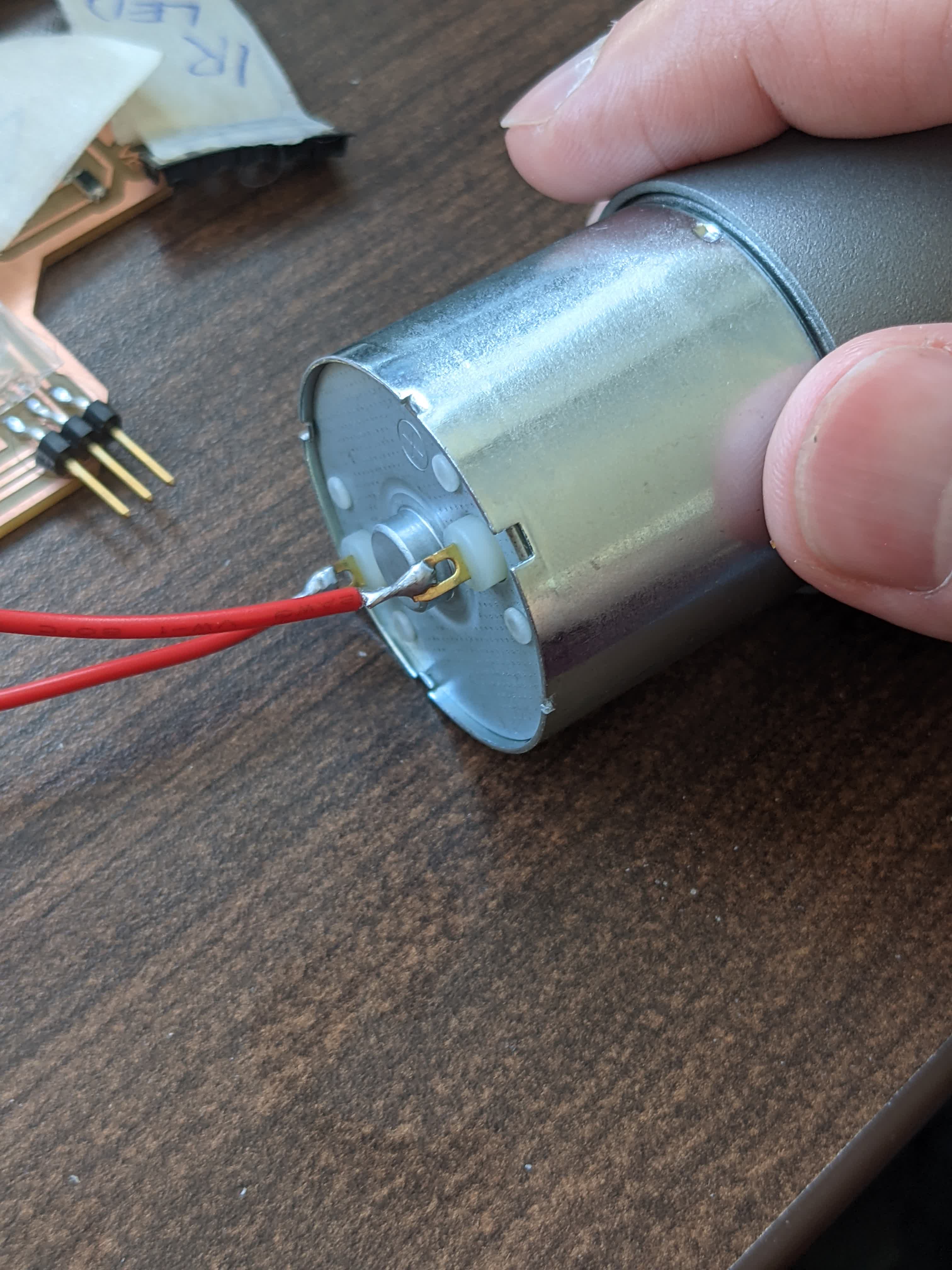
A tip I learned from the internet was to strip the wire, twist the strands, solder them straight, use pliers to bend, hook the bend into the pin hole on the motor, close the hook, then apply generous extra solder to ensure full contact and hold it in place.
The most important aspect of selecting these motors is that they have a stall current of 5.5 A. Here is the performance chart of this motor (pulled from teh data sheet):

The red curve and left axis show the current the motor draws as a function of torque. I estimated that my project will need as little as 20 kg-mm and as high as 60 kg-mm (particularly at start up), requiring a current draw in the 1-3 A range and possibly more (or less). This led me to find that the A4953 h-bridge which I used in Output Devices week might not be sufficient as it is rated for a maximum of 2A, which means it cannot continuously operate at 2 A. So I started to look for an h-bridge that can output 4-6 A.
H-Bridge
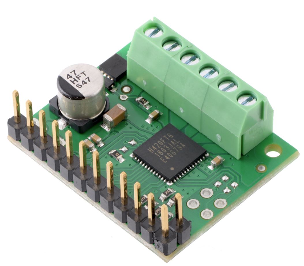
After much searching and consulting, I found an h-bridge that would meet my needs for the final project (hopefully).I found the TB67H420FTG Dual/Single Motor Driver Carrier on Pololu here. It is an h-bridge mounted on a carrier board. This h-bridge can control one or two motors simultaneously. It can take in 10-47V, and output 1.7A continuous current in dual-channel mode, and 4.5A peak. These current numbers are what I estimated that I will need. Given how heavy my project is, this h-bridge can give me a high enough current to get it moving, and then enough current to keep it moving. If I find that this is not enough, I can always use a second one in single channel mode to provide 3.4A continuous, and 9A peak. For now, I am using just the 1 though. I found that it operates exactly like the A4953, it just has enough pins for 2 motors and pins to control single or dual channel mode. Here's an image of this h-bridge pulled from the website:
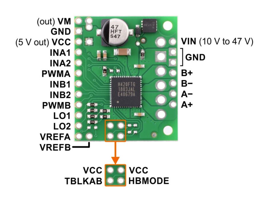
I actually went ahead and soldered on the pins and screw terminals like they show here:
With the motors and h-bridge setup, I was ready to connect everything to the break out board.
Connecting Motors and H-Bridge
Here is a schematic showing how I connected things to be programmable: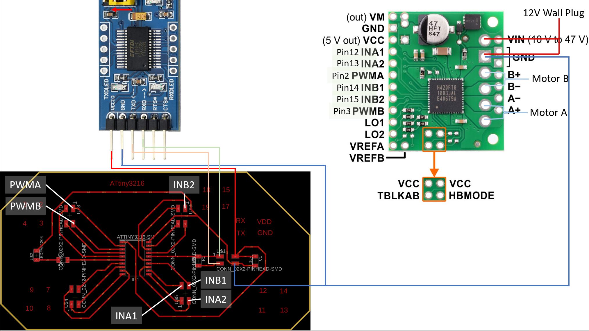
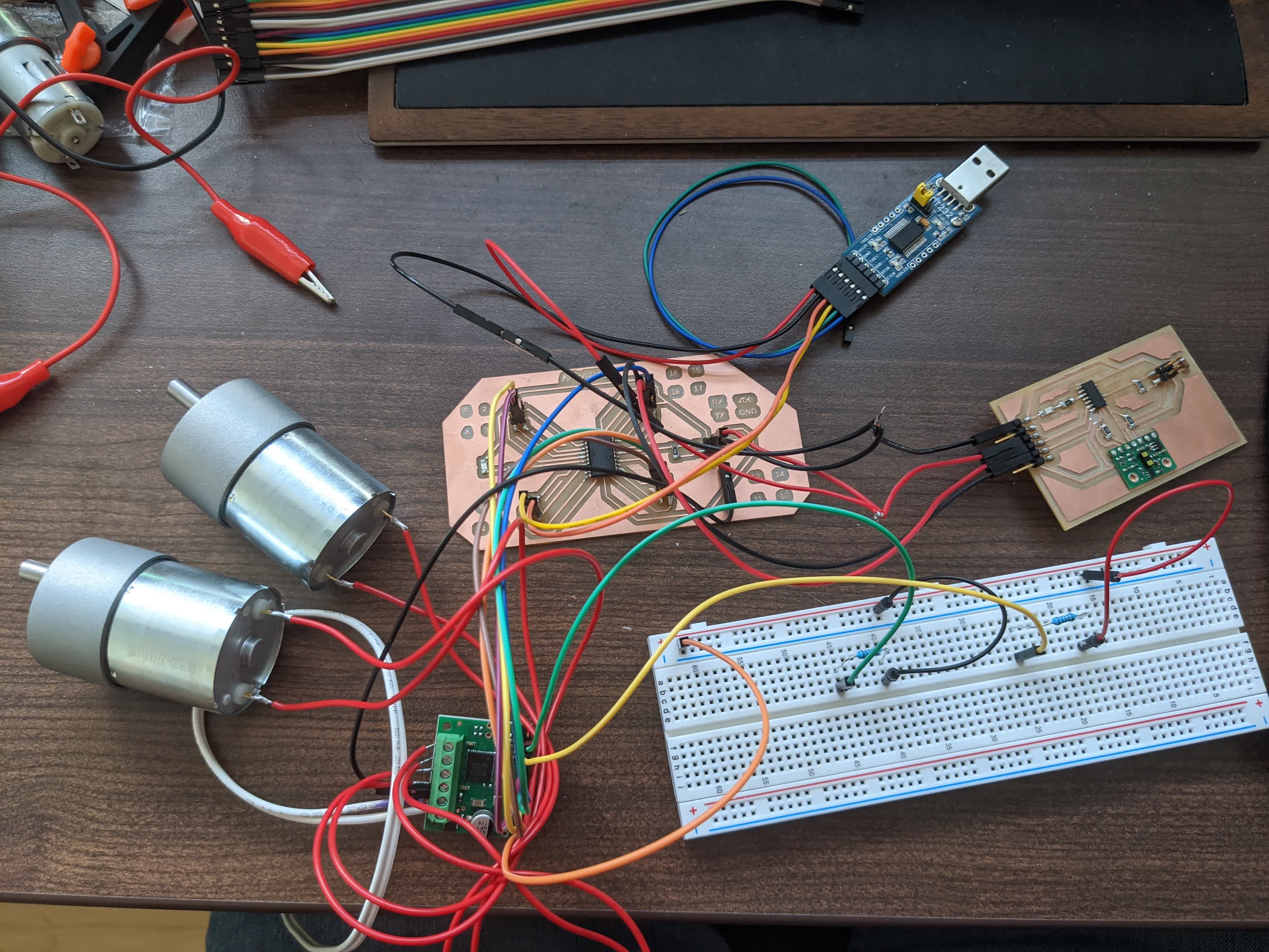
here is what it looks like in real life:
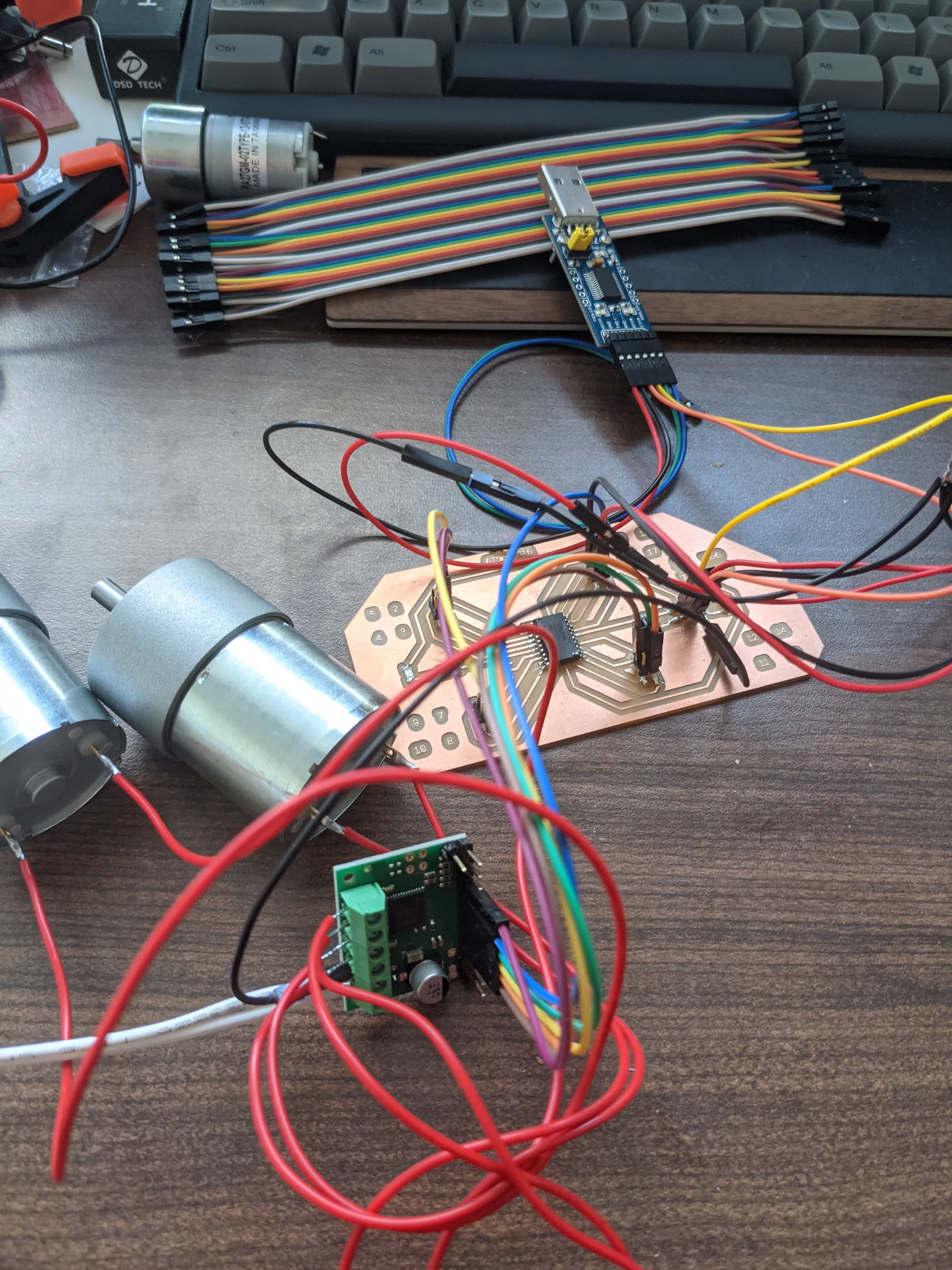
I know...it's a real mess. This is why we make dedicated boards, they are much neater and much less tangle prone.
Again, I am doing this to test which pins I want to use and for what, so bear with the messiness. The final project will look cleaner.
Programming Motor Board
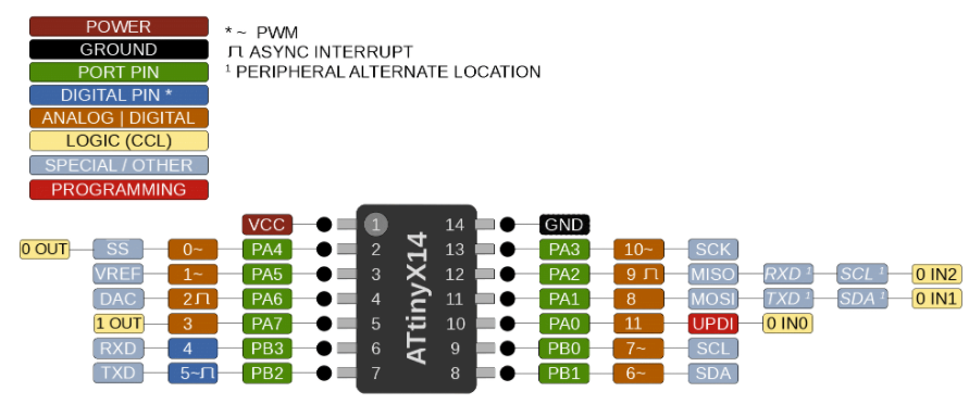
I am using this board to recieve the distance readings from the time of flight sensor board. Here is the ATtiny3216 schematic which may be helful when I explain what the program is doing: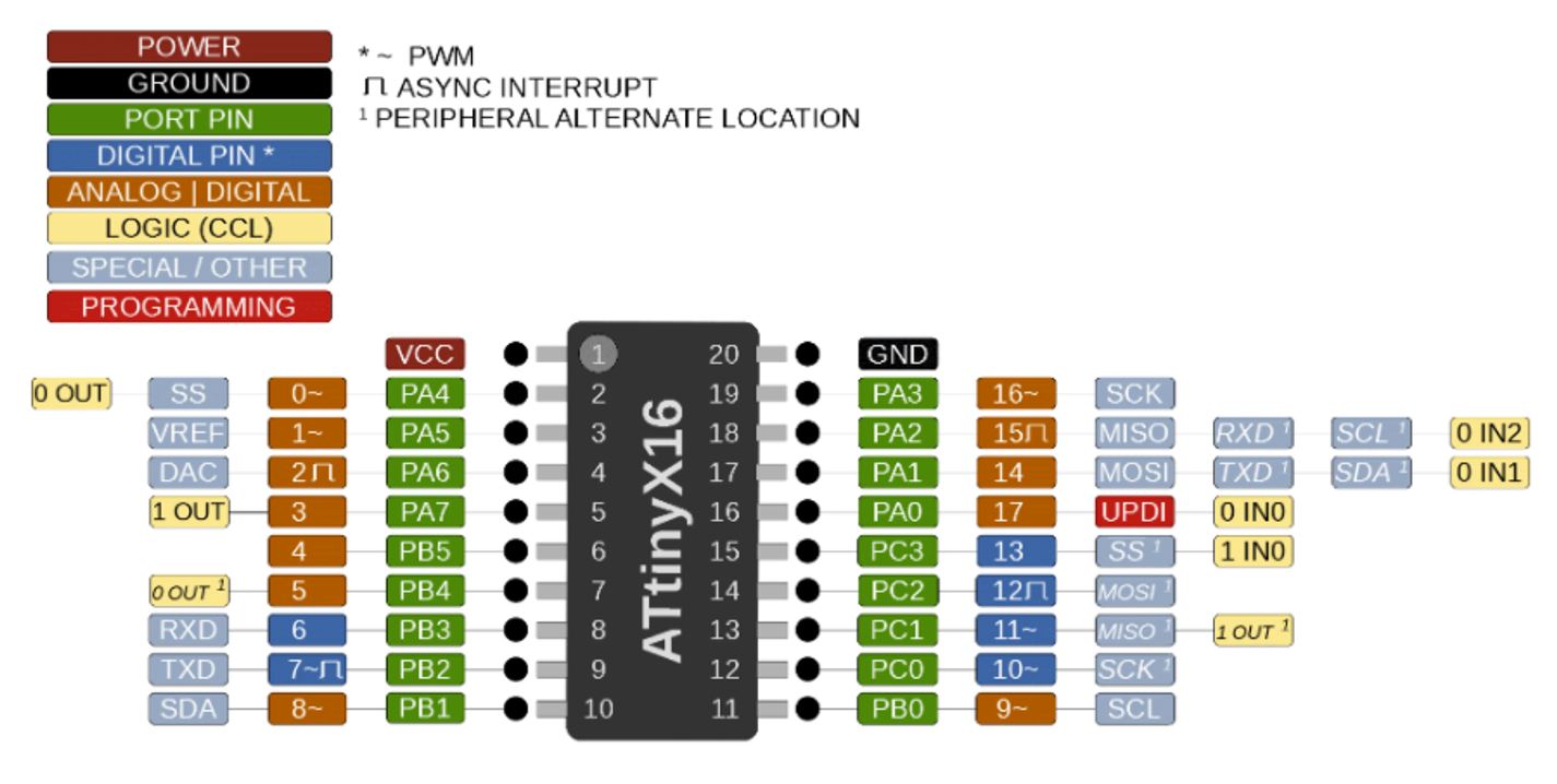
The structure of the program is as follows:
-include SofwareSerial.h and designate 2 pins to be the software serial RX and TX. I chose pins 19 and 18, respectively. I could have chosen any free pins for this.
-I defined all my variables. For example,
int LED=4; because the positive LED leg is connected to pin 6 on the microprocessor. Here are all the variables
I defined and their corresponding pins: INA1 on pin 12, INA2 on pin 13, INB1 on pin 14, INB2 on pin 15, PWMA on pin 2, PWMB on pin 3. I also defined a variable
called velocity which is a value between 0-255 to control the PWM to the motors, and I initialized a variable called distance to equal 0.-In the
void setup() , I began serial communication and begain the software serial communication. I set them both to have a baude rate of 115200. I
don't really know if that is fine, but that's what I did. I also used pinMode() to basically set all the pins as output pins. I included a
Serial.println("test") just for debugging purposes. I also turned on the LED here, also for debugging purposes.-In the
void loop(), I started off by using the listen() function to make sure the software serial was receiving data. I then made 2 IF
statements. ---->The first says that if the software serial is available (ie, the distance sensor is sending data), then use the
parseInt() function to
look for the next valid integer in case the clocks between the two boards are bit off, and store the distance value in the variable I called distance. I also
used Serial.println() to print that distance value on my PC. ---->The second IF statement is more of a testing/debugging tool. It says if a hardware serial is available, then do the same as above. Only difference is that I would feed the micro processor numbers from the Serial monitor on my computer, and those numbers would go into the distance variable. With these two IF's, I could either get the distance from the distance sensor on the other board, or feed it a fake number to make the motors run.
I then go on to another IF statement saying if the distance is greater than 500 (mm) then power the motors on, and if not, power them off.
Note: I discovered that my wall plug power supply was only capable of outputting 1A, and that this was not enough to power on 2 motors. So I did the above with 2 motors attached, but only powered on 1 motor when the distance was greater than 500. The sketch is here
.
Testing Motor Board
Here is a quick video showing a test where I execute the second IF statement. This is where I am feeding it fake distances from the serial monitor.You can see when I type in "501", the motor runs, and when I input "0", it stops, as it was programmed to do.
Setting up the Time of Flight Board
I made this board during the Output Devices week. It outputs distance, so it is technically an output device. In my configuration, however, I am using it as an input device. As a reminder, here is the schematic of the board: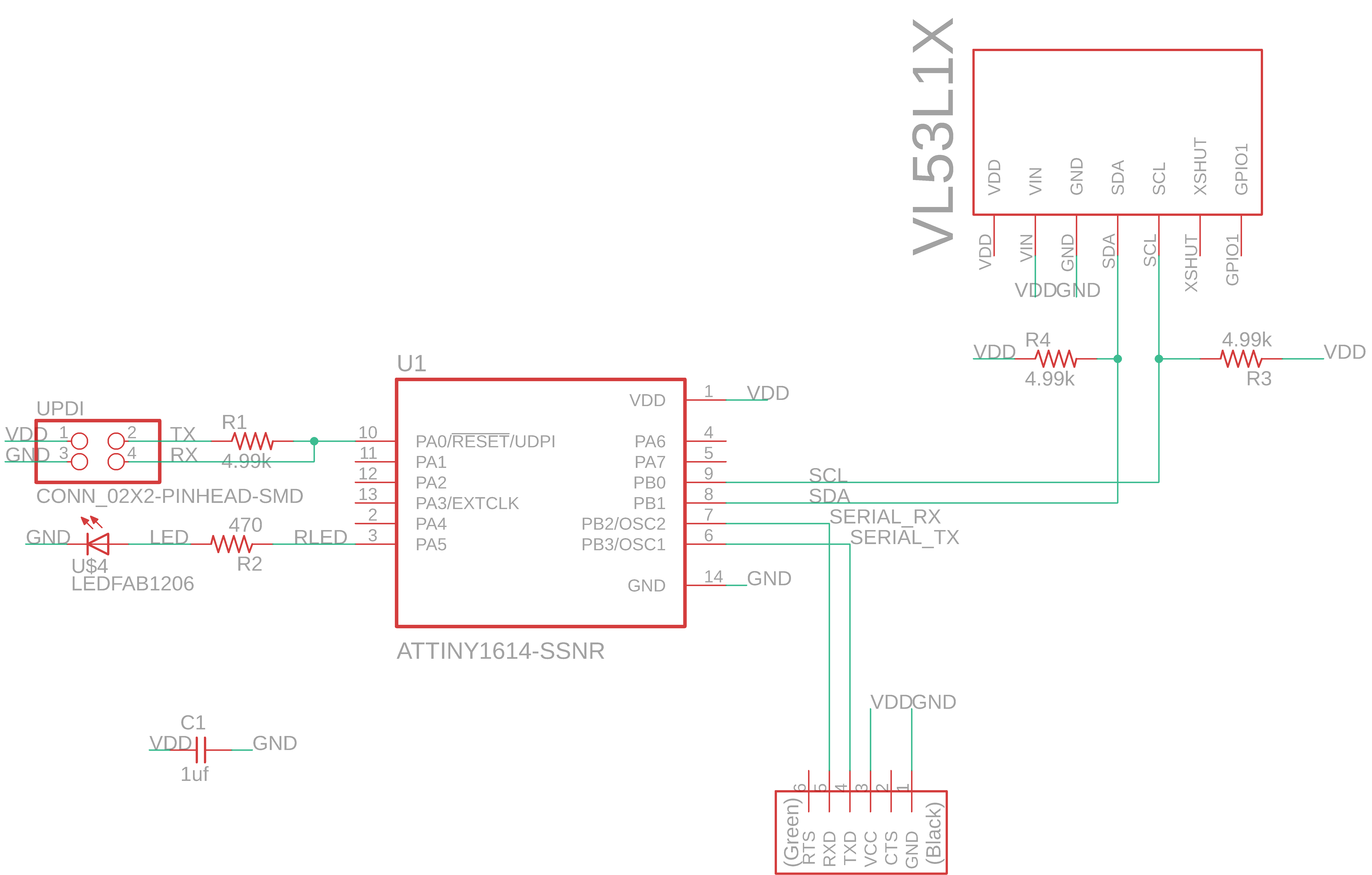
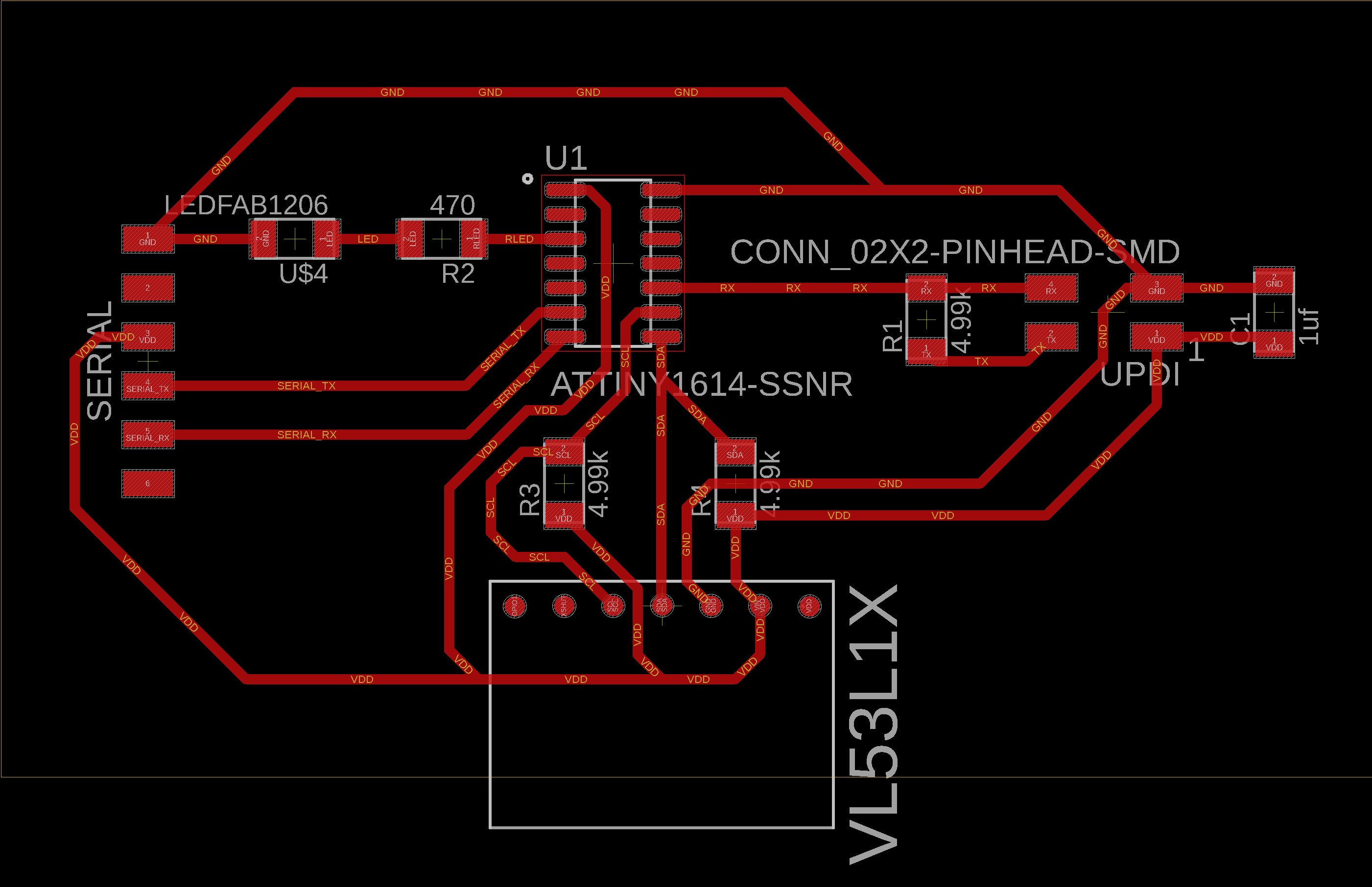
and here is the board layout:
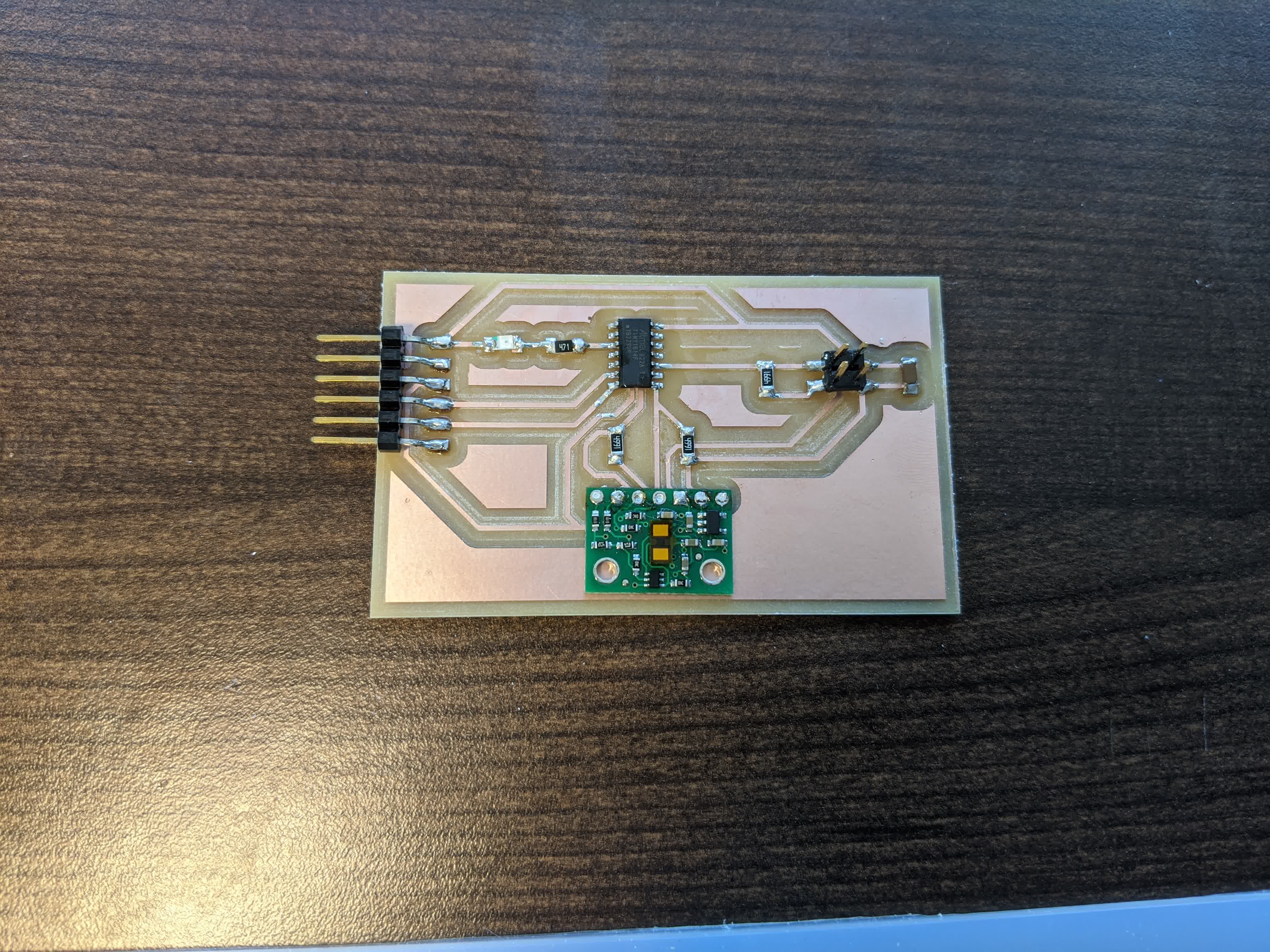
and here is what it looks like physically:
The VL53L1X time of flight sensor is on a carrier board and communicates with the ATtiny 1614 using the I2C protocol. For a wired connection between this board and the motor control board, I had 2 options:
1-serial communication
2-I2C communication
Using I2C communication might have been simpler; I think I only would have had to connect a wire from the SDA line on this board to the SDA pin on the 3216 (pin10), and another wire from the SCL line on this board to the SCL pin on the 3216 (pin11). However, as is shown above, I did not have any break out pins for that. In hind sight, I could have soldered pins onto the VL53L1x carrier board and then used that, or I could simply solder a male jumper wire pin into each of those through holes. In the end, I just did not want to mess with it.
So I went with the serial communication option because I already had pins breaking out of the TX and RX pins from the 1614 (pins 7 and 6, respectively).
Programming
The goal of this program is to have the ATtiny1614 communicate with the VL53L1X time of flight sensor using I2C protocol, but then send those readings out using serial communication to the other board. The structure of the program is as follows:-I start by including the Wire library as well as the VL53L1X library. The Wire library is used for the I2C communication within this board to allow the 1614 to communicate with the sensor. The VL53L1X library is handy because the manufacturer provided easy to use commands and variables to actually use the sensor.
-I define the sensor as "sensor" from the VL53L1X library, and also the pin where the single LED is mounted on the board.
-In
void setup(), I set the pinMode() of the LED as an output. I also begin serial communication at the same baude rate as the
other board (115200). I then begin the I2C communication using the Wire library and set the clock to 400kHz (which is the default from the manufacturer of the
sensor). I included a debugging IF statement to print out that the sensor is not detected in case there are issues there. Next, I used a few commands from the
VL53L1X library to setup the sensor. I set it up to be in long distance detection mode (4 meters), and gave it a time budget of 50,000 us to make a single
measurement. I then set it to start continuous readings at the same rate. Finally, once all that is done, I turn the LED on so I know that all the above went well.-In
void loop(), I only have 2 commands. First, using the VL53L1X library, I use the read() command to begin reading. Second, I
use Serial.println() of the distance readings (variable using the VL53L1X library) to lob those values over using serial communication.The sketch can be viwed here
. I programmed this using the UPDI pins on the board and it was ready to go.
Networking
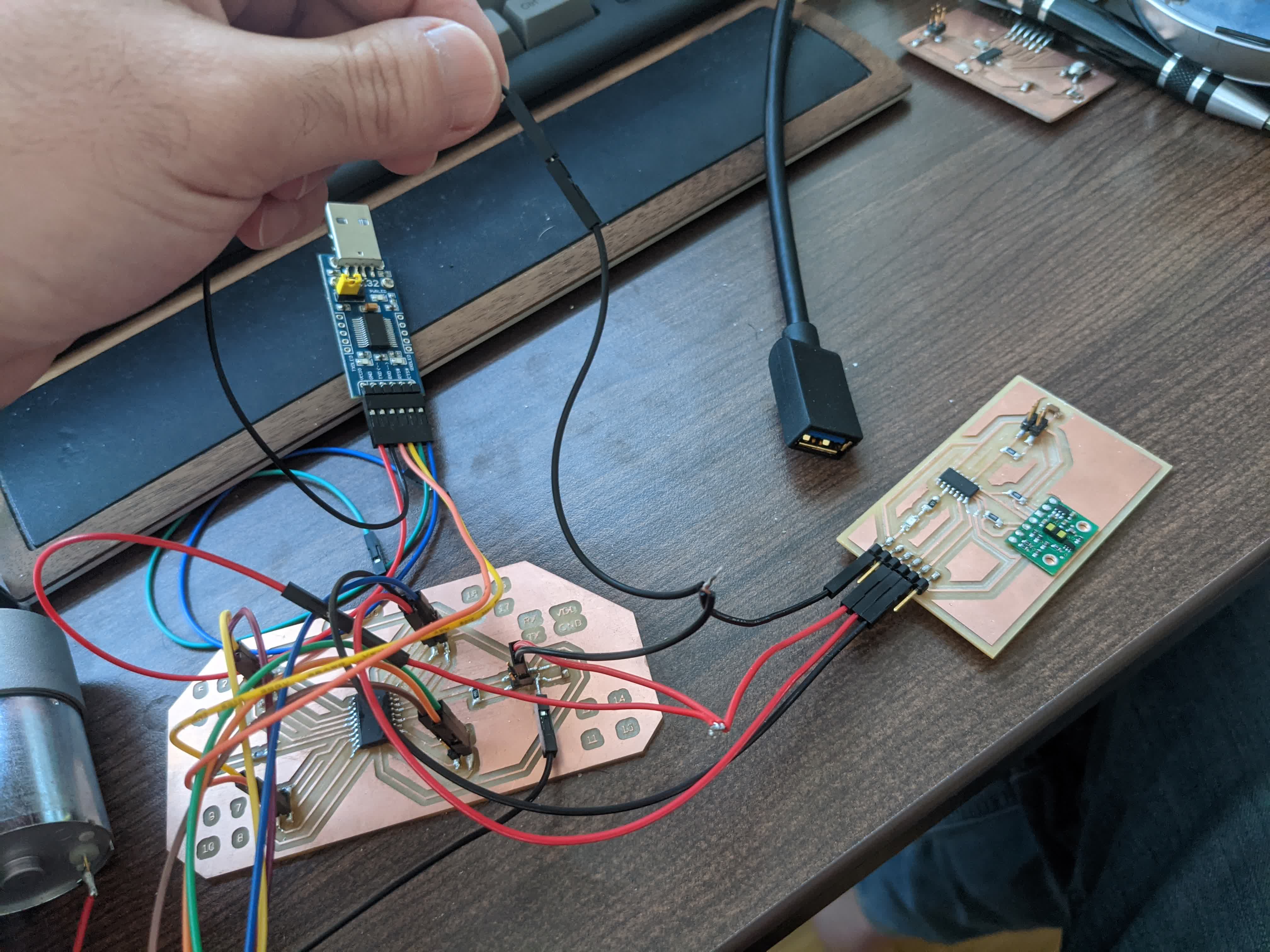
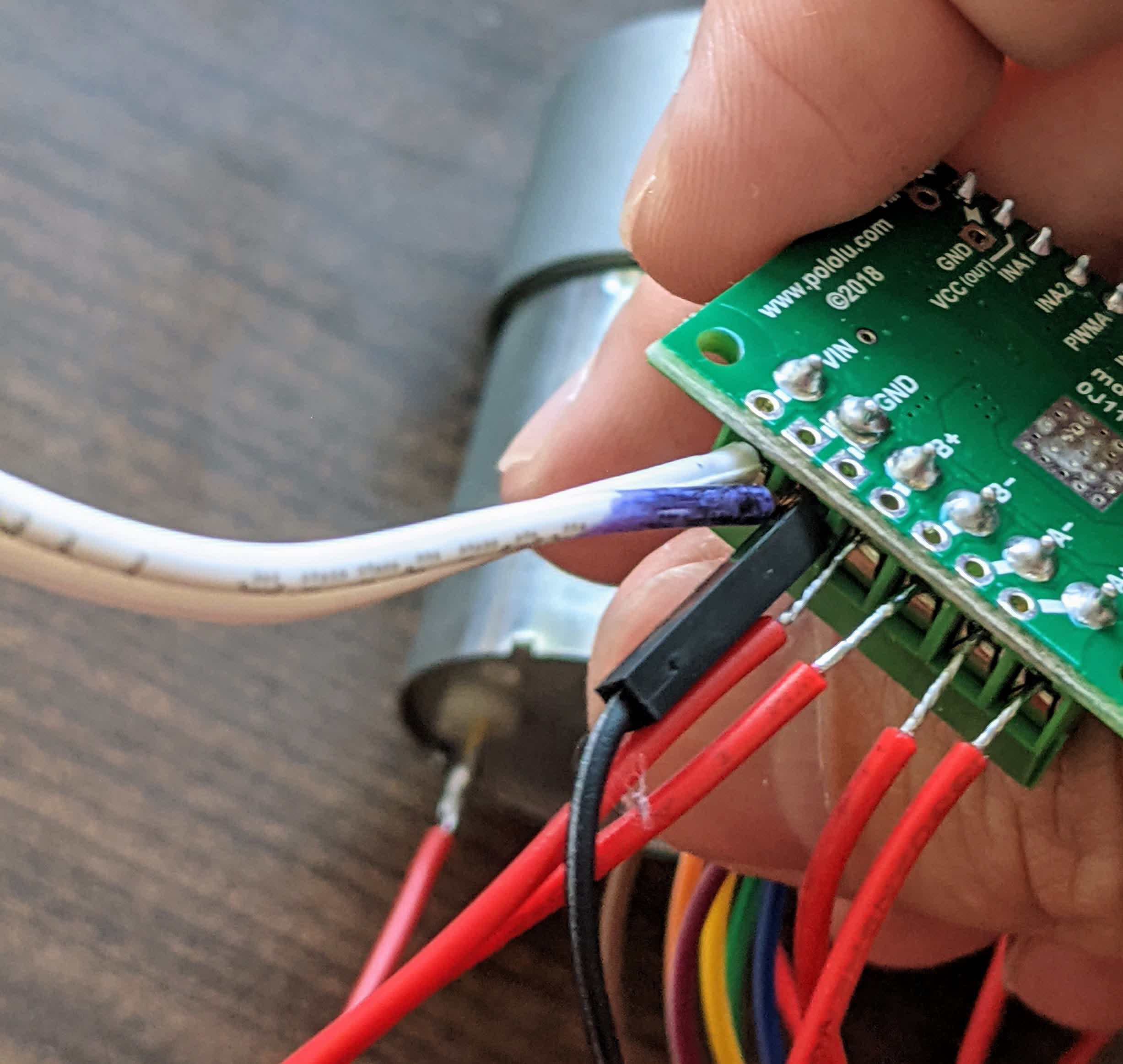
With both boards programmed and ready to go, all that was left was to physically connect them. Here is a schematic I made of the connections between the two boards along with the FT232 FTDI adapter, where the time of flight board is using the 1614 and the motor control board is using the 3216: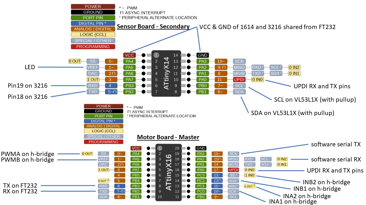
This is much easier to follow than the physical image:
The breadboard was there to connect to the LO1 and LO2 pins to the VCC out (with 10k resistors) on the dual channel h-bridge, and is only used to check for errors and is not necessary.
Connection Issues
Note: I ran into an issue, a dumb issue, but still an issue that took me a while to figure out. The motor board was getting power and ground from the FT232. The ToF board had no way of getting power and the same ground. The FT232 uses a female jumper connector which would normally go to the breakout pin on the boards. So I made a makeshift split wire with a single male connection and 2 female connections to split the signal to the two boards.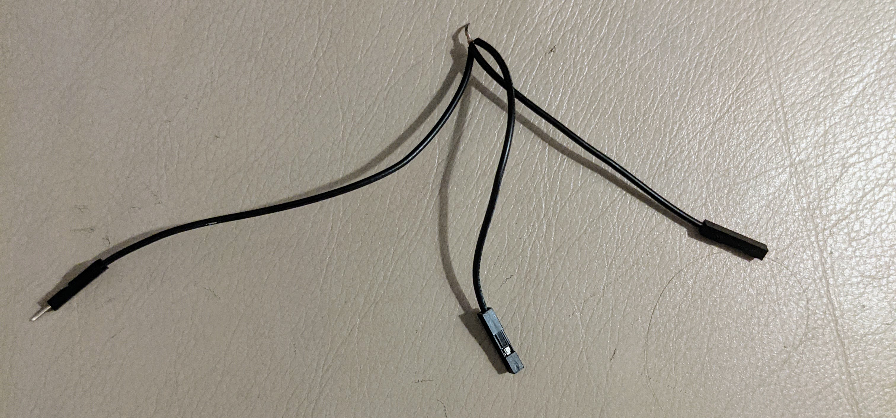
I did this by cutting a female-female jumper wire in half, and cutting off one of the male connections on a male-male jumper wire. This results in 3 wires: 2 females and 1 male. I stripped the cut ends, then twisted all the strands together, then soldered that connection.
Here is how it looks like with the male connection going into the FT232 ground wire, and the other 2 females plugging into the corresponding ground pins on both boards:
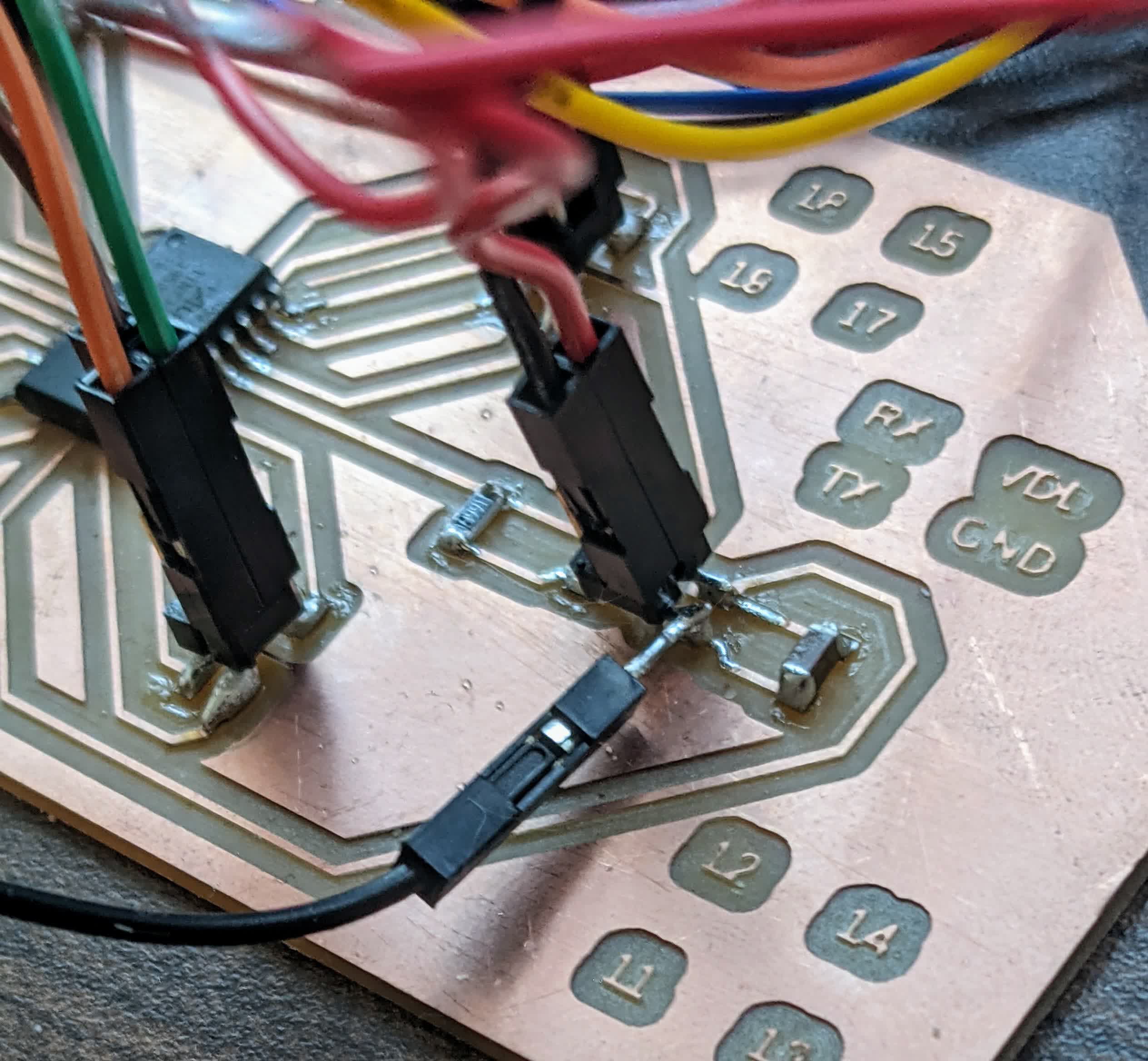
I did this for both power and ground. Another note: I didn't know much about ground loops, but they are apparently a thing you want to avoid. The H-bridge carrier board has a wall plug screw terminal for power and ground. However, everything must share the same ground. I realized this after I made my split wire, meaning I should have added another wire with a male connection to go into the ground screw terminal on the h-bridge carrier board. I did not do that, I instead used a male-male jumper wire, and tinned one end with solder, and soldered it to the mounting leg of the ground pin on the motor control board like so:
and stuffed the other male connection in with the wall plug's ground wire like so:
With that, I had power going to both boards and everything sharing a common ground avoiding potential ground loops.
Final note: I made a mistake connecting the TX and RX from the sensor board to the motor control board. I was mislead by my own drawing:
Here is the schematic of the ATtiny1614:
On the motor control board, I designated pin 18 as the software serial RX pin, and pin 19 as the software serial TX pin. This means that I need to connect pin 18 (software RX) from the motor control board to the TX pin on the sensor board, which is actually pin 7. As you can see in the footprint schematic, I have pin 7 labeled as RX. This is where perspective matters. Pin 7 is indeed TX from the 1614 perspective, it transmits, but from the PC's perspective, this is the RX pin because it is receiveing this data transmission.
To summarize, I had pins 18 (software RX) and 19 (software TX) on the motor board connected to pins 6 (RX) and 7 (TX), respectively. Meaning I connected software RX to RX, and software TX to TX. THIS DOES NOT WORK!! After swapping them, things worked fine.
so the correct configuration is this: pin 18 (software RX) on motor board connected to pin 7 (TX) on sensor board, and pin 19 (software TX) on motor board connected to pin 6 (RX) on sensor board.
It only took me 3 hours to degub this, but I finally figured it with Calvin's help!
Testing
With everything connected as described above, all that was left to do was plug in the FT232 to my PC's USB extension cable to begin communication between the boards, and to plug in the wall plug to power the motors with 12V.Here's a video showing it working:
The distance sensor is picking up on the distance to the ceiling which is greater than 500 mm, so the motor is running. I then place my hand between the sensor and the cieling making the distance readings less than 500 mm, so the motor stops. I also get a bit excited the second time I do this towards the end of the video knocking over my sensor board!
I just couldn't believe I got it to work!!
Things to Work On
Data Transfer Issue
I was so happy to get this running, however, my happiness did not last long. I discovered that the motor was stuttering when the sensor was stationary and pointed to the ceiling. I pulled up the serial monitor and saw what the sensor was sending over to the motor board from the motor board's side: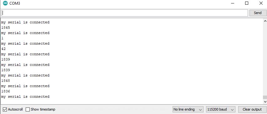
It became immediately apparent that every few readings or so, it was reading values less than 500 mm. I found this to be extremely odd since the sensor and the ceiling were not moving. I was not surprised by the bit of noise in the data; seeing 1845 mm and 1839, basically being a few mm of variation. Jumping to 1 and 42 was not right.
So I decided to disconnect and connect only to the sensor board, and here are the readings:
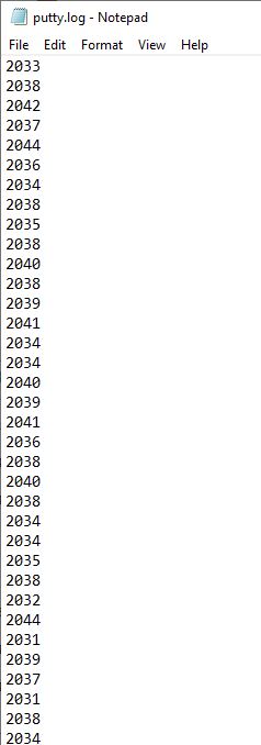
Yes, a little noisy, but consistent. Note, the ceiling height did change here hence the difference between these ~2030mm readings and the previous ~1840mm (I have a ledge on the cieling). So something seems likely wrong with the bit transfer going on, possibly with the
parseInt() function
and needs further debugging.Power Supply Issue
The wall plug power supply I am using can only output 12V at 1A. I observed that connecting both motors did not work, but running each individually does. So I am getting a 12V wall plug power supply capable of outputting 6A. I am confident this will be enough to power both motors simultaneously.However, I'm looking into getting a rechargeable battery pack to not have my stroller teathered to a wall. I haven't selected one yet, but ideally it needs to provide 12V, be capable of outputting the stall current of the motors (5.5A), and have a decent capacity to run for more than 5 minutes. Still a work in progress.
Programming
I think I am in a position now to start playing around with programming schemes/scenarios. I am thinking of the following:-run the motors forward when a distance is greater than 1m and when the distance is less than 0.5 m. This should allow it to follow and maintain distance away from an object moving in a straight line.
-If I have time, mount 2 more distance sensors to the left and right of this one to detect a change in direction. This should be straight forward using the I2C protocol, I would just need to connect SDA and SCL lines and power all the sesnors. I know these sensors have a field of view of 27 degrees. So I can do some math and see the optimum distance between them so that an object 1 m away is only visible to 1 sensor. So here is the example scenario:
1-If I am directly in front of it, only the middle sensor would detect me and both motors would run forward and back to maintain the distance.
2-If I move to the right, then the right sensor will pick on my distance from it, so I would lock the right motor and only move the left motor to steer the stroller right, until the middle sensor picks up on me again. Then go back to the forward/backward scenario.
If these two things work, I would call that a success. Yes, it is following indiscriminately, and yes, things may go wrong in the real world, but it is a start!
Files:
ATtiny3216 Traces gcode
ATtiny3216 Cutout gcode