Web Design, Version Control, and Final Project Brainstorm
Laser & Vinyl Cutting
3D Scanning and Printing
Make Something Big
Molding and Casting
Electronics Production
Electronics Design
Embedded Programming
Input Devices
Output Devices
Networking & Communications
Interface and Application Programming
Final Project
Group Assignment
The group assignment was to compare as many tool options as possible. This was done in collaboration with with Jordan, Maya, and Emma. The process and results can be viewed here.Interface and Application Programming
Assignment: Write an application that interfaces a user with an input and/or output device that you made.
My goal for this week was to create a user friendly interface for the VL53L1X. I will be using this sensor to control motors on my final project, and a simple user interface will help me to determine how sensitive the sensor is to ambient lighting conditions and how reliable the distance measurements it gives are.
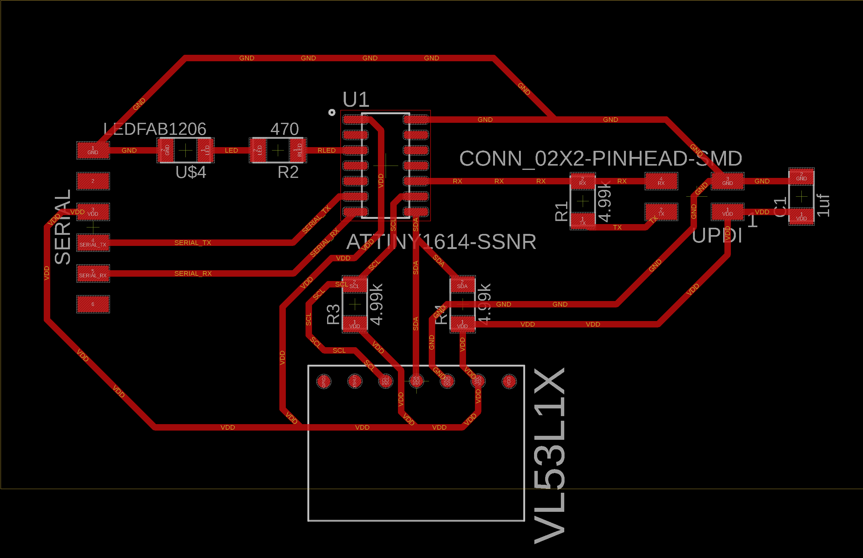
As a reminder, here is the board I am working with:
Setting Up
To create the interface, I chose to work with Processing. I was told it was similar to and compatible with the Arduino IDE. I am sure I could have achieved the same results with any of the other methods covered in the lecture, but I went with this.I started by downloading the latest version of Processing (v3.5.4 at time of writing this) from here. I then got acquainted with it by doing the "Hello Processing" tutorial. It seemed simple enough to use and was very similar to the Arduino IDE.
In addition, I found out that I can use an Arduino to program my microprocessor. I'll explain why this is helpful.
Up till now, I have been using the FTDI FT232 to upload my programs onto my microprocessor. My work flow was as follows:
-Connect FT232 power, ground, TX, and RX to the UPDI 2x2 pins on my board.
-Verify the program to generate the .hex file.
-Copy the hex file from the temp folder to the Arduino sketch folder
-Use the terminal to navigate to the sketch folder containing the hex file, and upload the program using pyupdi.
-Disconnect the TX and RX cables connected to the UPDI pins and connect them to the Serial TX and RX pins.
-Now I can check to see if the board is doing what it is supposed to be doing, and if I want to modify anything, go back to the first step.
This is a lengthy process.
I used this tutorial to turn my Arduino Uno into a programmer. It was well documented and straight forward. The basic idea with this new workflow is that I have the Arduino Uno connected to my board using jumper wires connecting the Arduino Uno's output 5V to my board's VCC pin, the Arduino Uno's ground to my board's ground pin, and the Arduino Uno's pin 6 connected to my board's UPDI RX pin. Simultaneously, I have the FT232 connected to my board using its jumper wires, where the FT232's TX is connected to the microprocessor's RX pin and the FT232's RX is connected to the microprocessor's TX pin. With this setup, I can set the port in the Arduino IDE to the Arduino port to directly upload a program from the Arduino IDE to the microprocessor, and then select the port connected to the FT232 to see the results and troubleshoot/debug.
I wish I knew about this before as it would have saved me time and been a much more efficient workflow to program and troubleshoot. My new workflow is as follows:
-Connect Arduino Uno power, ground, and pin 6 to the UPDI breakout pins (VCC, GND, and RX, respectively), and connect the FT232 TX and RX to my board's serial RX and TX, respectively.
-Select the port containing the Arduino Uno and upload my sketch directly from the Arduino IDE.
-Select the port containing the FT232 to see results.
-If I need to modify the sketch and reupload, I can do so in the Arduino IDE and upload after selecting the port connected to the Arduino Uno, then switch to the FT232 port to recheck.
Like that, minutes become seconds, and troubleshooting is much easier.
Programming the board
This board has been programmed and reprogrammed countless times so far. Once again, I am reprogramming it with the intention of outputting specific data. The tricky part is how to format the specific data I want to send. To my limitted knowledge, there are 2 ways to send any information:-
Serial.write(): Arduino documentation say that this sends binary data to the serial port. The data is sent as a byte or series of bytes. It also says to
send characters representing digits of a number, use the print() function instead.-
Serial.print(): Arduino documentation states that this prints data to the serial port as human-readable ASCII text. More details on data formatting can
be found here.Spoiler alert, I ended up going with
Serial.print(), and I'll get into that in a bit.Understanding Neil's Example
I followed Neil's example here which goes with writing binary data with framing. The issue I faced was on the listening end, having to put the numbers back together. This was a problem with the distance because it is a 16-bit integer, so it is being sent out in 2 chunks. I learned about the bit based & operator which does the bit-wise logical and operation between the distance and 255 (which is 8 one's in binary), so this would keep half of the 16 bit number the same. Here is an example to illustrate this; let us assume that the distance measured in binary is 0 1 1 0 1 0 0 1 1 0 1 1 0 0 1 1. This will be broken up in half: 0 1 1 0 1 0 0 1 / 1 0 1 1 0 0 1 1. Then the & operator acts between the right half and 255:1 0 1 1 0 0 1 1
& 1 1 1 1 1 1 1 1
= 1 0 1 1 0 0 1 1 , which is sent as a byte using
Serial.write()Then the opperation is repeated using the bit shift operator
>> 8, which does a shift to the next 8 bits, and then the bit-wise and is performed with 255:0 1 1 0 1 0 0 1
& 1 1 1 1 1 1 1 1
= 0 1 1 0 1 0 0 1 , which is sent as a second byte using
Serial.write().Note: I am unsure if what I am writing is 100% correct, my only uncertainty is if the first operation happens first or second; ie if the right half is operated on first. This would depend on how the bit-wise & operator works and how the bit shift works (left vs right). Regardless, this should not change the results.
Before doing the above, Neil sends the binary numbers: 1, 2, 3, and 4 for framing. He does this to make sure that on the listening end, we can identify each byte properly.
I then go over Neil's listening side here. I have never worked with Python, so it took me a while to translate into Java in Processing. Esseintially, what is happening is he has a while loop designed to find the framing numbers: 1, 2, 3, and 4. This framing scheme ensures that no matter what is being sent, it is nearly impossible that the first byte is equal to 1, the second byte is 2, the third byte is 3, and the fourth byte is 4. So when that happens, it breaks out of the while loop, and stores the fifth incoming byte as the
status (which is just a 0 if the range is valid
or some other 8-bit number documented in detail in the VL53L1X datasheet if the range is not valid), the sixth byte as low, and the seventh byte as high.
Then low and high are recombined as a 16-bit number in value which is the distance measurement.I was able to reproduce the sending part in the Arduino IDE and the listening part in Processing, but as I said above, I explored the option of using
Serial.print() as well.My Program
I really don't know if working in terms of bytes is more beneficial than working with human-readable characters. It was definitely a good excercise to go through, but I did end up going with human-readable characters.The structure of my program is as follows:
-I call the Wire library to allow I2C communication between my microprocessor and the sensor, and the VL53L1X library to allow me to use the user friendly commands and variables it provides. I defined the sensor as "sensor" using the VL53L1X library. I also defind the pin number that the on board LED is connected to on the microprocessor, which is physical pin 3 which translates to pin 1 in Arduino land.
-In the
void setup() function, I set the LED pin as an output and I begin serial communication as 115200 bps. I also begin the I2C communication at 400 kHz. I included a sensor
timeout clause and initiation along with a debug statement to know if it did not initialize properly. I then set my sensor to long distance mode (4m range) and gave it a time budget
of 140 m (ie how long it takes for it to take a measurement), and told it to start continuous measurements every 140 ms(this number should be greater than or equal to the time budget).
Finally, if all the above happens successfully, the LED should simply turn on to let me know that that setup process went smoothly.-In the
void loop() function, I use the read() function from the VL53L1X library to start taking continuous measurements. The next bit was the tricky part: sending the
data in an easy to work with way.I decided to work with a primitive way, but it works, so that's fine. First, I had to decide what I wanted to send, and I chose the following:
-the time (in ms), which is handy for knowing how long the board has been awake for, but also for potential velocity measurements which I may or may not do. I used the
millis() function for this.-the distance (in mm), which is the main point of using this sensor. This is a variable pulled from the VL53L1X library and written as
ranging_data.range_mm.-the measurement status, just in case I need to find the source of an error. The status is an 8-bit number, where 0 is good, and not zero means something is wrong. These are tabulated in the VL53L1X datasheet on pg 17. This is a variable pulled from the VL53L1X library and written as
ranging_data.range_status.-the peak signal count rate (in megacounts per second), to see how this changes as a function of distance and ambient lighting conditions. This is a variable pulled from the VL53L1X library and written as
ranging_data.peak_signal_count_rate_MCPS.-the ambient disgnal count rate (in megacounts per second), to quantify the ambient lighting conditions. This is a variable pulled from the VL53L1X library and written as
ranging_data.ambient_count_rate_MCPS.I do all this using
Serial.print() for each variable. However, to parse the data, I am also sending the "," character in between. Finally, the last bit of data sent, the ambient signal,
is sent using Serial.println(), and a newline character is sent to signal the end of a single cycle of data collection.Note, I did try doing all the above with a single
Serial.println() statement, but ran into issues because the data are not all the same format.The sketch file can be viewed here. Note that at the bottom of the sketch are helpful comments from the data sheet. In addition, I have Neil's version of the code commented there in case you want to try it for yourself. Simply comment out my serial prints and copy and paste Niel's code into the loop.
So that is done, and now we get to the actual point of this week's assignment, creating an interface!
Programming in Processing
I had to learn a bit about Processing before I got this interface up and running. Since I have my new workflow up and running, I had the Arduino IDE connected to the Arduino Uno port, and Processing communicating with the FT232 port. It made it easy to make a change in Arduino and immediately see the result in Processing without unhooking any cables.The idea I was going for was a window to open up and display the measurements in text, as well as have a circle changing in size based on a given measurement.
My program is structured as follows:
-I start by importing the serial library to allow serial communication, and creating my serial object. I also defind all the variables I want to use and initialize some of them.
-In the
void setup() function, I set the size of the interface window, defined the font I wanted to use, and began serial communication as the same baude rate of the microprocessor.-In the
void draw() function (which is the equivalent to Arduino's void loop() function), I define a string variable called "incoming" to read the incoming data until the
new line character using the readStringUntil() function. I then made an if statement saying that if the incoming data was not null, then a string array defined as "list" is
equal to the incoming data, and split whenever there is a "," character using the split() function. This parsed the array of incoming data which I then printed onto the terminal to view
using the println() function. I noticed I was getting some bad data, so I decided to filter it out with an if statement that would work when the sensor status parameter was "range valid".
In this statement, the action would be to store each incoming data piece into its appropriately named variable. That way, I would use these values, and I would only see them if the status was
"range valid".-Next, I set the background color to black, and used 2 main functions: the
text() function to display the variables, and the circle() function to graphically display the variable.
Another neat function I used was the map() function, which maps out a variable's value. For example, I know that the distance sensor reads from 0-3600 in long distance mode, so I mapped
that out to a scale from 0-400, where 400 pixels would be the largest diameter the circle can have. A big thanks to Calvin for introducing me to this and helping me with sparsing/desparsing the data.I did the above for the peak and ambient signals as well. It took a bit of trial and error to figure out the appropriate values for the circles and the positions of the text. The sketch file can be viewed here. Note that the translation of Neil's python code for decoding the incoming bytes is commented out at the bottom of the sketch.
The Big Reveal
Here is the result:On the left is a recording of the interface window, and on the right is a simultaneous recording of the sensor and myself. Initially, it is reading to a far away wall about 3m away. I then use a notebook moving it close and then slowly far away to show the distance value and the circle getting bigger as the distance measurement increases.
At about 40s into the video, I pull out a flashlight and shine it onto the sensor to show that the ambient signal measurement is working.
I noticed when measuring the distance of the notebook with the flash light still shining on the sensor, the ambient signal drops. This is reassuring letting me know that it won't be too influenced by measurements taken during the day vs night.
I also noticed that the peak signal spikes to ~40 MCPS for an instant, the moment an object comes into the field of view. This can be handy to know for when I plan to use multiple sensors and plan on setting up a steering module for my motors. I haven't decided how I would use it yet, but preliminarily, I can probably say to ignore incoming signals after a spike for a couple seconds before actually taking the distance value as an input for motor control.
This user interface was definitely helpful in allowing me to see what the sensor sees and figure out a plan in how to use it. Now I'm off to figure out that plan!