Web Design, Version Control, and Final Project Brainstorm
Laser & Vinyl Cutting
3D Scanning and Printing
Make Something Big
Molding and Casting
Electronics Production
Electronics Design
Embedded Programming
Input Devices
Output Devices
Networking & Communications
Interface and Application Programming
Final Project
Group Assignment
The group assignment was to measure the power consumption of an output device. This was done in collaboration with with Jordan, Maya, and Emma. The process and results can be viewed here.Output Devices
Assignment: Add an output device to a microcontroller board you've designed, and program it to do something.
I made 2 output devices this week:
1- a light remote capable of emitting red light and IR light
2- a motor board with a phototransistor that can run the motor based on the level of visible light
3- I also made a board for the VL53L1X which measures distance (I don't know if this counts as output, it's outputting distance so I'm calling it output)
Light Remote
In the case I go with the phototransistors, I thought I'd make my own light remote, with a button which powers on a red LED and another button which powers on an IR LED. If I choose to go this route, then I can program the emitted light to be modulated so that the phototransistor on my board from input devices picks up on this without ambient light.For now though, a simple on/off sounds good to start things off. Also note, I am pretty excited about this because I am making a standalone device not teathered to any cables.
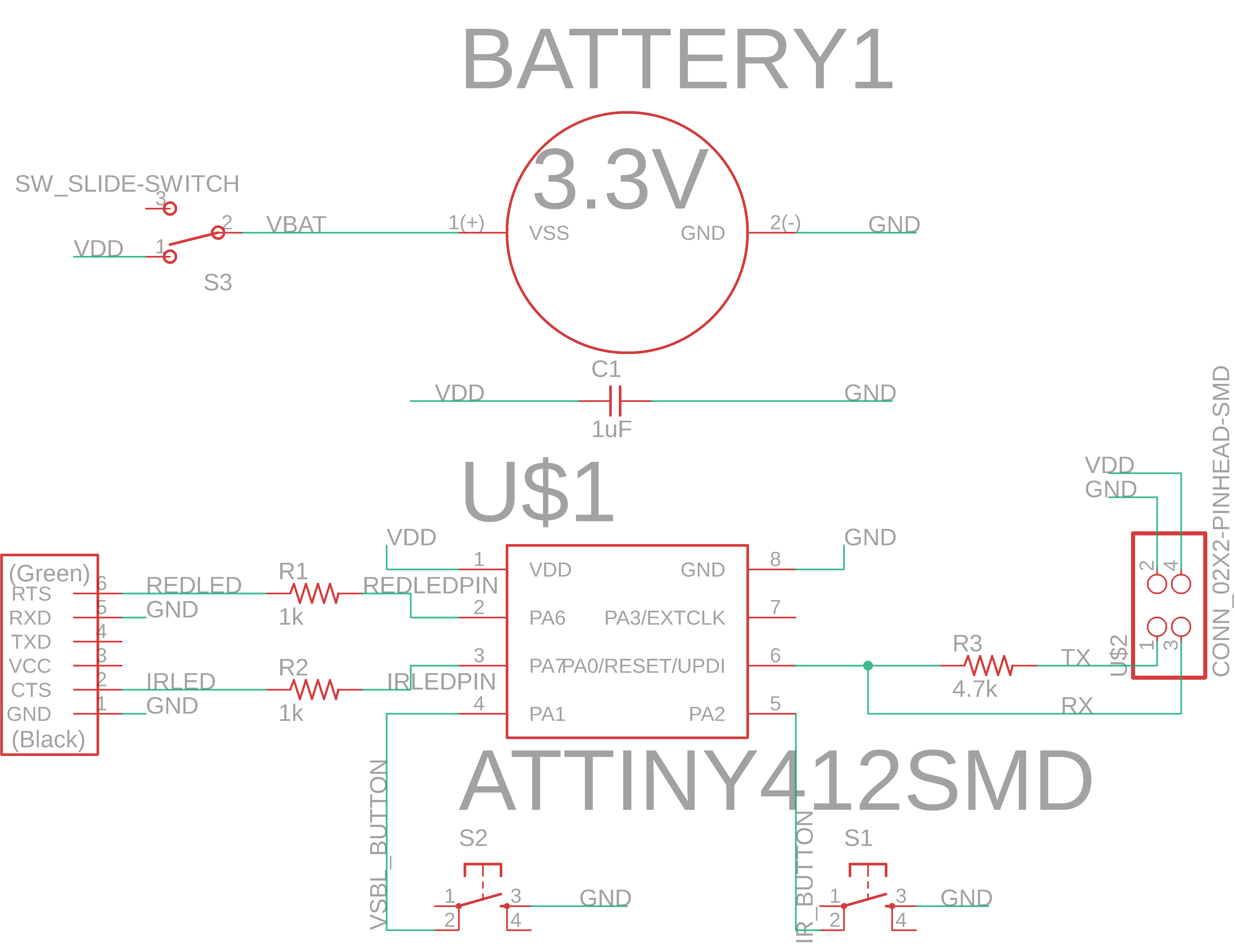
Here is the circuit schematic:
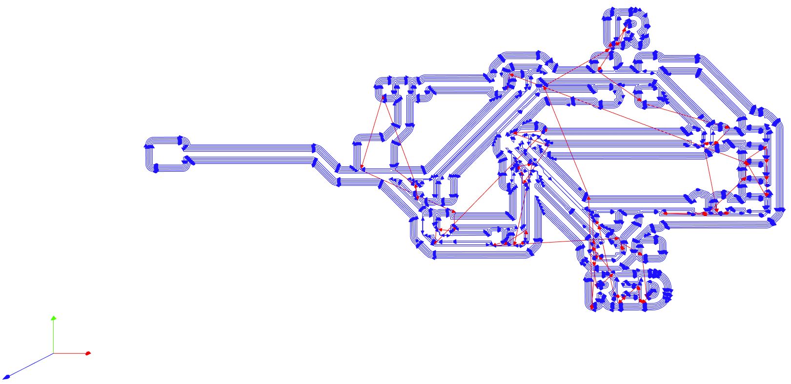
Here is the board layout:
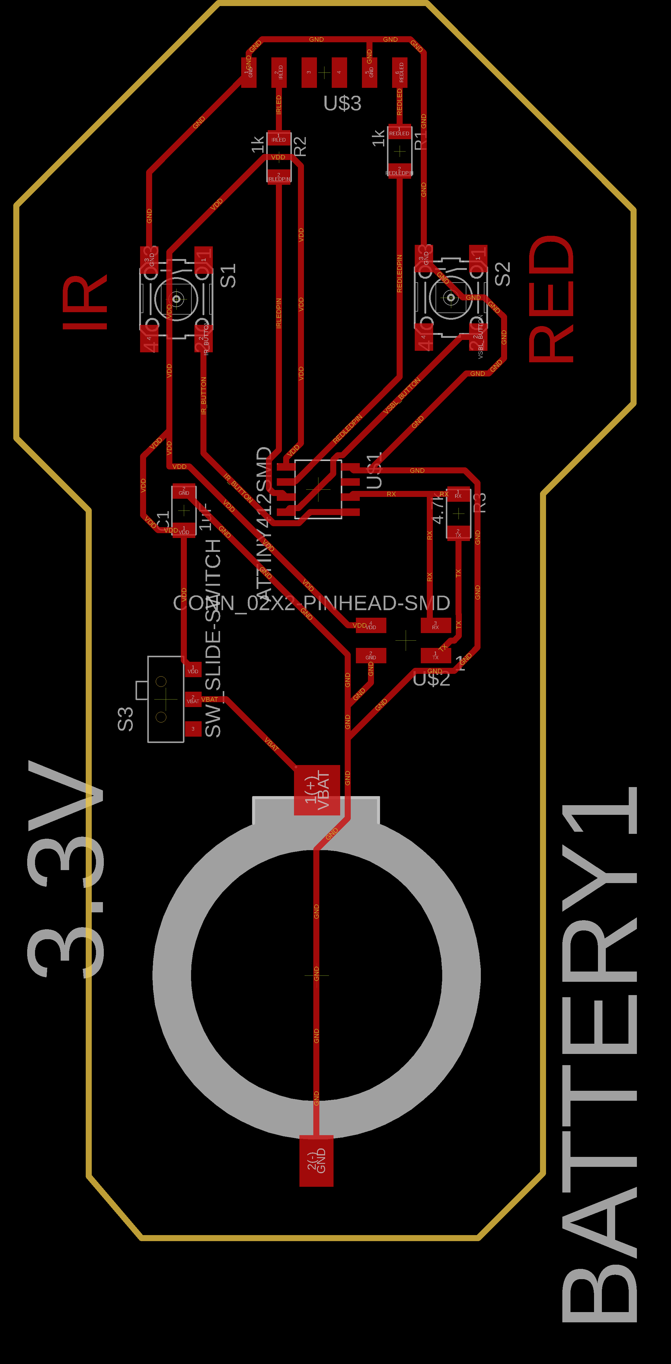
I'm particularly excited about the battery which I made a custom part for in Eagle as described in Input Devices. Also note the FTDI header pins I put on top. These are not actually FTDI headers, I'm using the pins and then will solder the LED's between 2 pins. I found that the LED's fit snuggly between 2 pins after prying them open a bit.
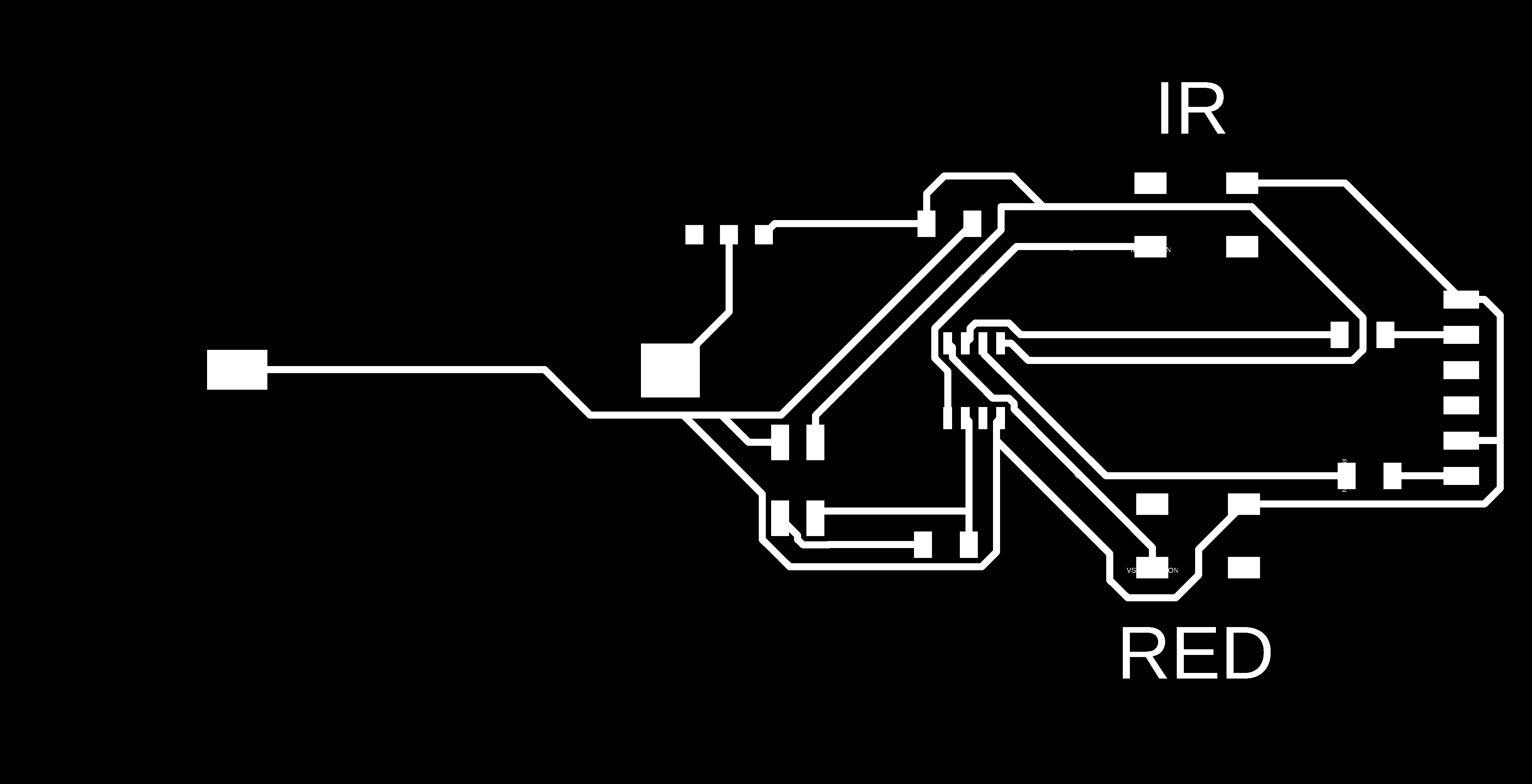
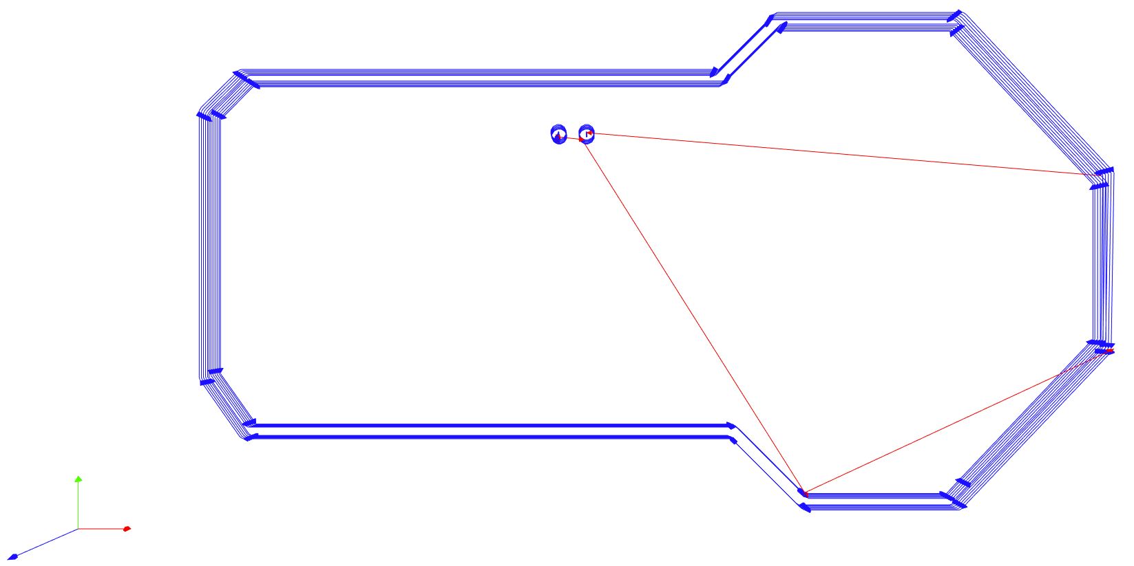
Here are the traces:
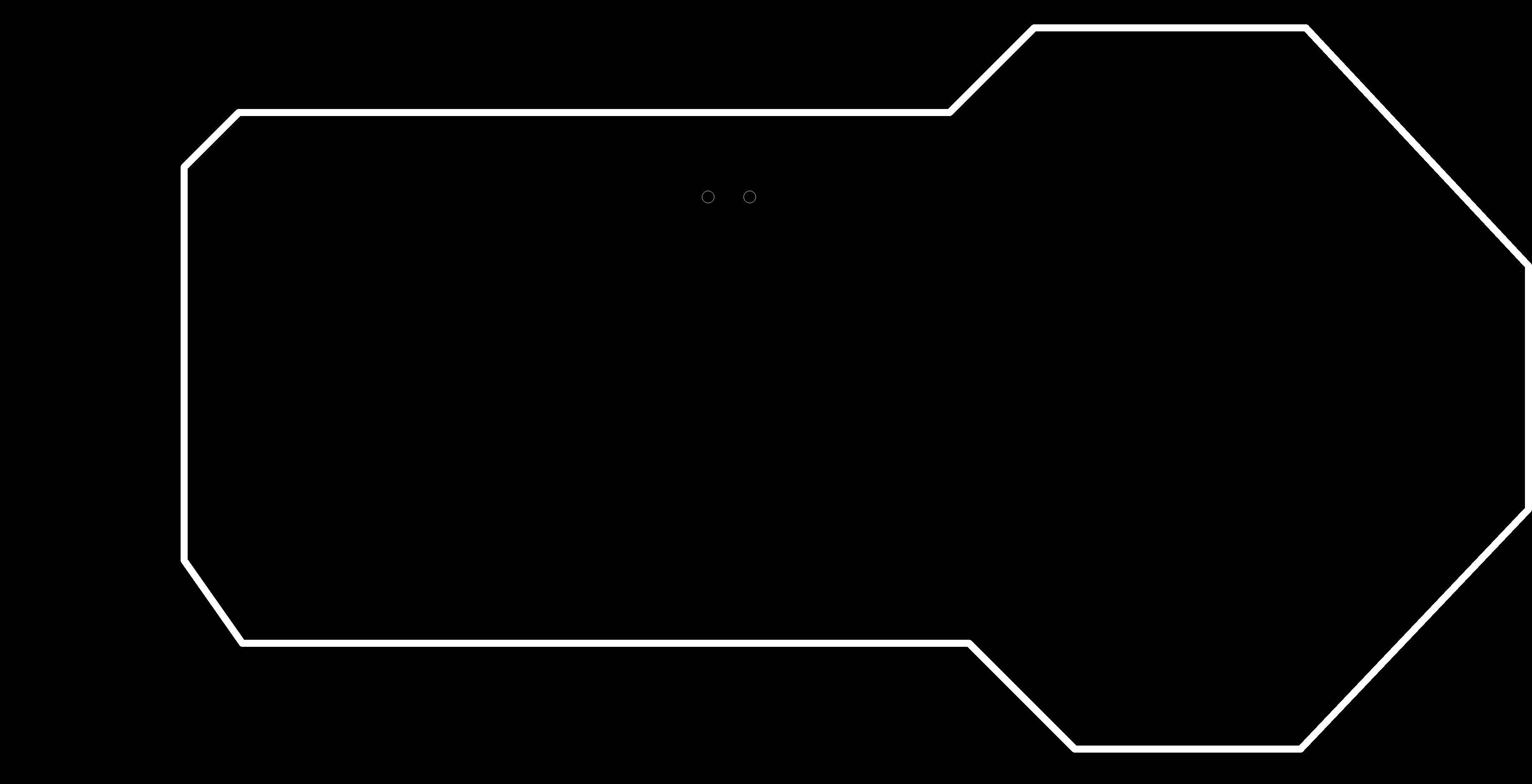
Here is the cutout:
I put these into mods and used the 1/64" flat endmill to cut 0.004" and 5 offsets at 2.5 in/s and generated the gcode. Here's the toolpath:
For the cutout, I used the 1/32" flat endmill to cut in 0.01" increments to a maximum depth of 0.06" at 2.5 in/s and generated its gcode. Here's the toolpath:
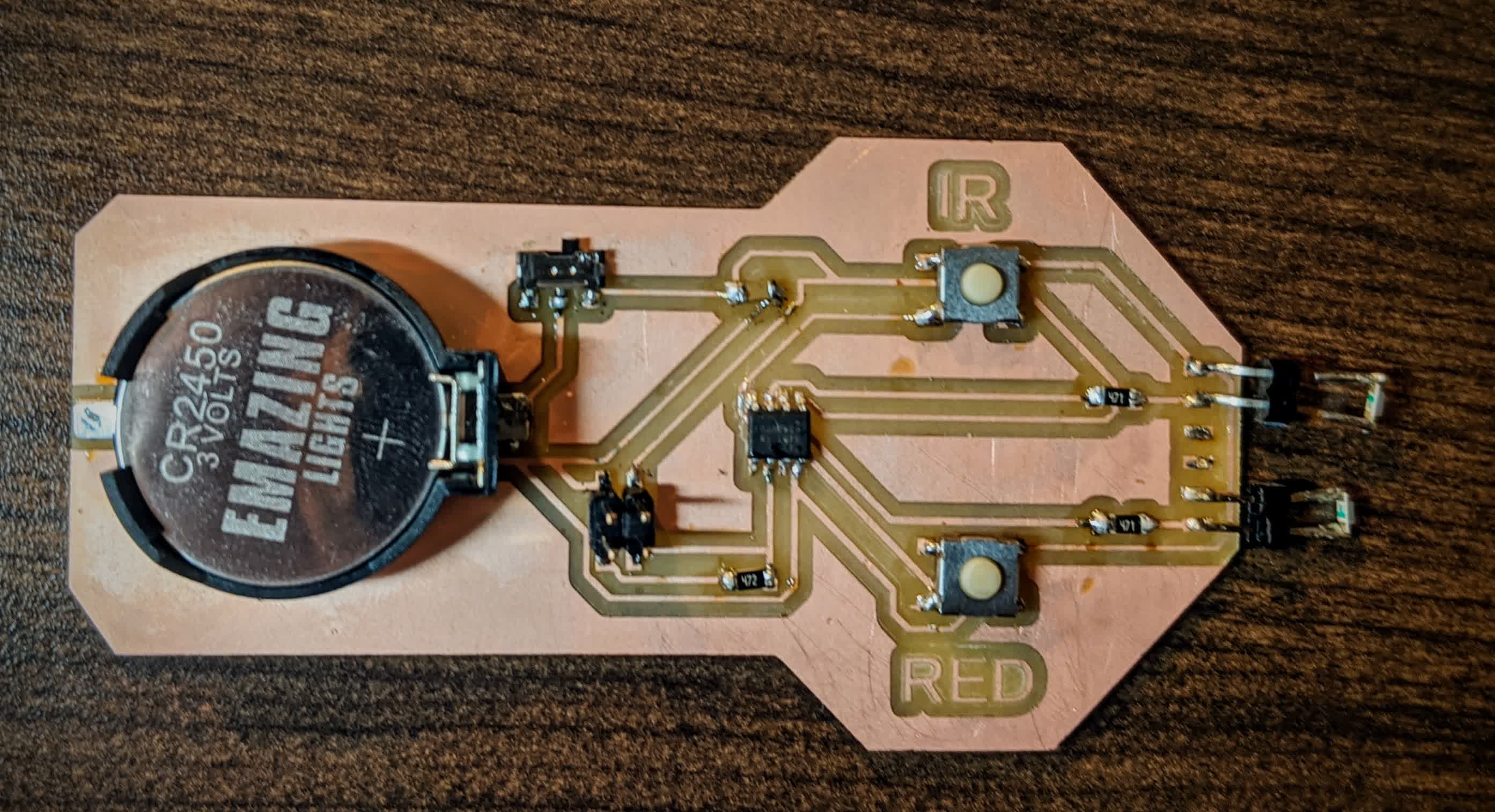
After soldering on the components, here is the end result:
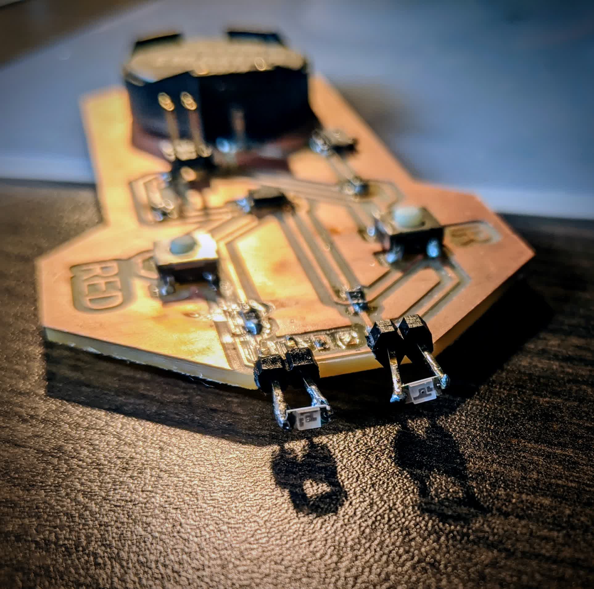
and here is an isometric view for a better look at the LED's:
The sketch can be viwed here. It was programed to turn on the LED while the "red" button is pushed, and turn on the IR LED while the "IR" button is pushed. Here is a demonstration:
Like I said, I may or may not use this in my final project. In case I don't, I've at least put a smile on my daughter's face.

She absolutely loves pushing buttons, so she is quite happy with this!
Light Controlled Motor
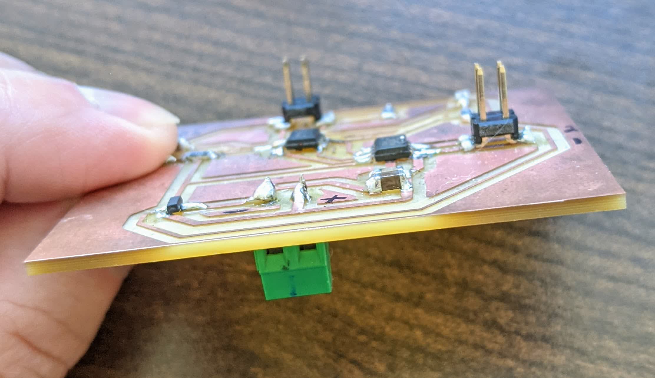
The next project I worked on was making a board that controls a motor based on light. This was my first time working with a motor, and so I was excited, especially since it is important for my final project. The board I designed this week has a screw terminal for a 12V wall plug to power the motor, a regulator to step that voltage down to 5V to power the rest of the board, an H-bridge to control the motor, and a phototransistor to use as an input for the motor. Here is a schematic of the board: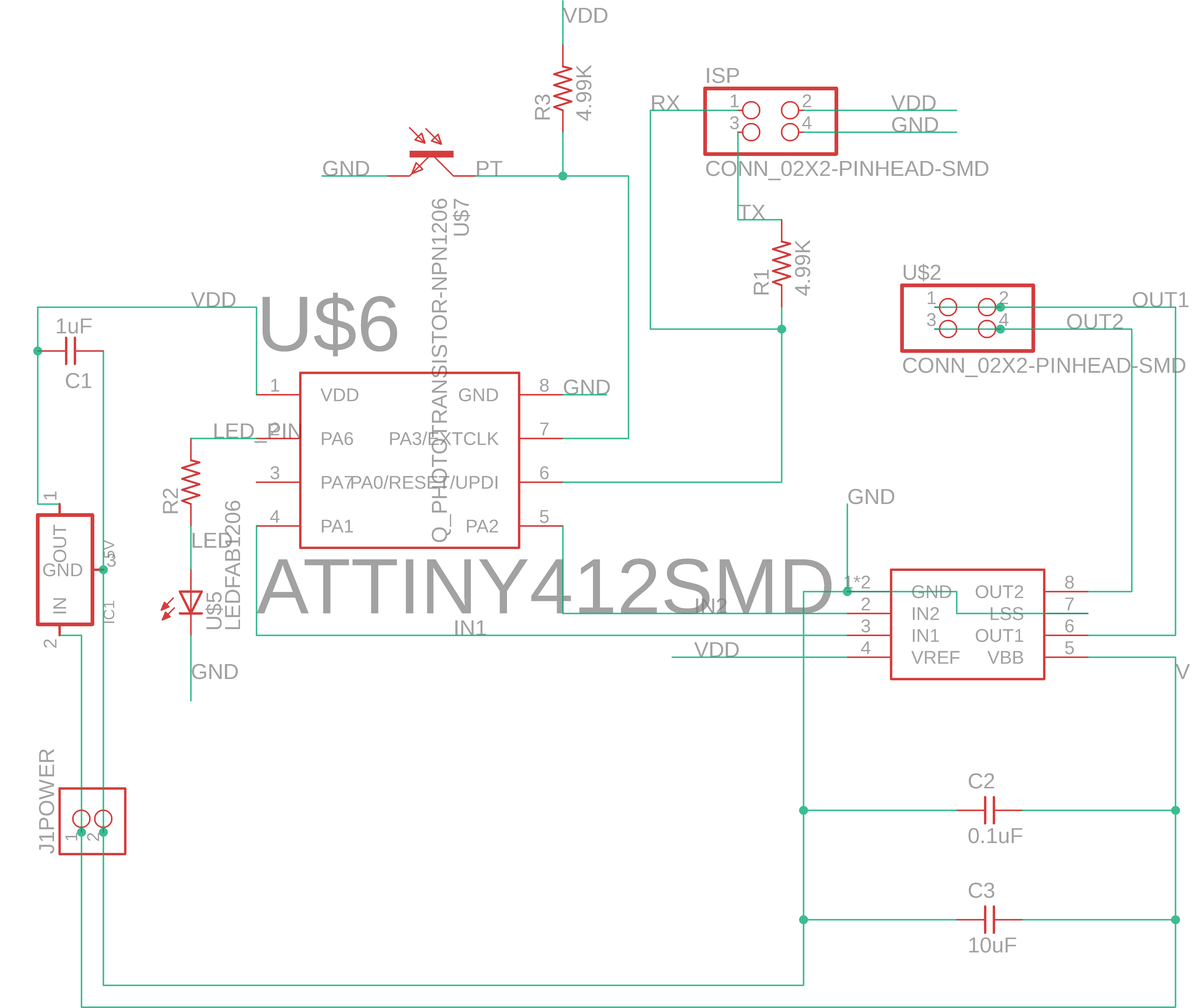
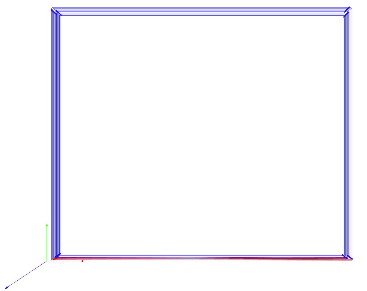
Here is the layout of the board:
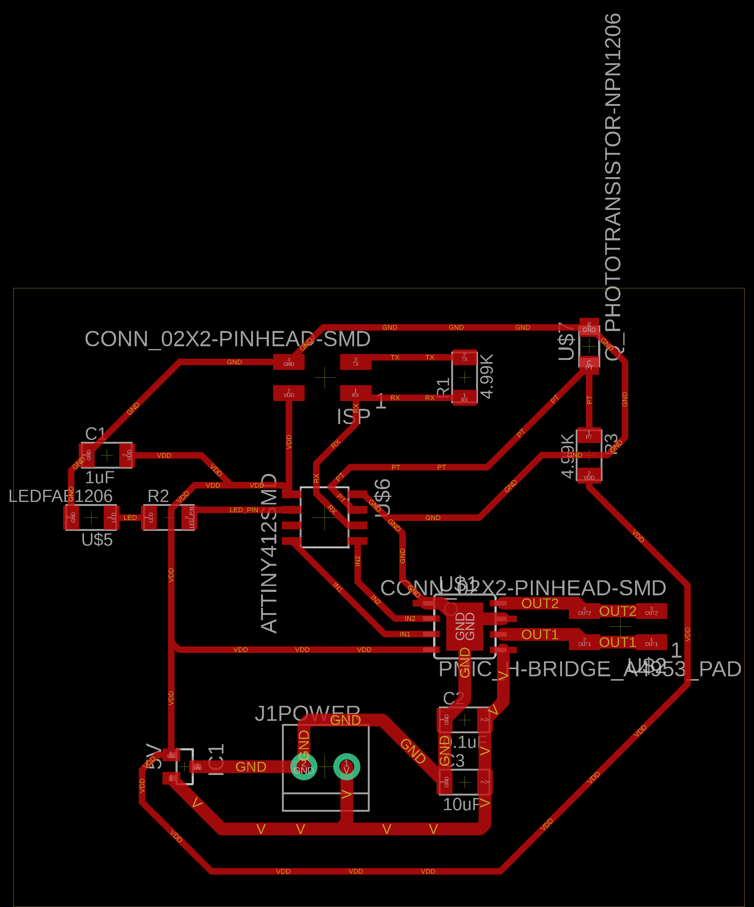
The only thing not shown here is the motor which I got from Zach. I just had the model number on the motor: RA27GM-02TYPE-12-1/77-R. I looked up the datasheet online and found this. This helped me understand what I was working with.
The motor runs on 12V, and has a reduction ratio of 1:77. So this motor was rated for 0.8 kg-cm, and 46 rpm. It pulls 50 mA under no load and up to 150 mA under load. After finding this out, I already knew that this would be a problem for my final project. I don't know if it can drive the big stroller, but for now, I am going through the exercise to understand motors and how to control them better. For my final project, I'd probably just have to tune the board a bit to accomadate a beefier motor. Here are the traces of this board:
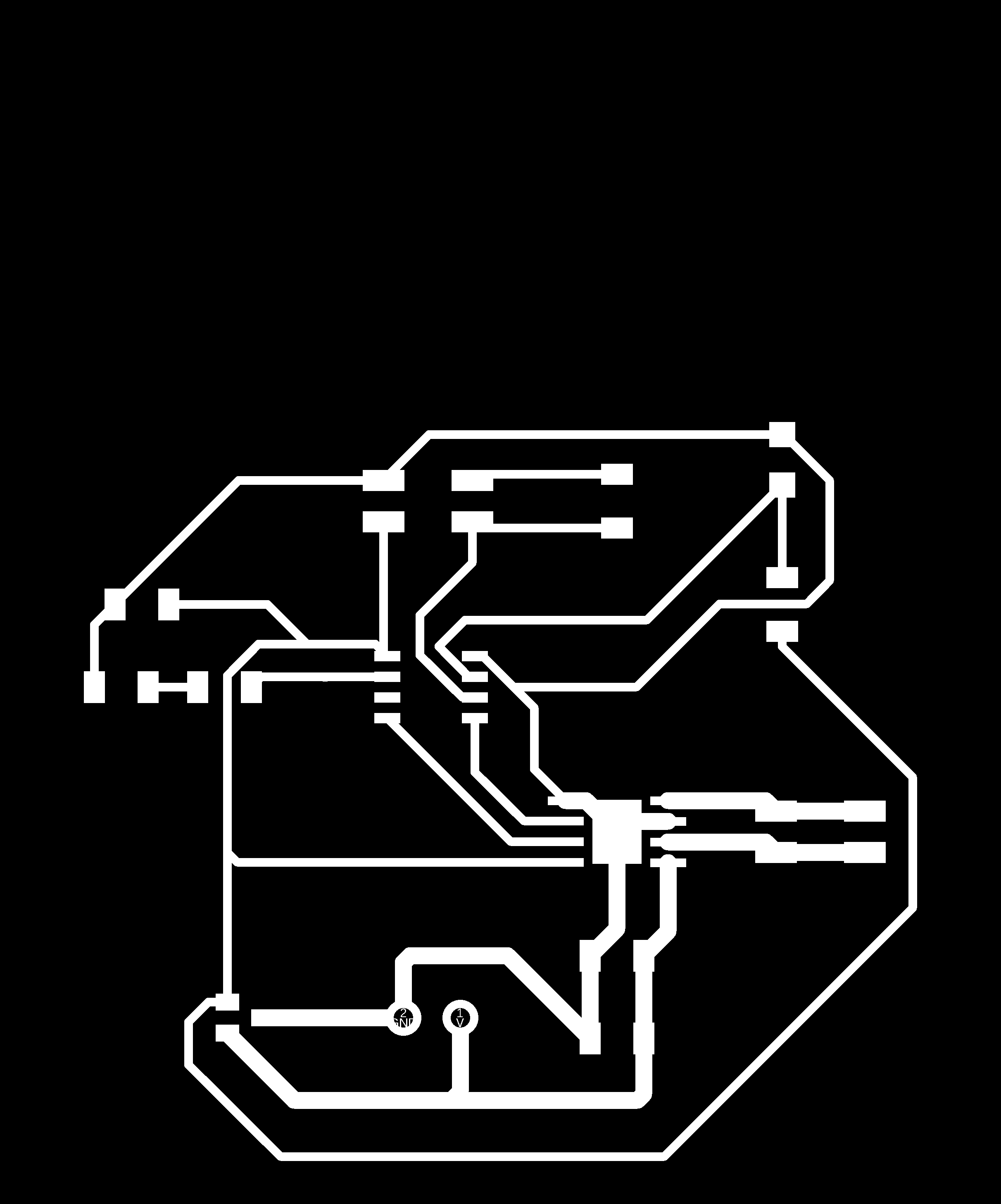
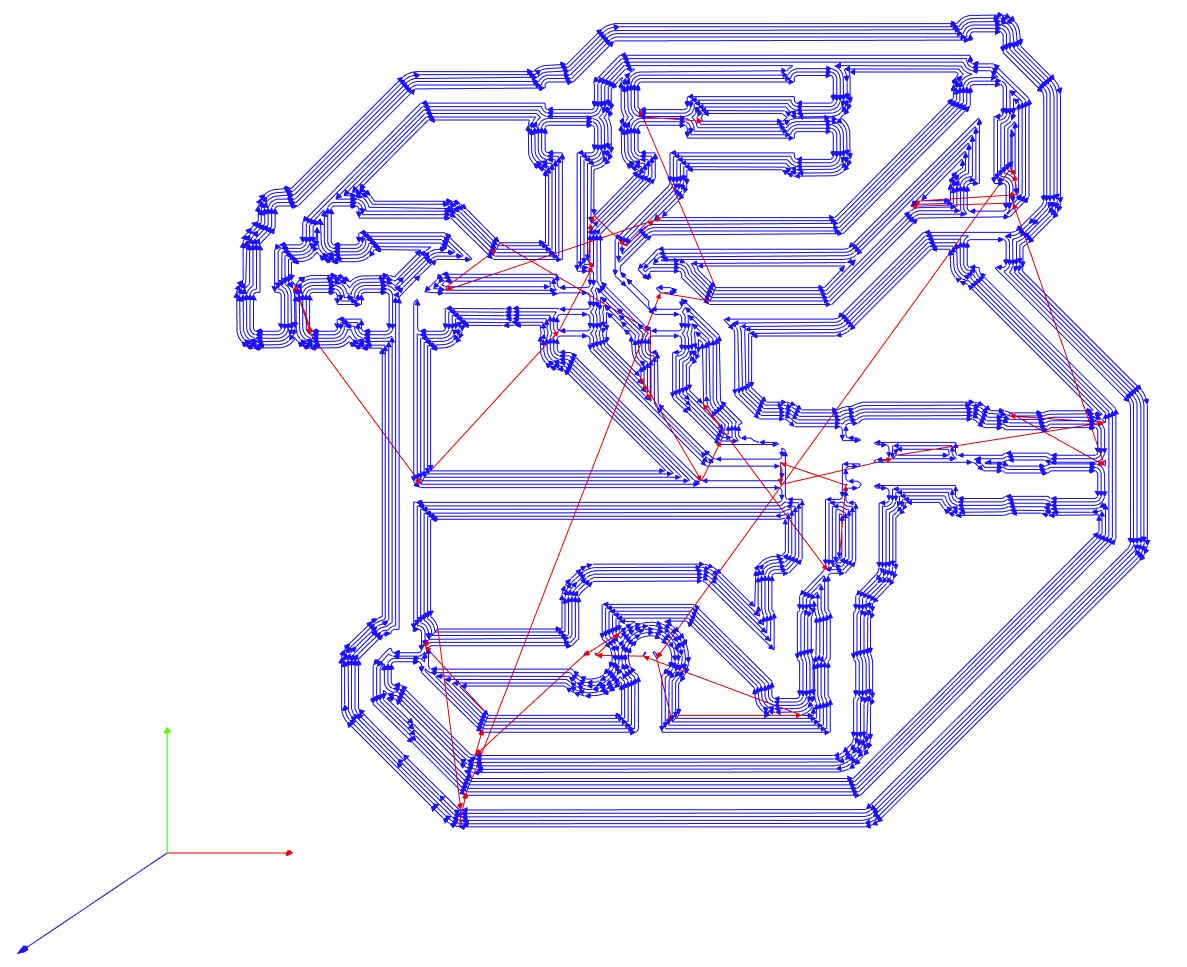
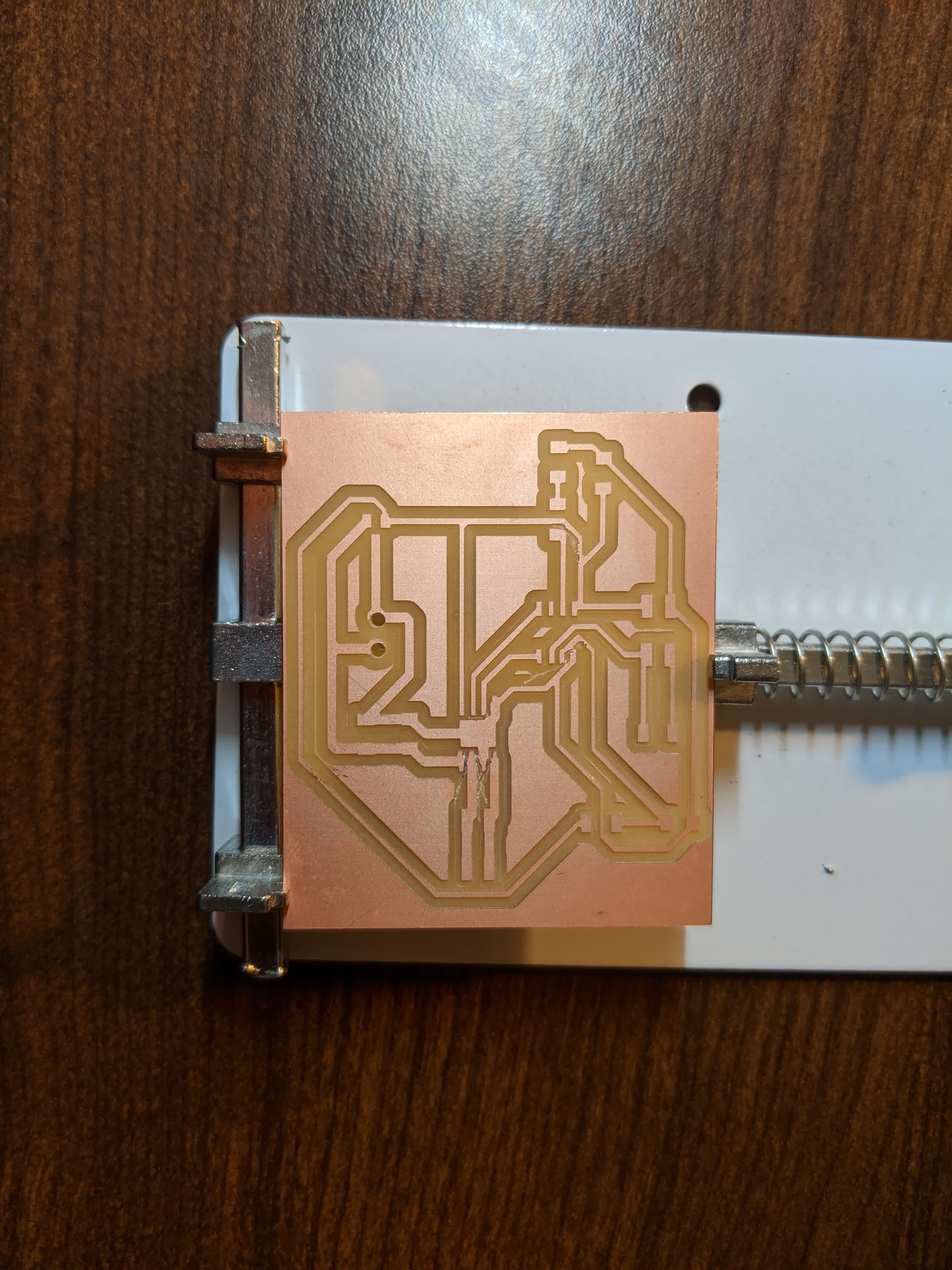
Here is the cutout:

I messed up at this point and should have included the screw terminal holes in the cutout to drill, but I didn't. I realized later and just used a hand drill for this. I used the same mods settings as above to generate the gcode and toolpathes for the traces and cutout:
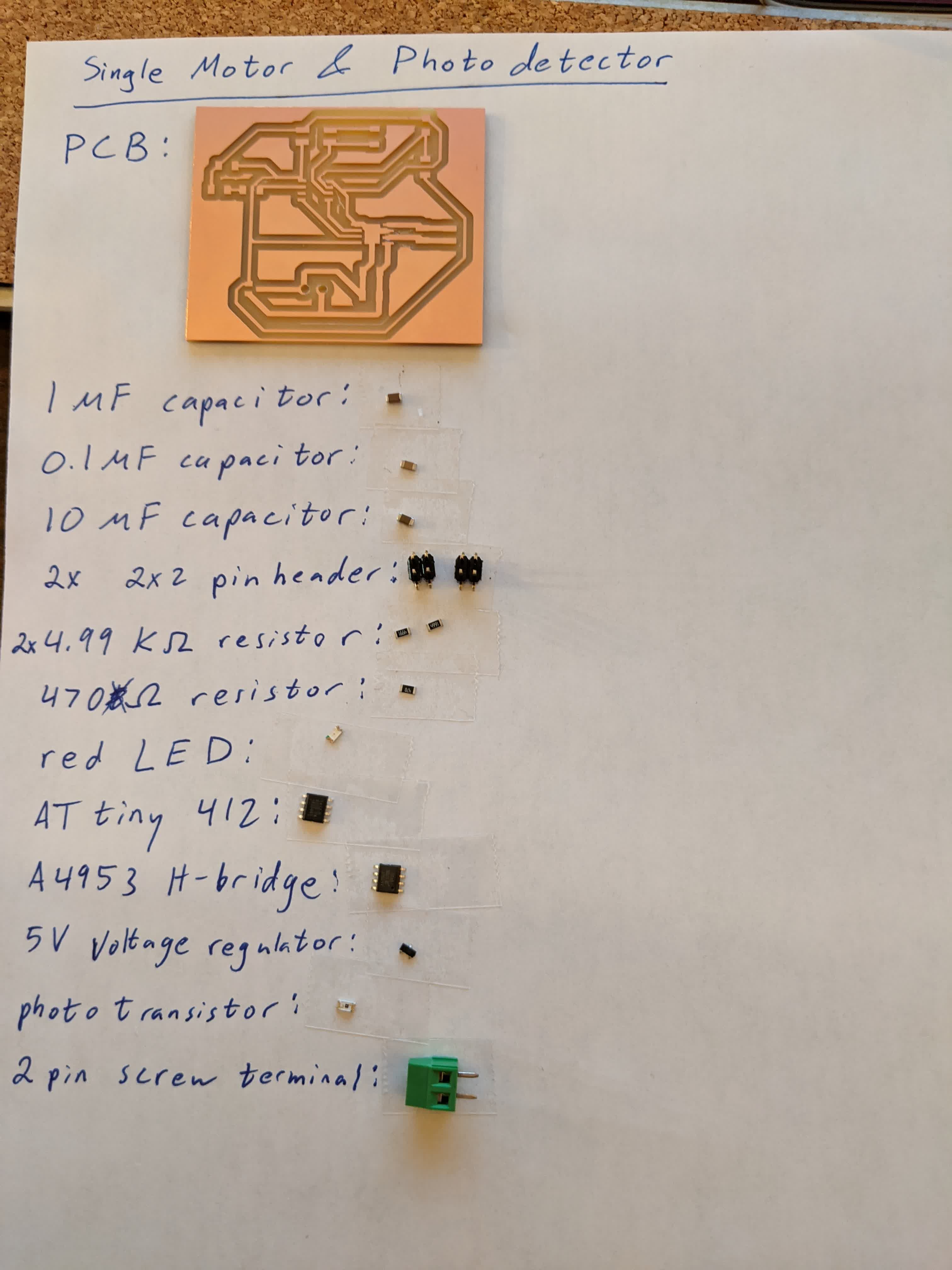
Once I cutout the board, I layed out all the components:
Here I am showing the board before soldering, but after drilling out the screw terminal holes using the hand drill:
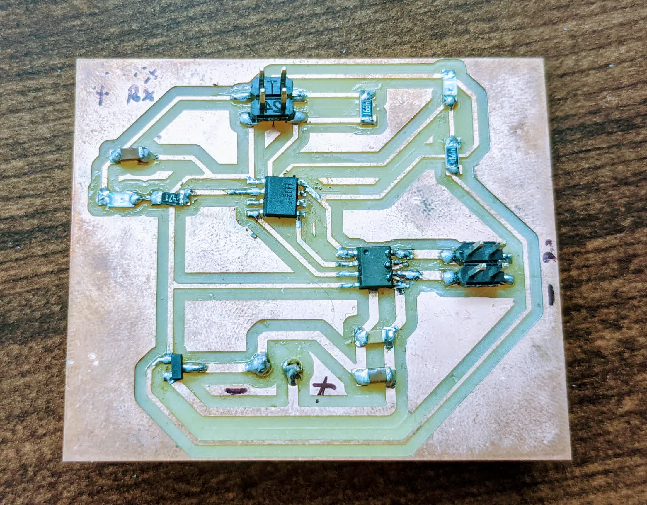
I forgot to take a picture of the board immediately after and I'm including this now, showing the board with all its components. Yes, it got a little dirty, but still works.
I was also wondering if there was a way to mount the screw terminal on top of the board. When I did, I could not seem to get a good solder connection between the individual screw terminals and their corresponding traces. Mounting it on the bottom works just fine though.
I used my oscilloscope to see the signal being read by the phototransistor. Here is the signal with no light:
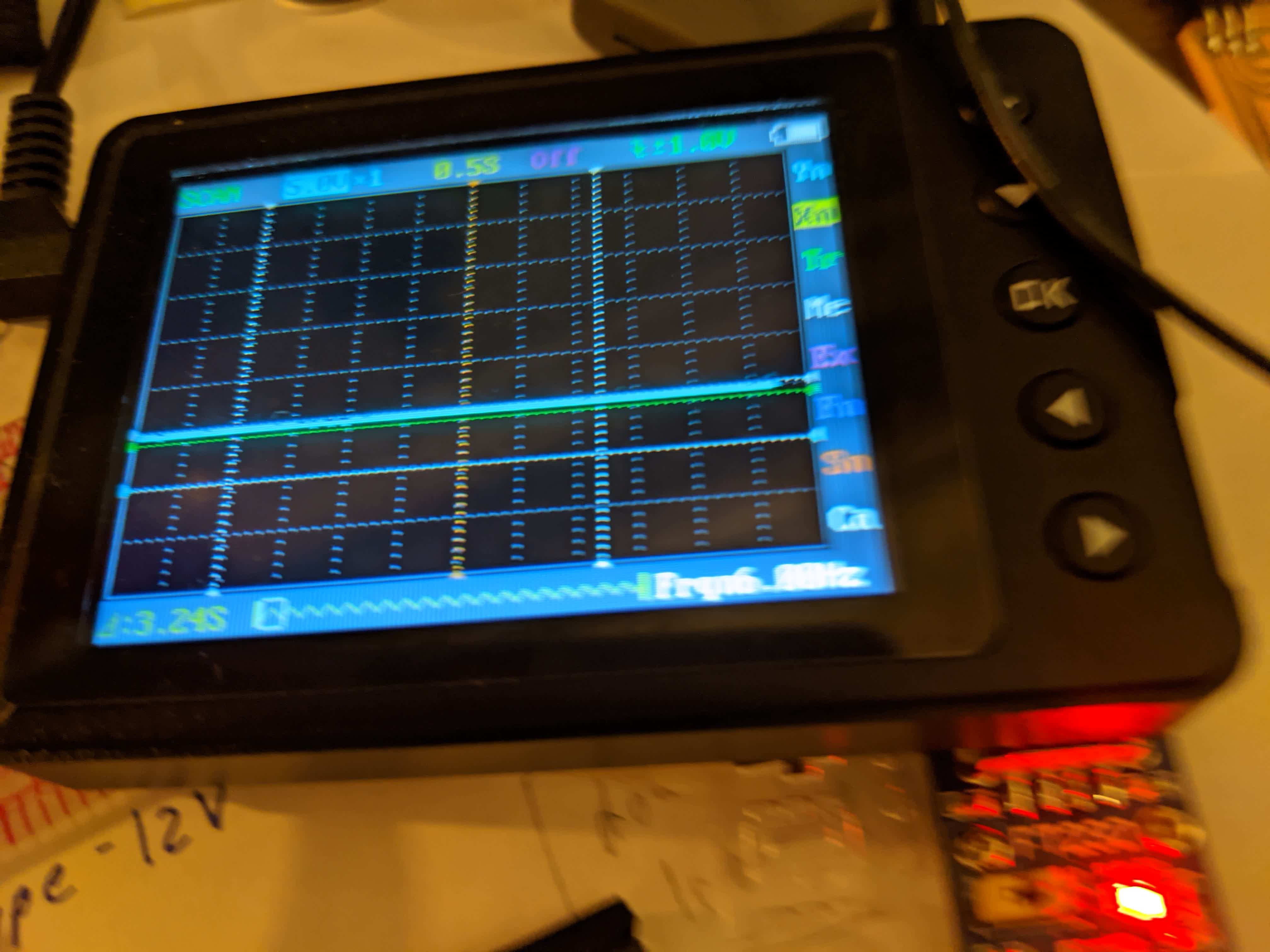
It's just flat line. Here is the signal when I shine a flash light onto it:
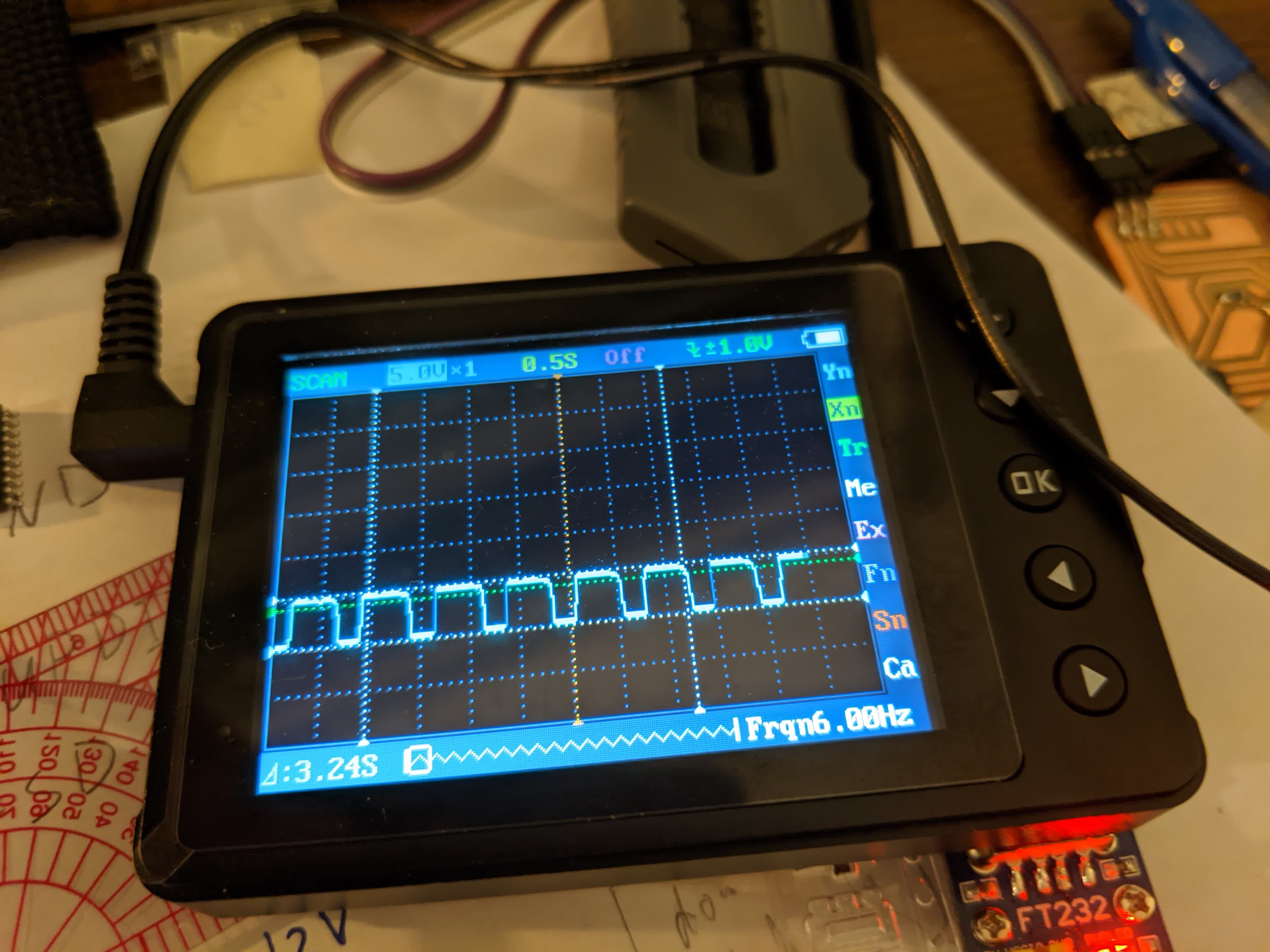
First thing to note is an amplitude of 5V between HIGH and LOW. Secondly, it looks like it is HIGH for about 0.5s and LOW for about 0.25s (~33% duty cycle). I don't really understand why it fluctuates between HIGH and LOW like this. I think it is because of PWM, even though I programmed it to do an
analogRead()
of the phototransistor, it seems like I am not getting a true analog read, but a PWM which averages out to the voltage value it is reading.
Here is a demontration showing the motor simply running without any input from the phototransistor.
As I said, the point of this board is to run the motor based on how bright it is. The sketch to do this can be viwed here. Here is a demonstration showing what happens in the dark when I flash a flashlight onto the board.
As you can see, the motor is initially not moving, but then moves once I flash the light onto the board. The only thing that is bothering me here is that stuttering motion in the motor. I know that the motor is fine, we saw it running smoothly in the previous video. The only explanation I can think of is the HIGH/LOW readings from the phototransistor making the motor run and stop successively.
Additionally, I observed that even in a well lit room, this is not enough to make the motor move. I could only get it to move when I used the flash light. This tells me that these phototransistors really require a lot of light to be useful.
Though not the result I expected, this is a board that controls a motor to go based on how bright it is. I don't think I'll be using the phototransistor in my final project though.
Time of Flight Board
I'll be honest, I got really excited about the VL53L1X time of flight sensor when the Neil presented it in class. I've been struggling to find a decent long range sensory that would work for my stroller. The phototransistors seemed like they would require a large concentrated light to function properly. The IR proximity sensor only had a maximum range of 80 cm. Of course I considered ultrasonic sensors, but was worried about sound bouncing off and confusing the sensor from a 1m distance. The VL53L1X seemed like a godsend, with 4m of range and pretty accurate results (only a few mm off at that distance). In addition, the biggest challenge with using this sensor is soldering it, which Pololu graciously took care of by selling it mounted on a carrier board which is much easier to work with.I bought 3 of these from here. Pololu offers really good documentation on how to use the sensor here. I also went through the datasheet to learn some useful information:
-the sensor has a long distance mode with a range of 3600 mm in the dark and 730 mm in strong ambient light. For medium distance the ranges are 2900 mm and 760 mm, and for short distances the ranges are 1360 mm and 13500 mm for dark and light ambient conditions.
-a minimum time budget of 140ms is required to reach the maximum distance of 4m (in the dark on a white target).
-the XSHUT pin is optional and used to power on/off the sensor and is useful for when using multiple sensors to set addresses for each.
-the full field of view of the sensor is 27 degrees, but a region of interest can be specified (I won't be doing so).
-they define what they mean by dark ambient conditions (basically no IR light), and provide the numbers for direct and indirect sunlight coming through a window.
-the sensor is most accurate when hitting a white target, and least accurate when hitting a dark target.
There is a lot more information in the datasheet. Overall, this seemed like a very promising sensor.
On top of the high range, accuracy, and ease of use of the carrier board, I found out that there is even an Arduino library for this sensor. There are very useful functions and variables here that make communicating with the sensor so much easier.
Due to all the above, I was very much excited about using this sensor and testing it out for my final project.
Doing so, unfortunately took me a few iterations. I'll begin explaining what I did and why it did not work below.
Design 1:
The first thing I did was make a custom part for the VL53L1X carrier board in Eagle. It is shown here: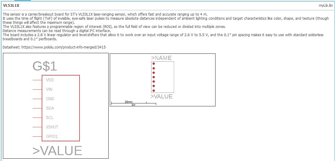
I initially started by designing around the ATtiny412, thinking this would be more than enough to handle this one sensor. Here is a schematic of my board:
and here is the layout:
After going through that, and cutting the board and soldering the components, I realized I made a grave mistake. Here is the 412 schematic:
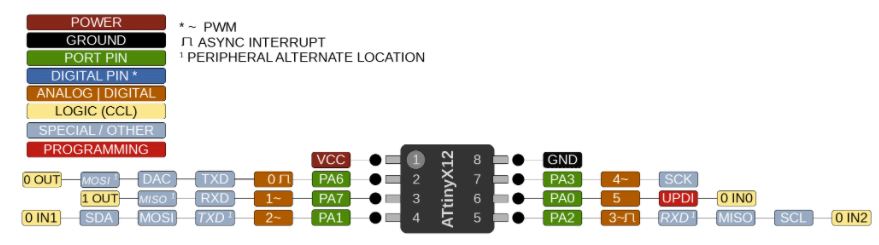
I had never worked with an I2C device before, and did not realize the importance of SDA (data) and SCL (clock). It turns out that the VL53L1X is an I2C device that needs to connect with SDA and SCL. The ATtiny 412 SDA pin is on pin4, and the SCL pin is on pin 5. I had these two swapped. In addition, I learned that I needed to include pull up resistors on the SDA and SCL lines, which I did not do. I don't think it is absolutely necessarey (Neil shows an example without pullup resistors), but it is recommended. So I scrapped this board and started over. Note, I desoldered all the components and recycled whatever was not damaged...trying not to be wasteful here.
Design 2:
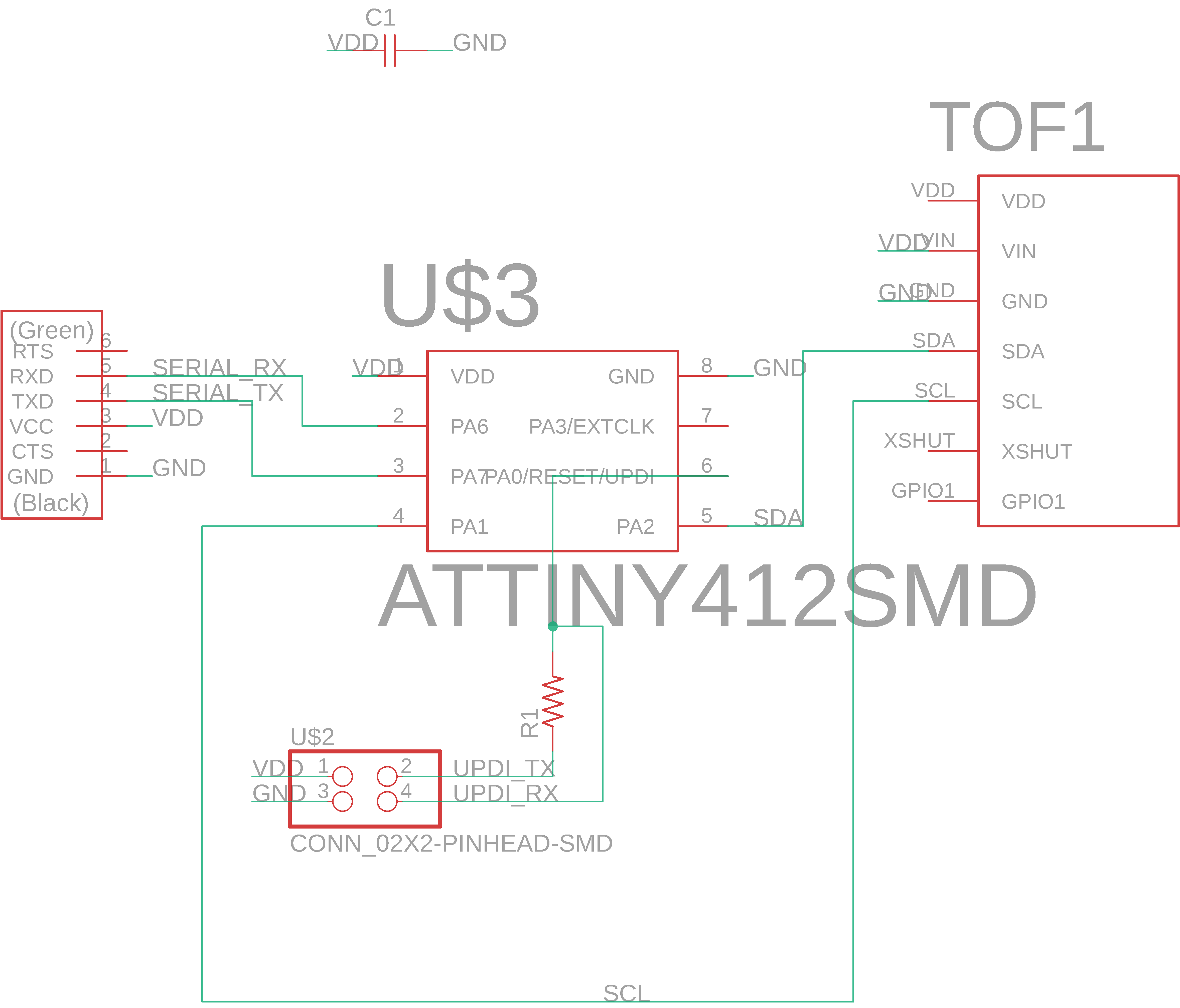
I went back to the drawing board and remade my board. Here is the new schematic: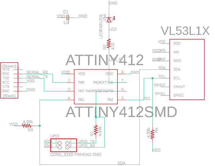
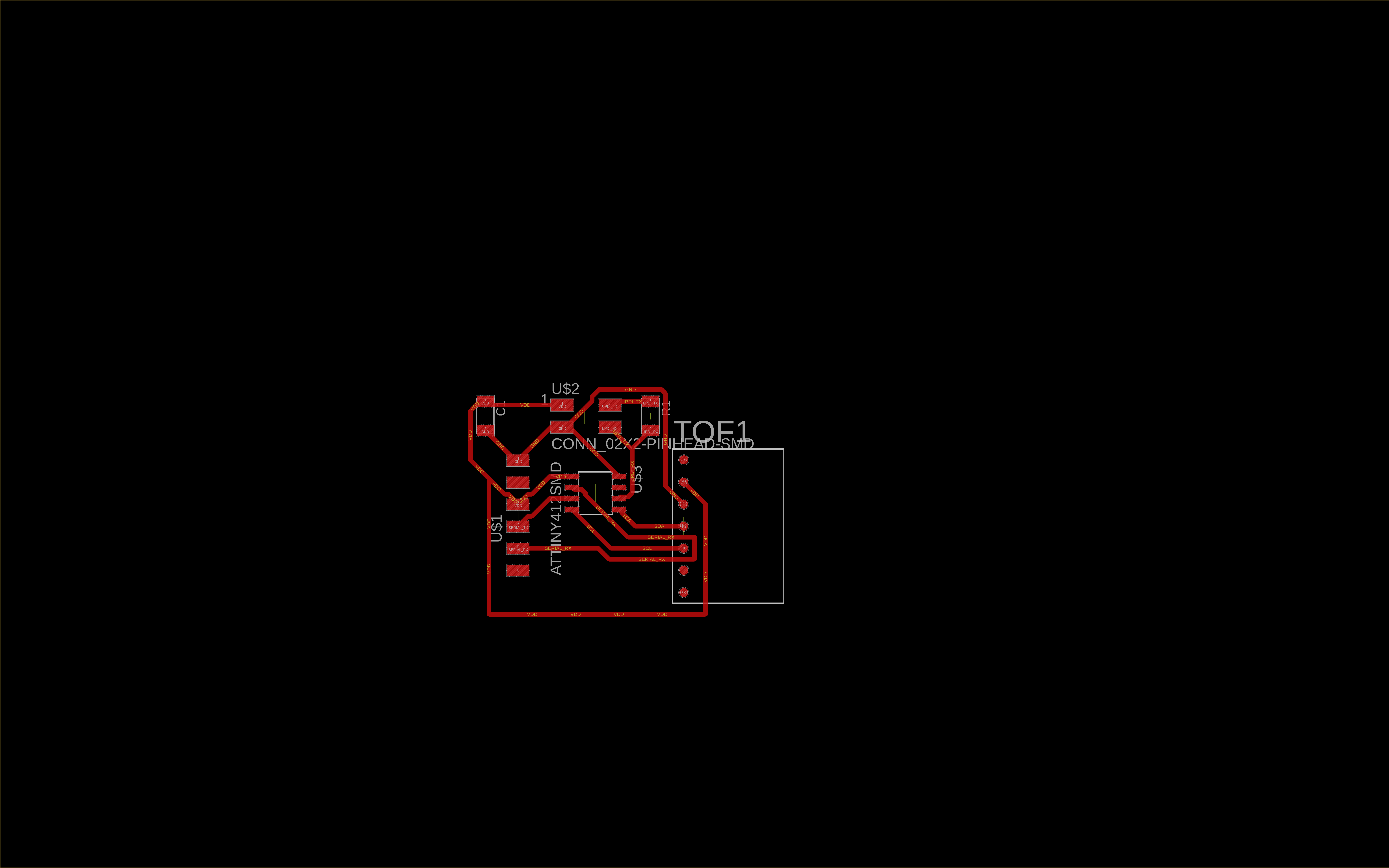
and here is the new layout:
You can see this revised version has pull up resistors (5k) on both the SDA and SCL traces. I also properly placed the SDA line from the VL53L1X to pin 4, and SCL to pin 5. Here is the resulting board:
I was really excited to try this after redoing it. I used the example code provided with the VL53L1X library, and tried to upload...only to run into another problem...
Not enough memory to upload program onto ATtiny412...overflowed by 4125 bytes...so close yet so far away...
This really frustrated me. Little did I know that the ATtiny412 has a memory of 4KB. The 4 in 412 turns out to stand for 4KB. The program I was trying to upload was 4.125 KB. It was apparently a hefty sized program due to including the
Wire.h library and the VL53L1X library.I guess I should have spent more time reading the microprocessor datasheet and checking the program size before making the board.
Before scrapping this board, I went through the data sheet really quickly and learned that for the AT chips:
-the "tiny" means that the microprocessor can have up to 20 pins
-the first number is the Flash size in KB: 4 in 412 is 4KB, the 16 in 1614 is 16KB, the 32 in 3216 is 32KB
-the 1 in 412 indicates that it is a 1-series chip, ie has UPDI capabilities. The same for the second 1 in 1614 and the first 1 in 3216
-the 2 in 412 is the pin designation for 8 pins. The 4 at the end of 1614 means 14 pins, and the 6 at the end of 3216 means 20 pins.
After learning all this, It was back to the drawing board...again
Design 3:
I was redoing this for hopefully the last time. I know that the program I am uploading is slightly over 4KB, so I decided to go with the ATtiny1614 this time. Once again, here is my schematic with pullup resistors in place and SDA connected to pin 8 and SCL connected to pin 9 (triple checked this time):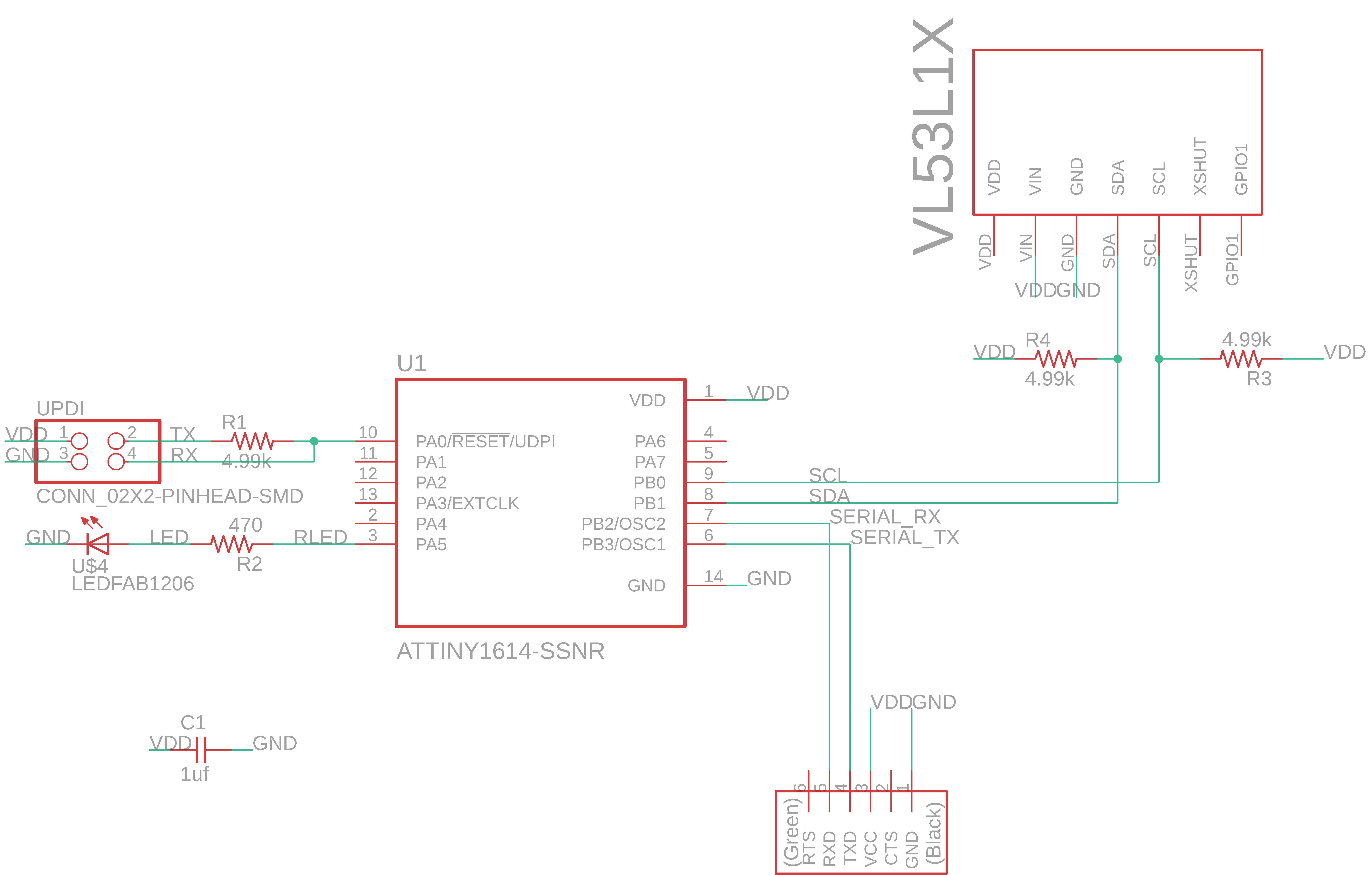
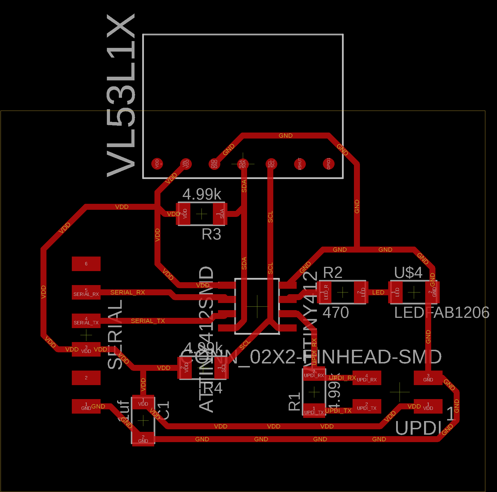
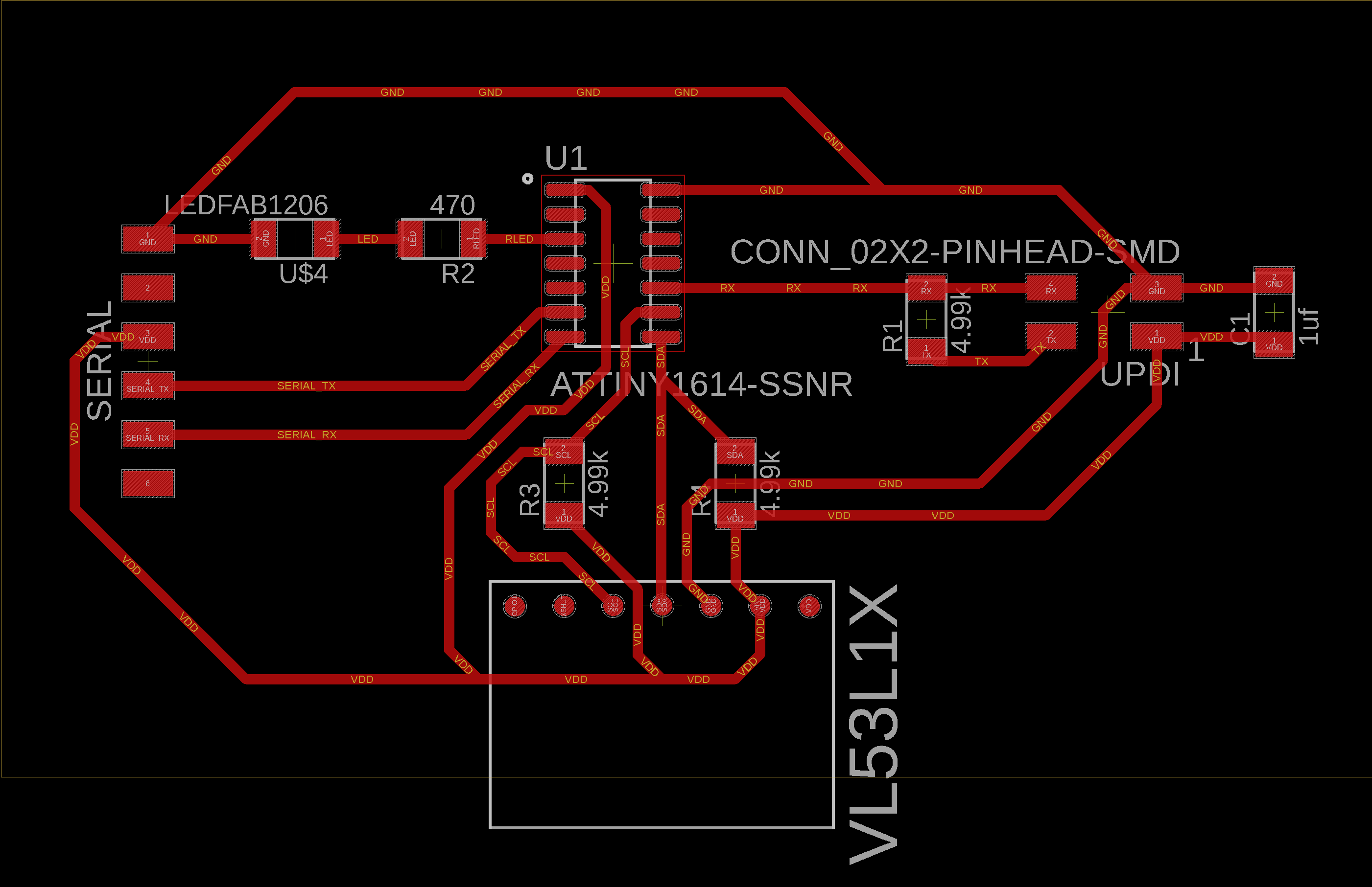
and here is the board layout:
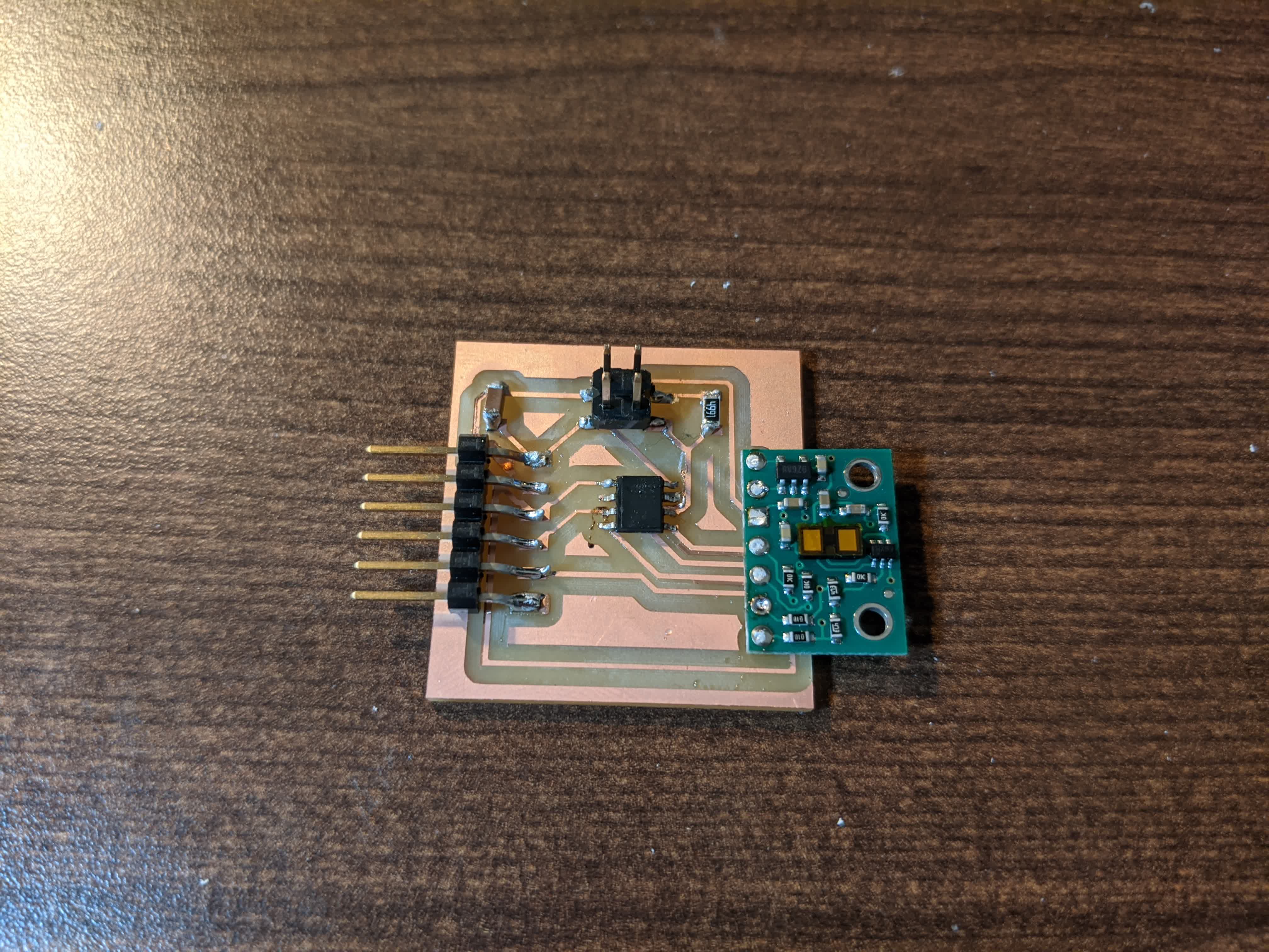
Here are all the components layed out for the final time:
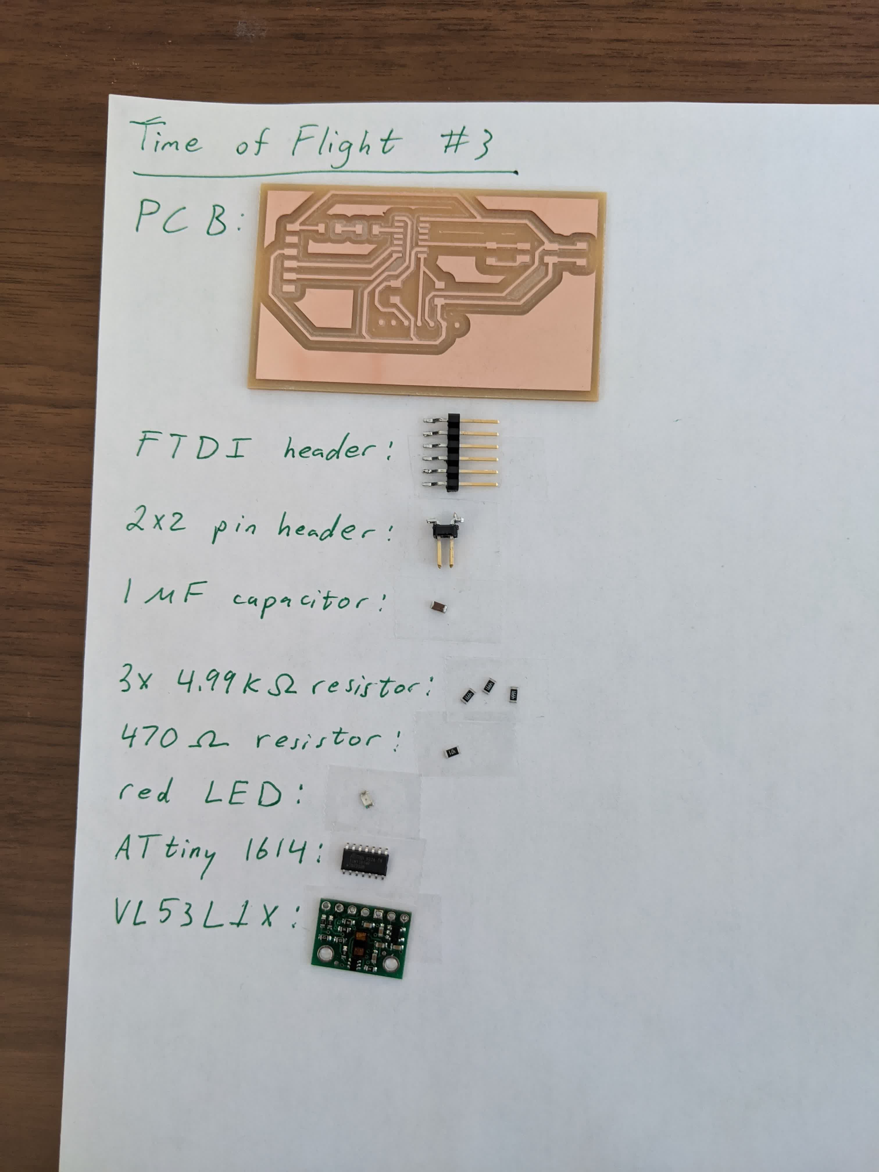
Here is my final time of flight board:
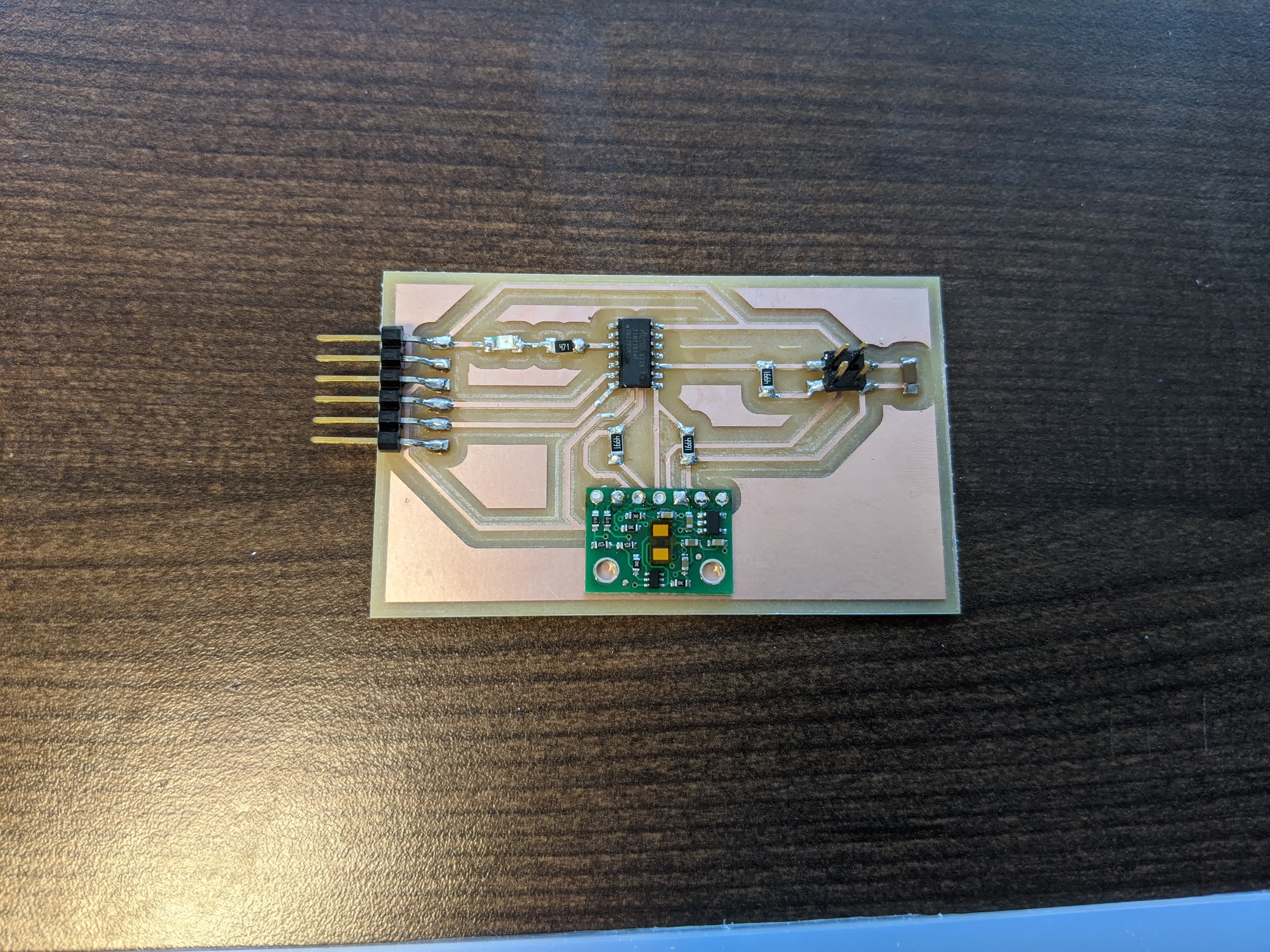
At this point I was elated and ready to test this thing out! I modified the example code provided by the manufacturer to turn on the LED on the board once it finishes going through the
void setup() function, just to reassure me that the program is uploaded successfully. The sketch can be viwed here. I used putty and logged some data shown here:
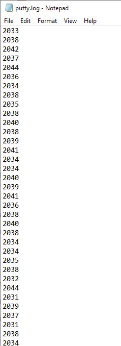
This is how far the top of my desk is from my ceiling. I measured this to be ~2m using my measuring tape, so this is good on accuracy! I also checked that it's actually reading distances properly using the Serial Monitor in the Arduino IDE, but I did not know how to record it and didn't figure out how because I ran out of time. I basically had my daughter hold the measuring tape against my table top next to the board, and pulled up with my hand sticking out as a flag. The readings were good!
It took me a while, but I got this sensor up and running and I am really excited about using this in my final project!!