Web Design, Version Control, and Final Project Brainstorm
Laser & Vinyl Cutting
3D Scanning and Printing
Make Something Big
Molding and Casting
Electronics Production
Electronics Design
Embedded Programming
Input Devices
Output Devices
Networking & Communications
Interface and Application Programming
Final Project
Group Assignment
The group assignment was to characterize the design rules for our PCB production process. This was done in collaboration with with Jordan, Maya, Gil, and Emma. The process and results can be viewed here.Electronics Production
Assignment: make an in-circuit programmer by milling and stuffing the PCB, test it, then optionally try other PCB processes.
So things are a bit of a mess. This week, we have the following objectives:
-Build Clank
-Cut out a test piece to characterize the machine
-Cut out an in-circuit programmer using Clank
-Stuff the PCB
-Program and Test the PCB
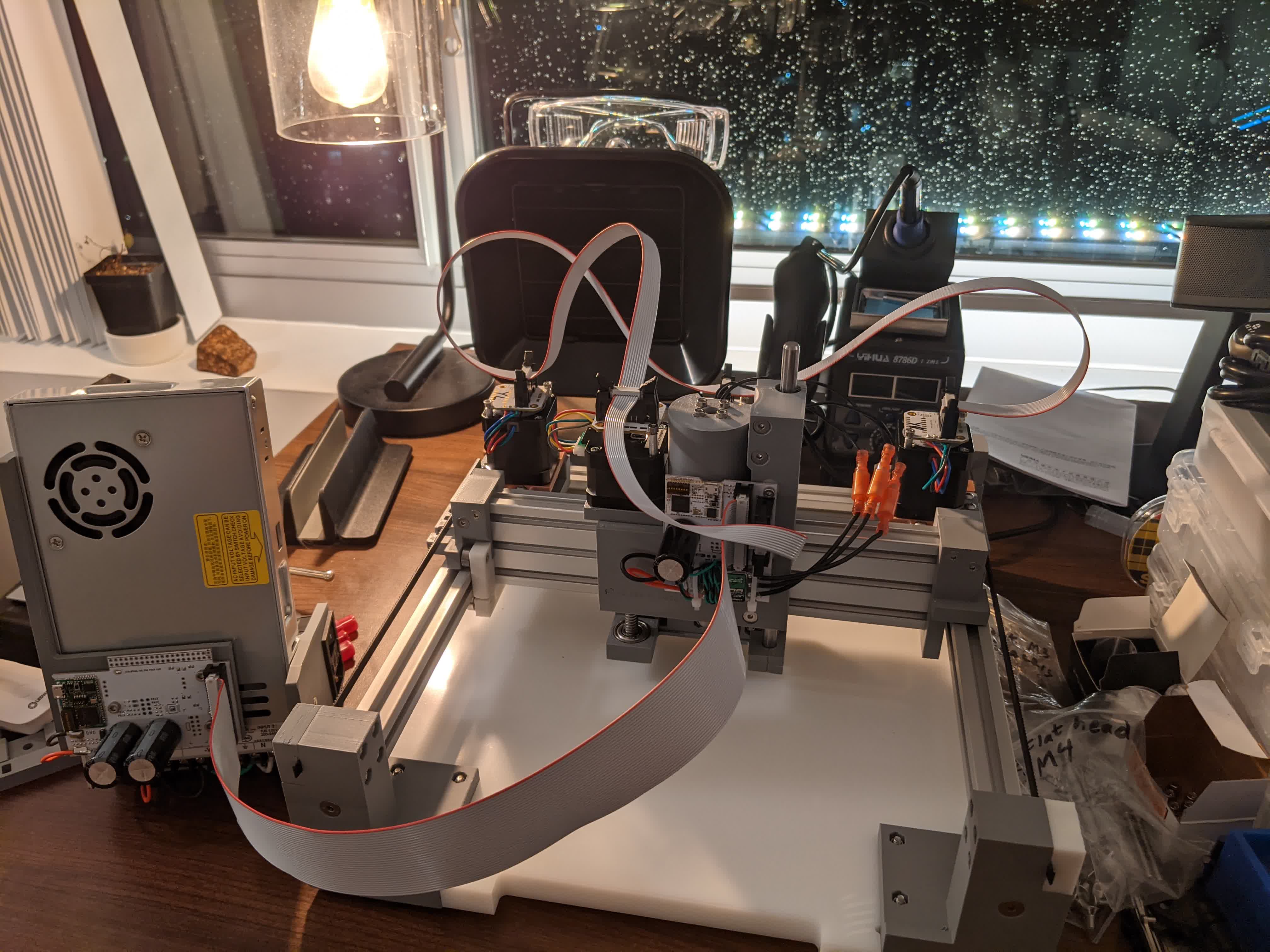
Build Clank
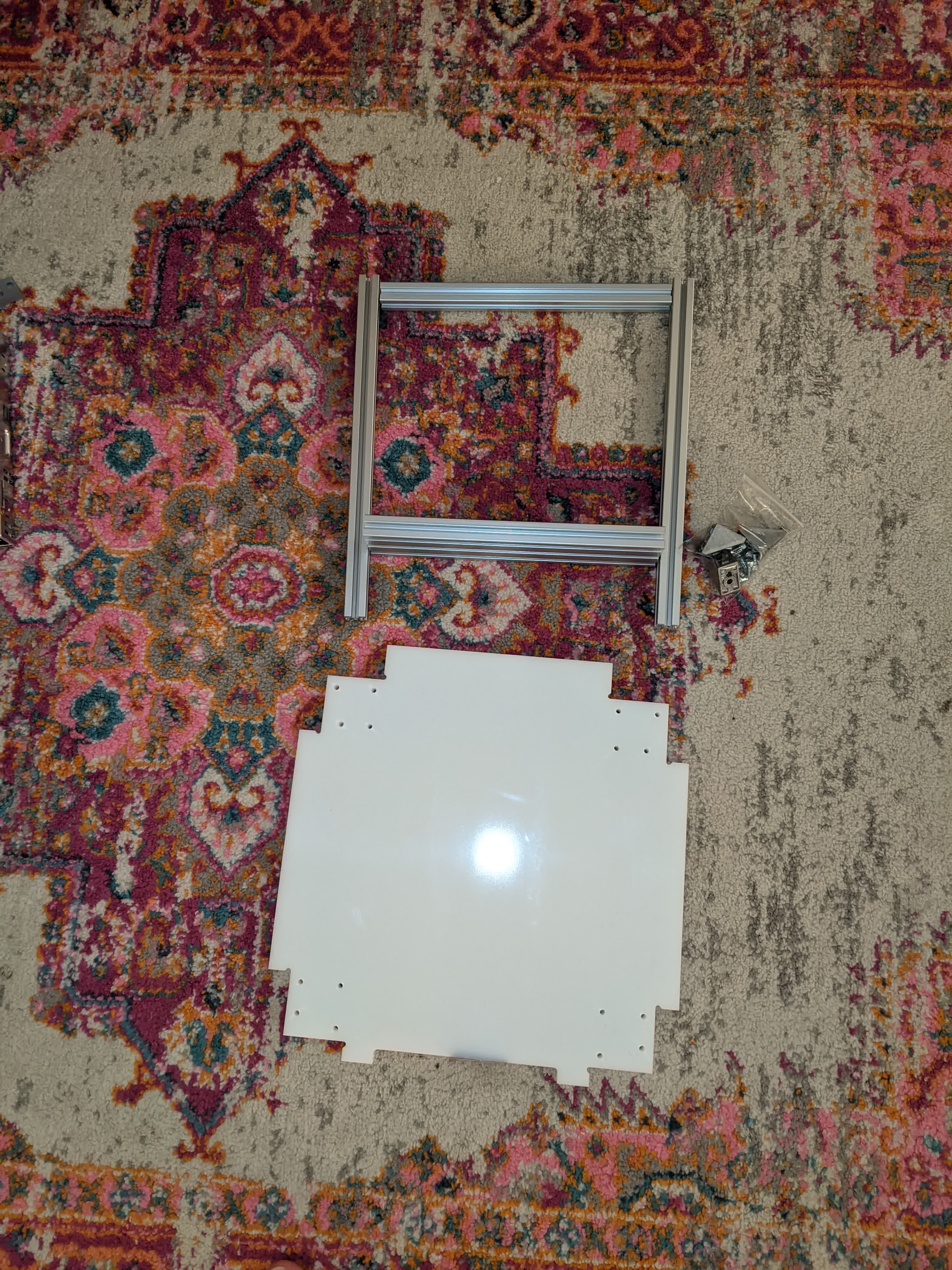
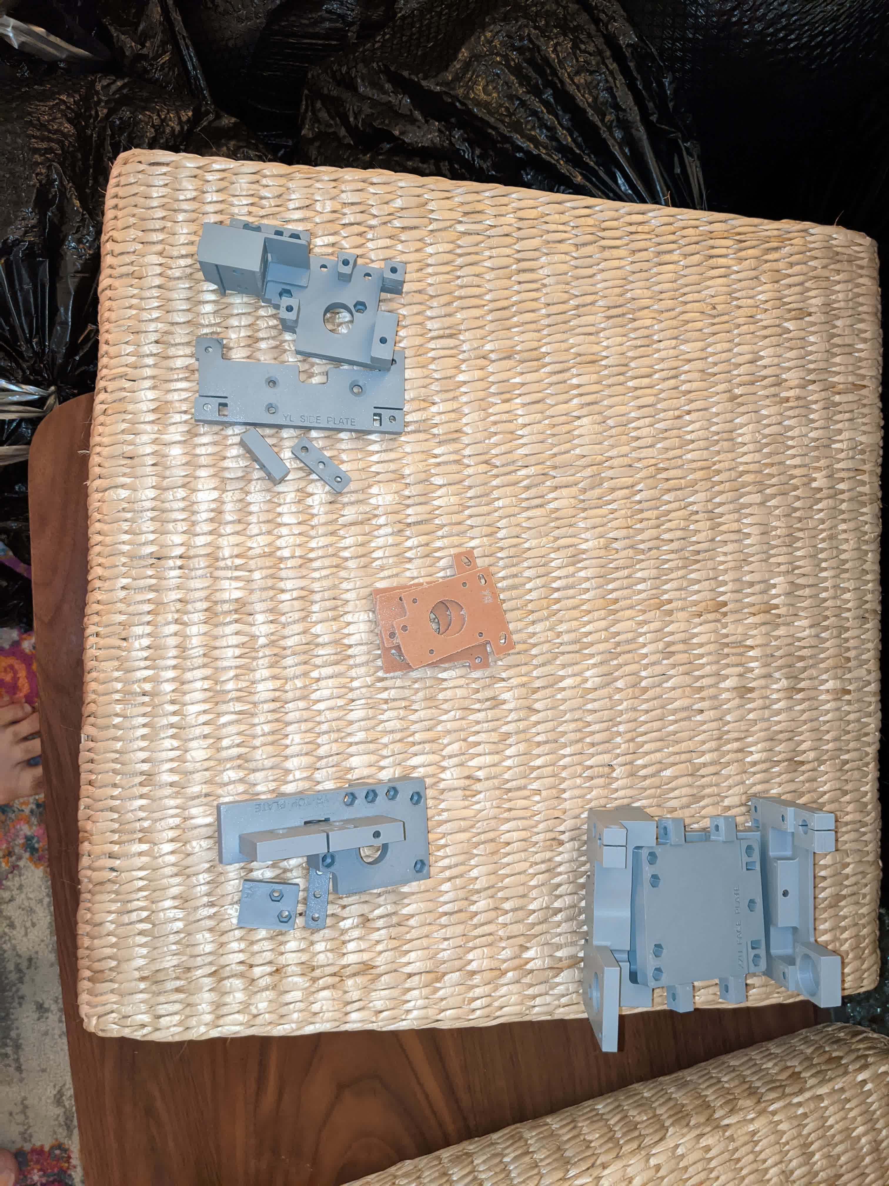
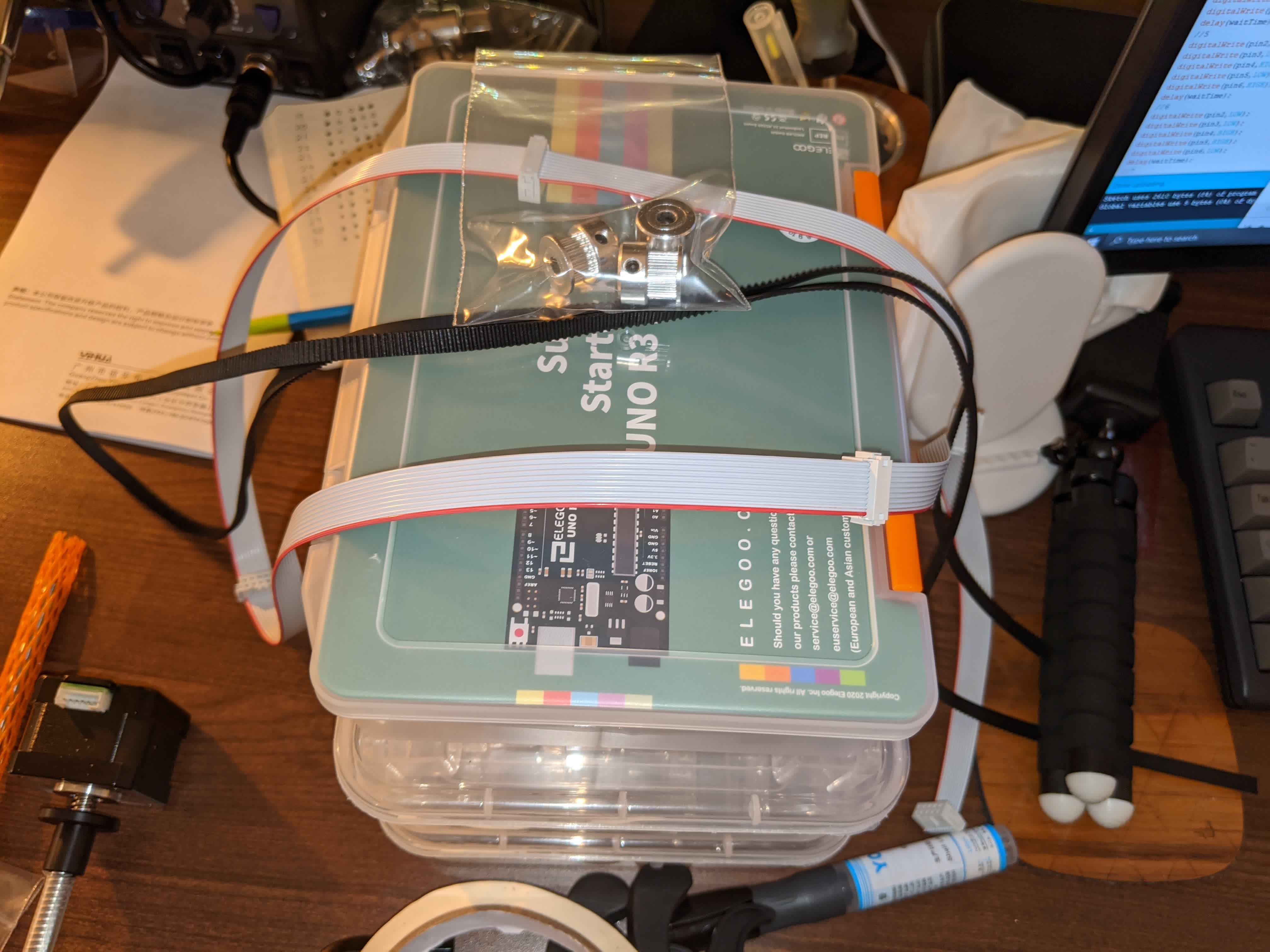
This was an extreme nightmare to do due to the many complications I faced. Jake's building tutorial was great. However, there were some issues along the way. I'm not going to go in great detail about what I did to build Clank since it was in the tutorial, but here are the steps.First thing I did was put out all the parts and got familiar with each part and what it was for. Then I grouped them accordingly to the best of my knowledge.
Here is the bed and frame:
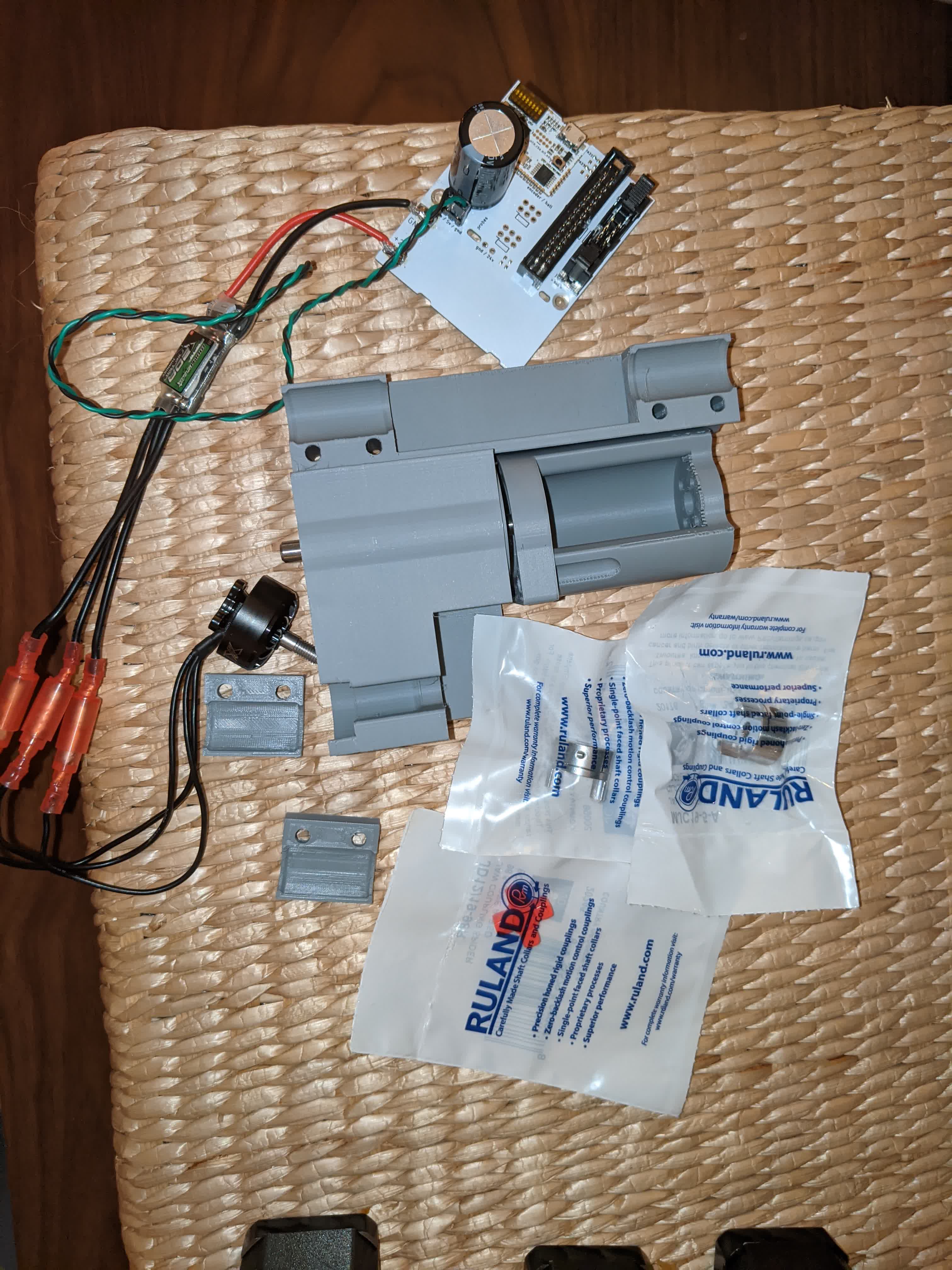
These are the parts associated with the power supply:

Spindle parts:
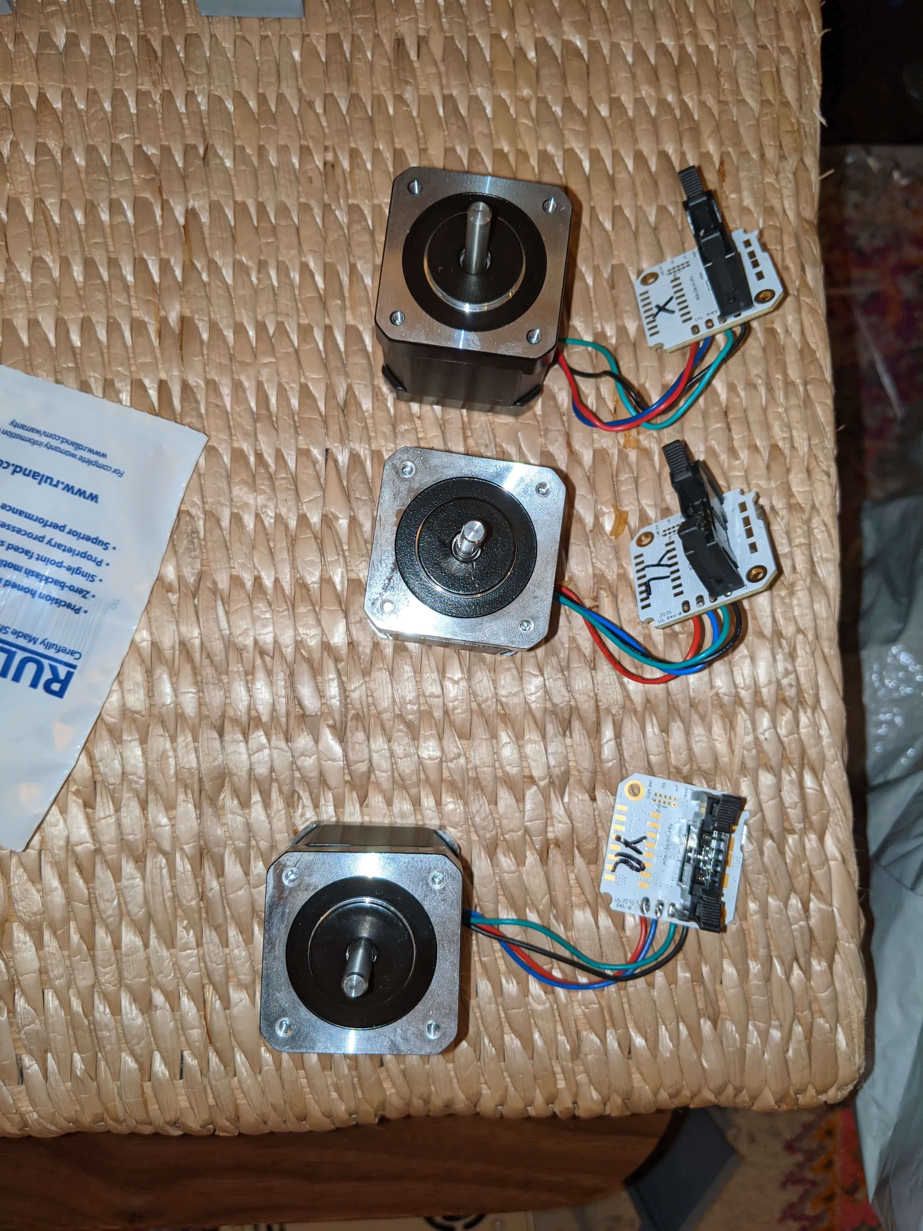
Motors to move in the x-y plane:
Corners that fit around the bed and frame:
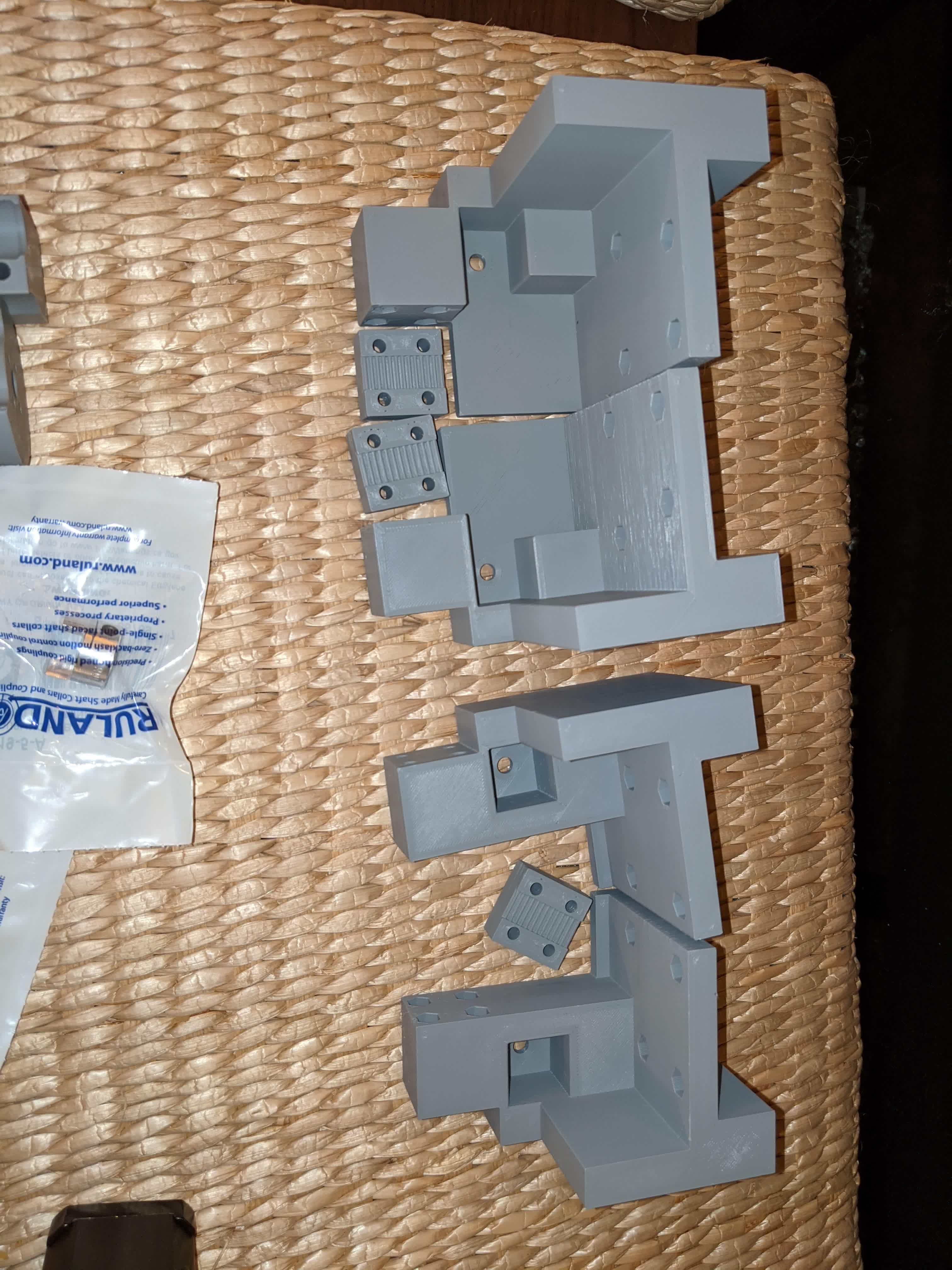
Carriages for the frame:
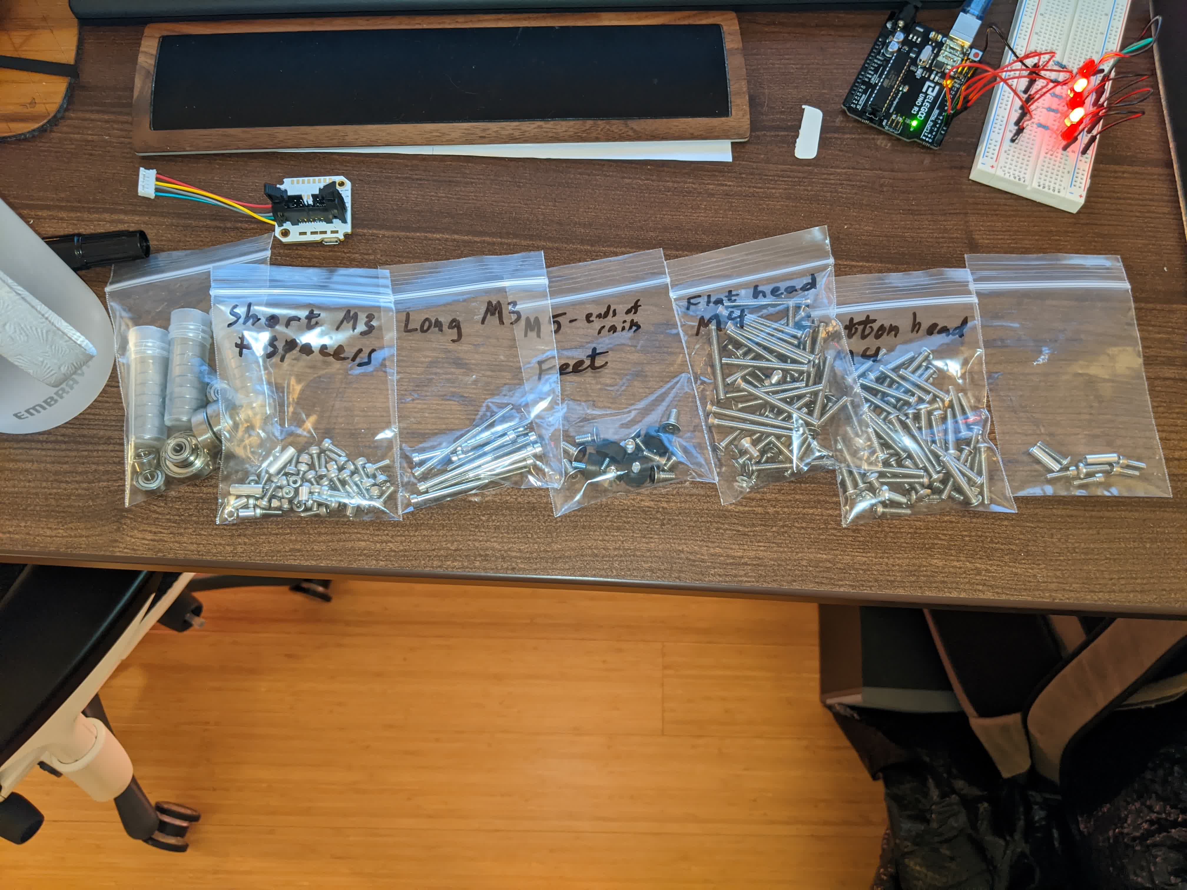
All the screws and hardware to fasten and hold everything together:
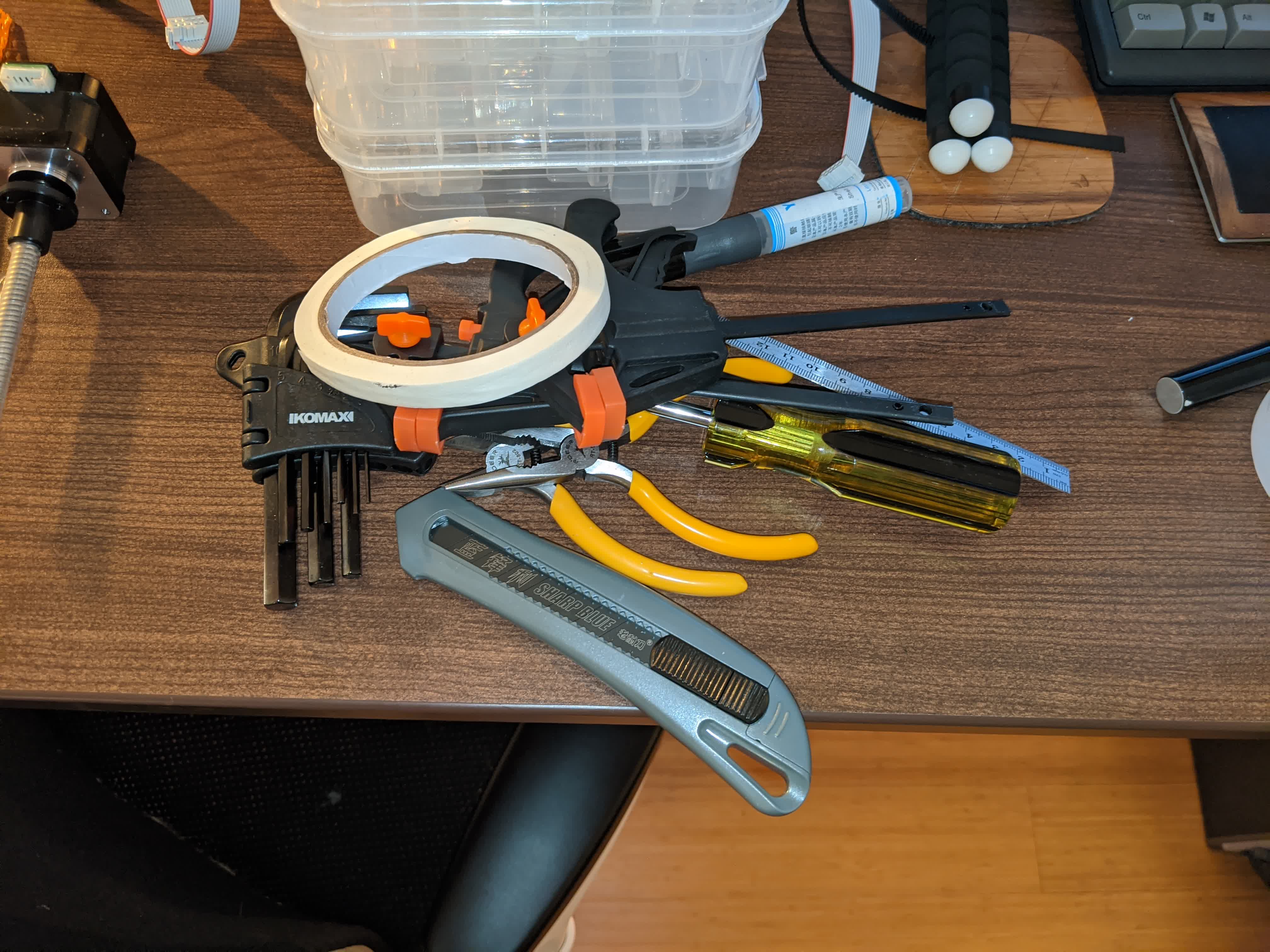
A bunch of tools to use like pliers and clamps:
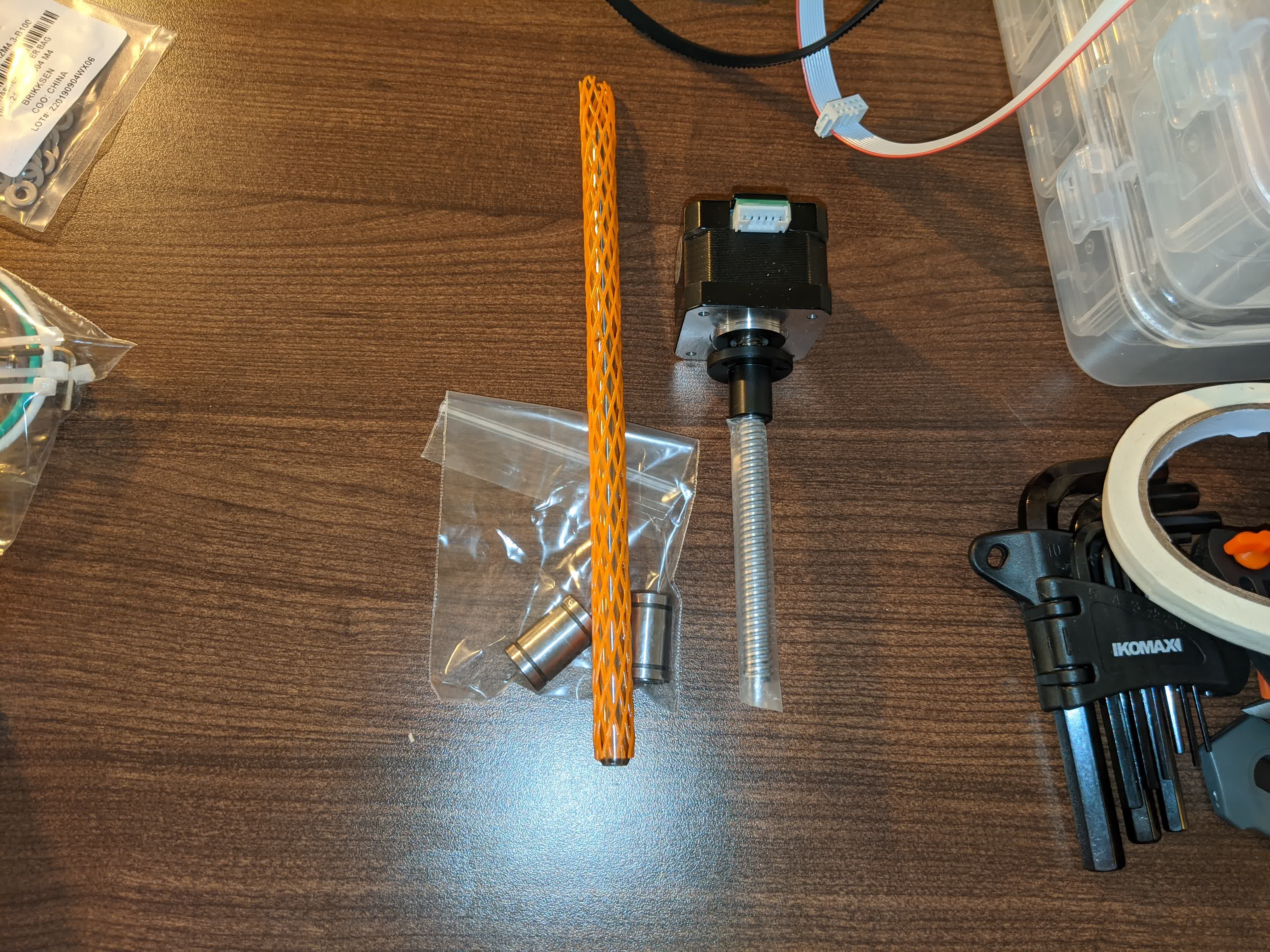
The z-axis motor and rod for vertical traversing:
The pulleys and belt and cable that connects all motors to the logic board:
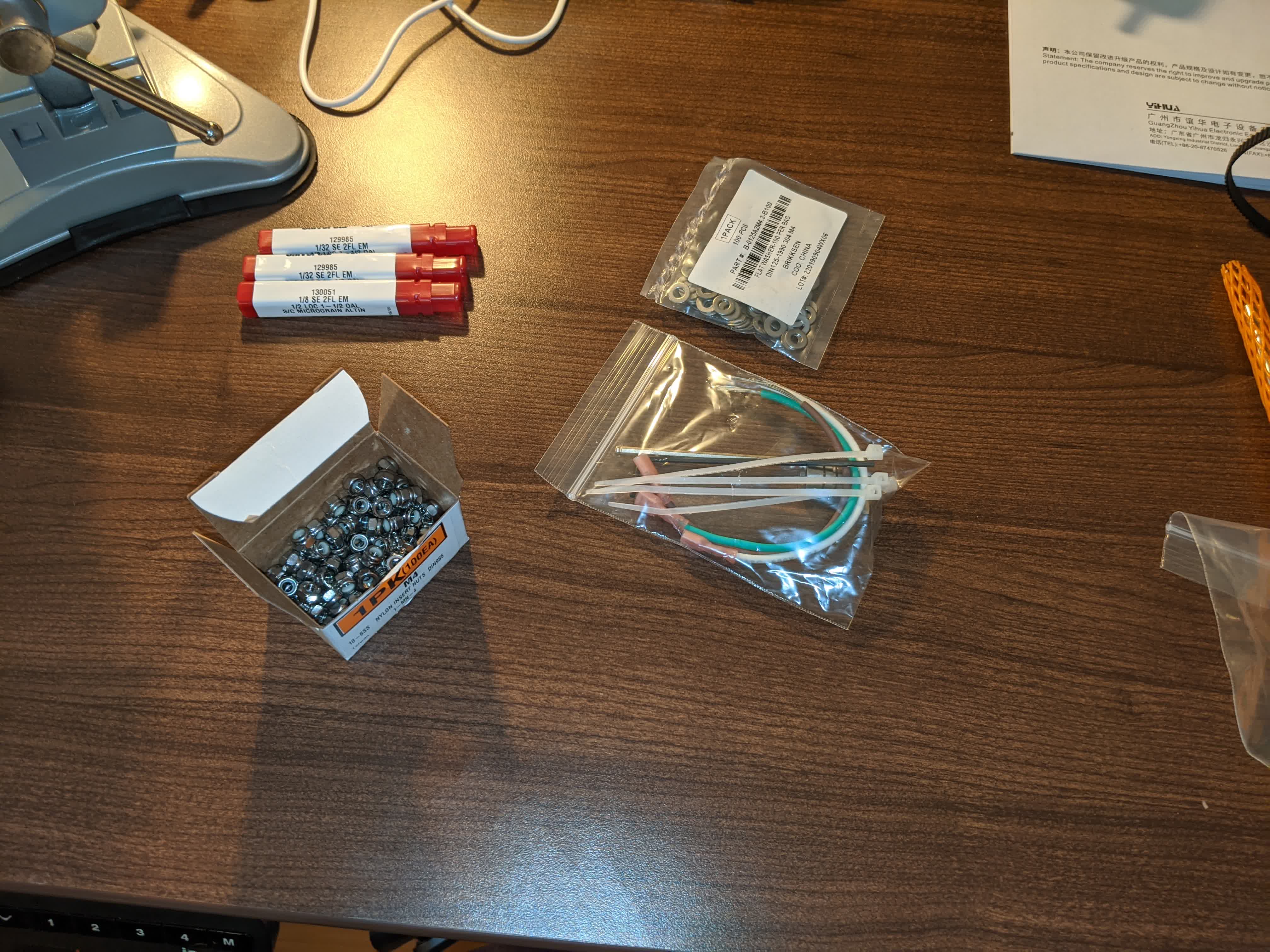
Nuts, washers, bits, etc:
Building
I started with the frame which went smoothly: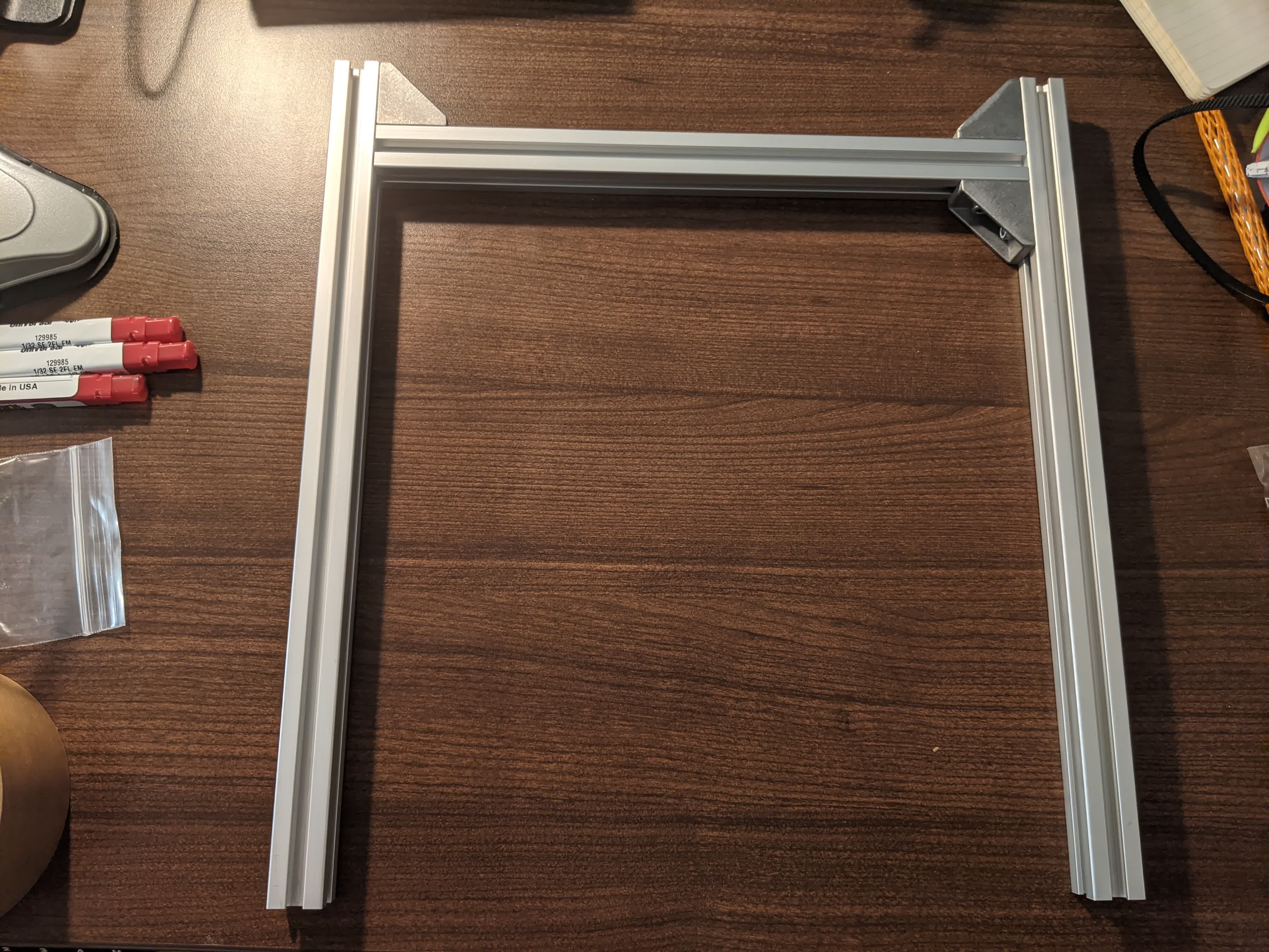
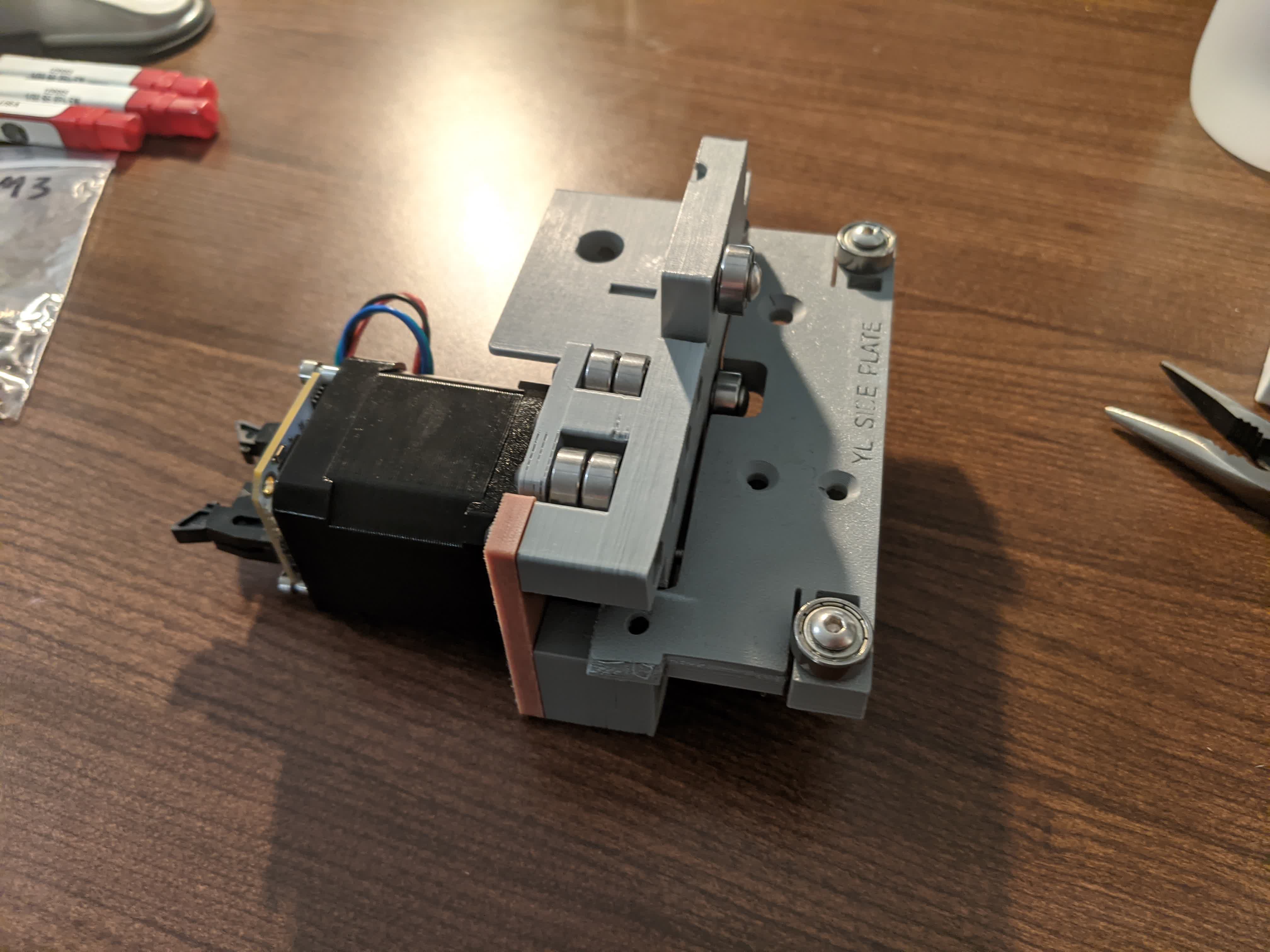
Then I started working on the Y left carriage and bumped into my first issue. The YL side plate was a bad print and I could not put a bearing where I was supposed to because neither nut nor screw could fit.
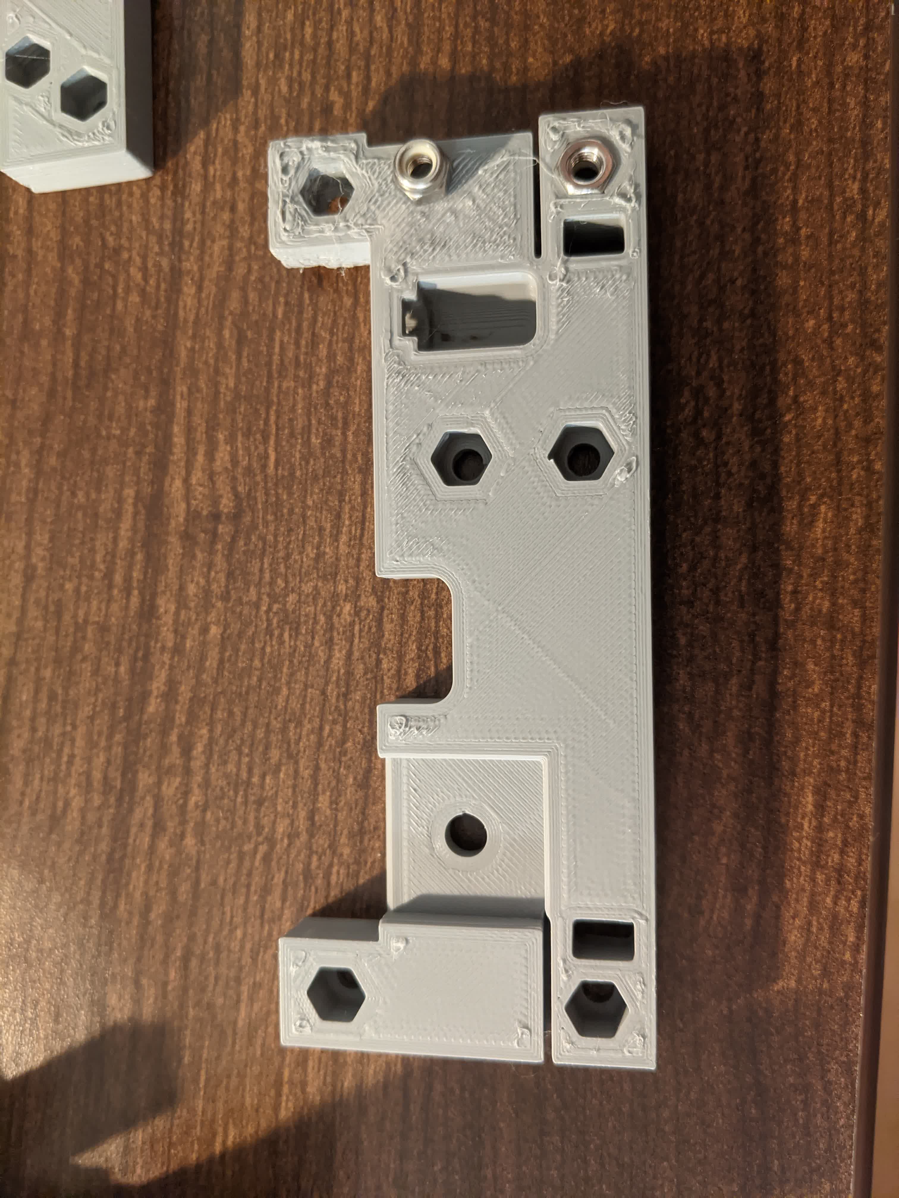
I proceeded anyways just to move on and tally up all the issues in one place, but this was number one. Here is the Y left carriage assembled and you can see that warped corner on the plate shown above.
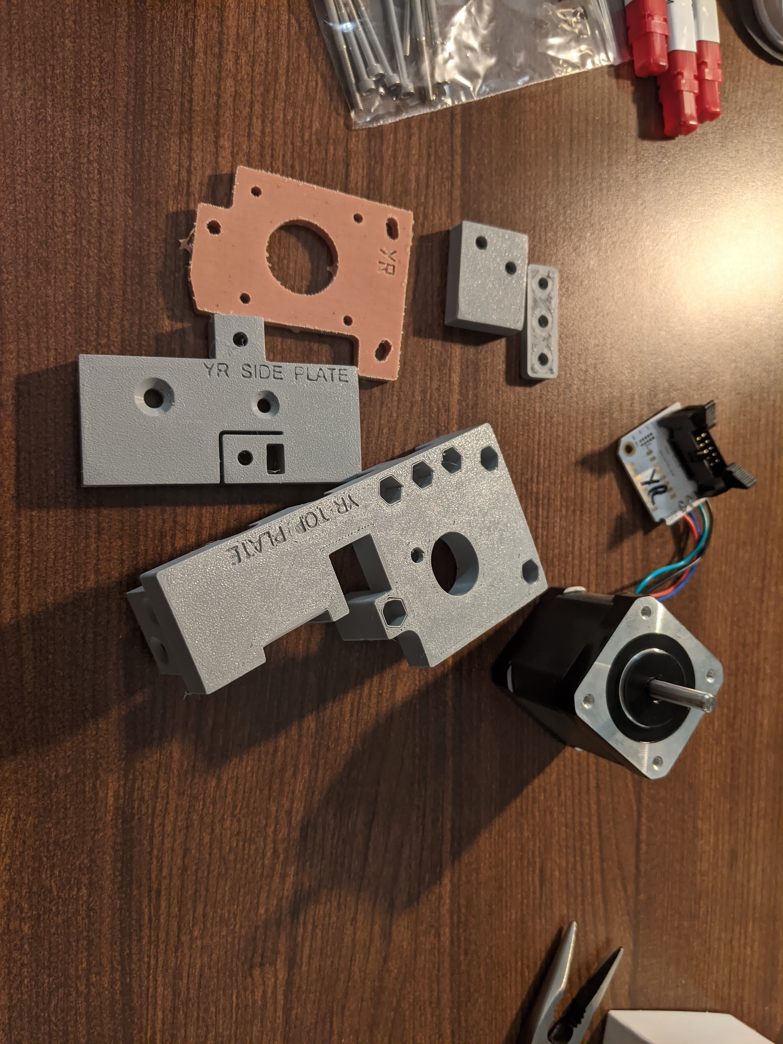
Next up, I grouped together the parts for the Y right carriage:
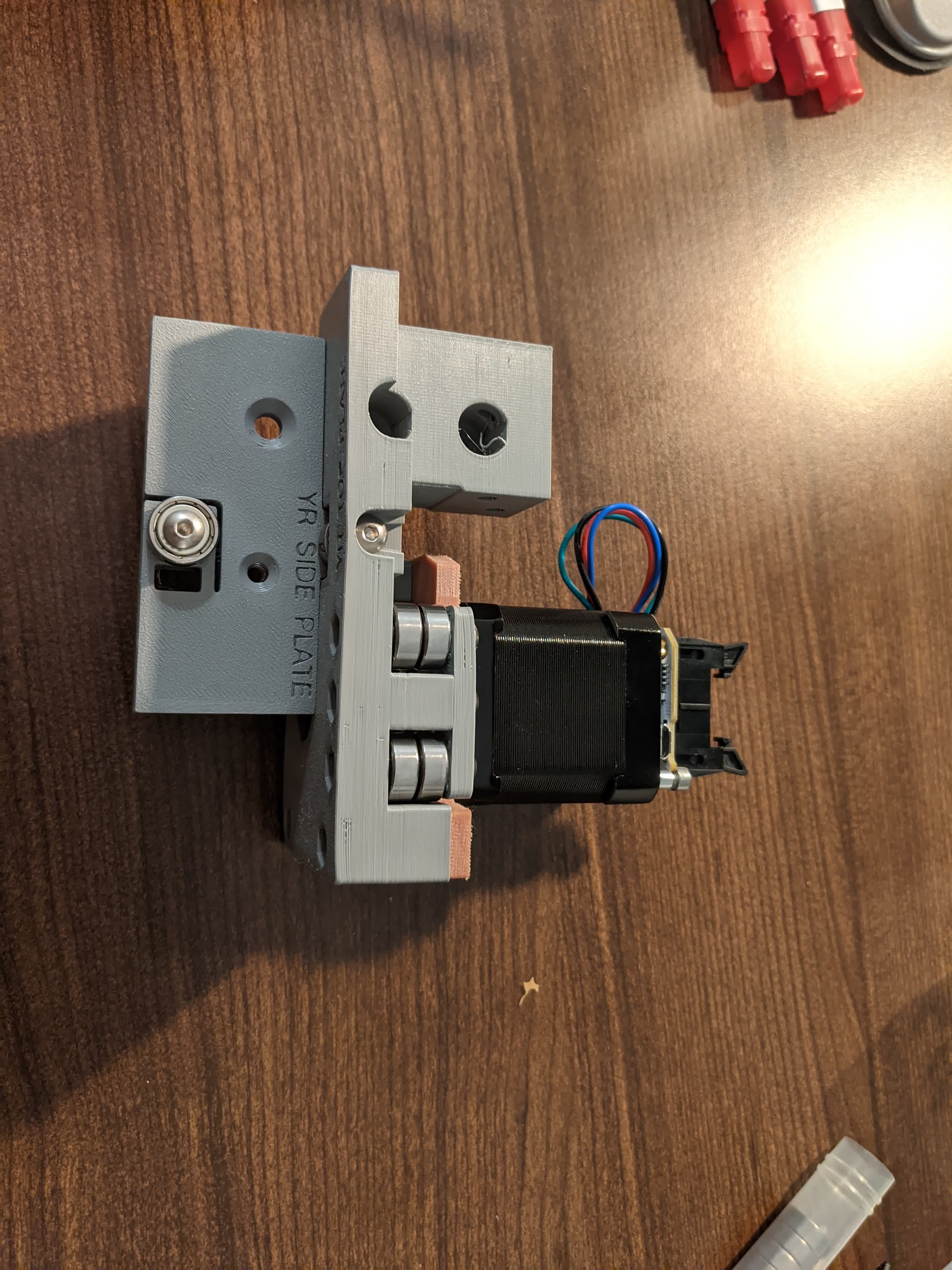
Here it is fully assembled:
Then I assemble the XZ carriage:
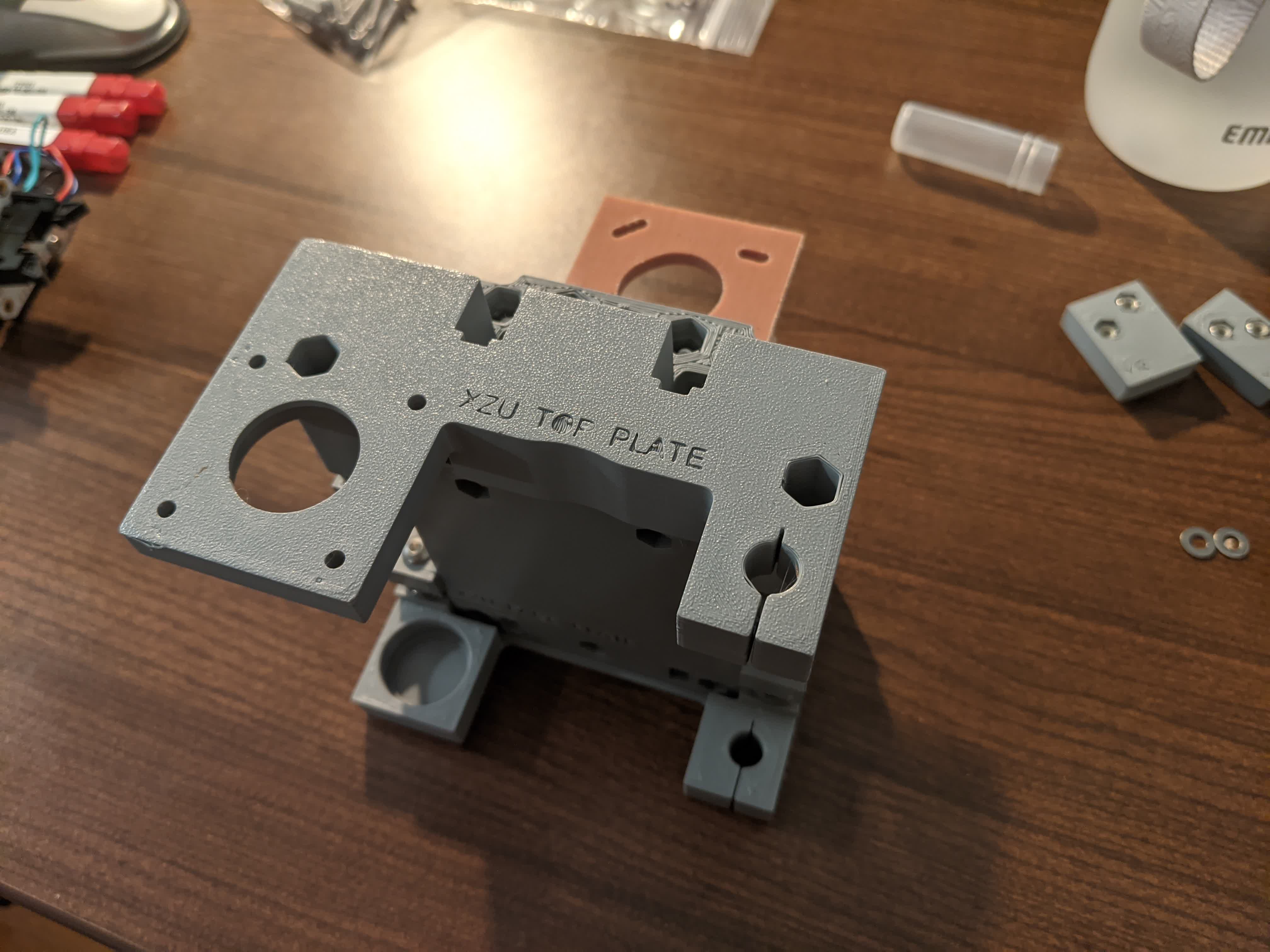
This part is supposed to move the bit in the x-direction, but also holds the spindle which rotates the bit as well as the Z motor to move the bit up and down. Here is where I had two additional problems.
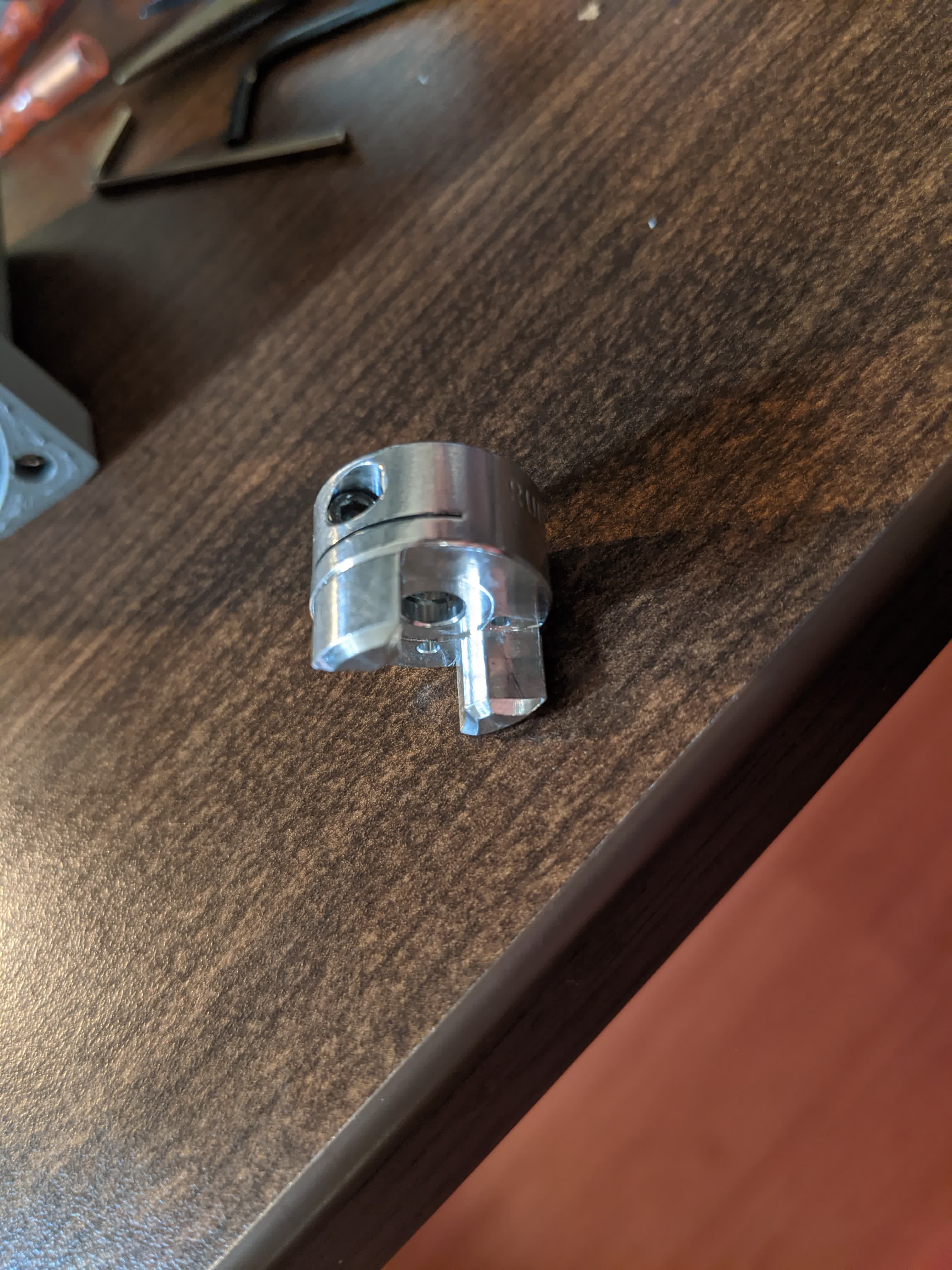
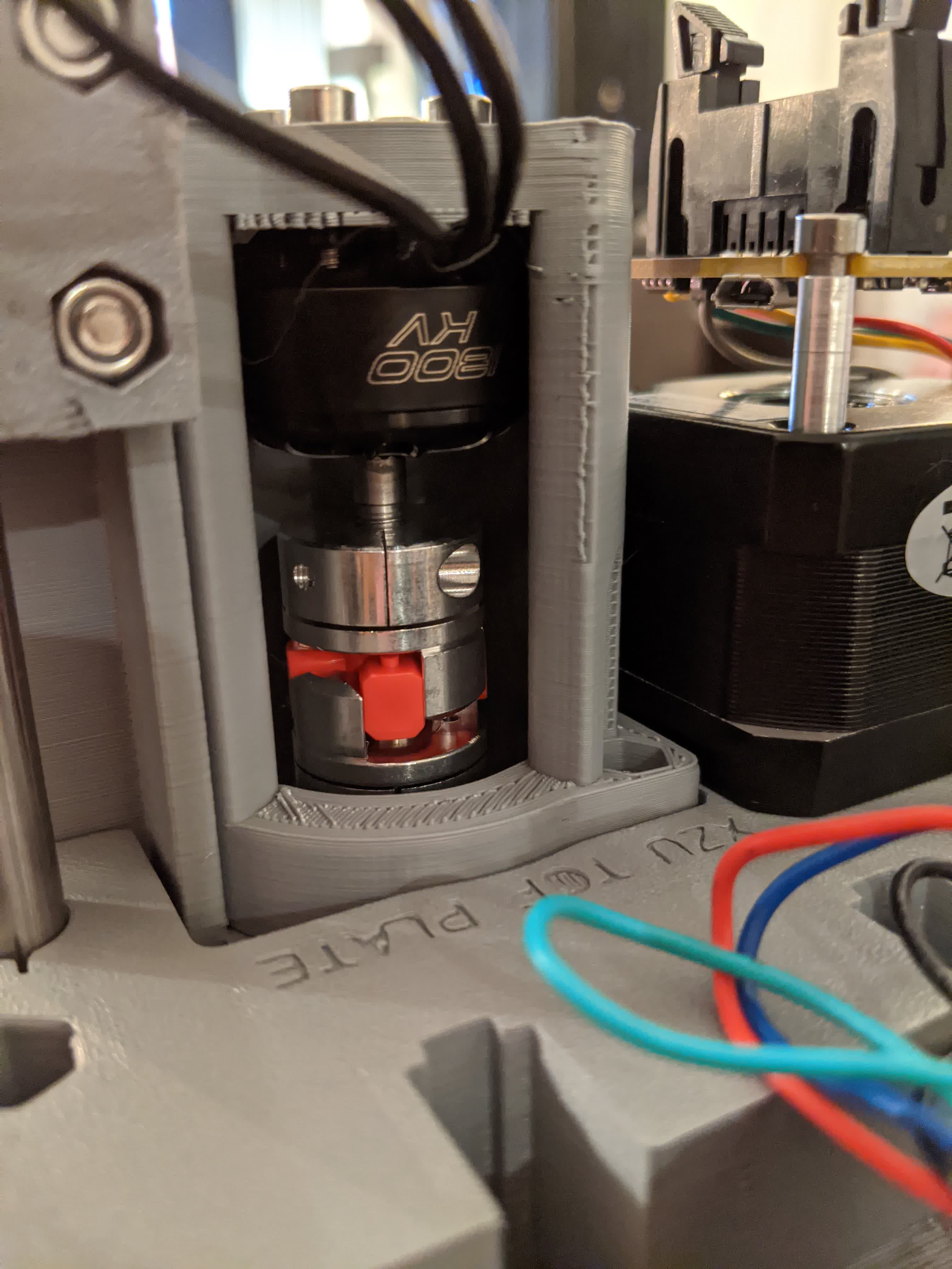
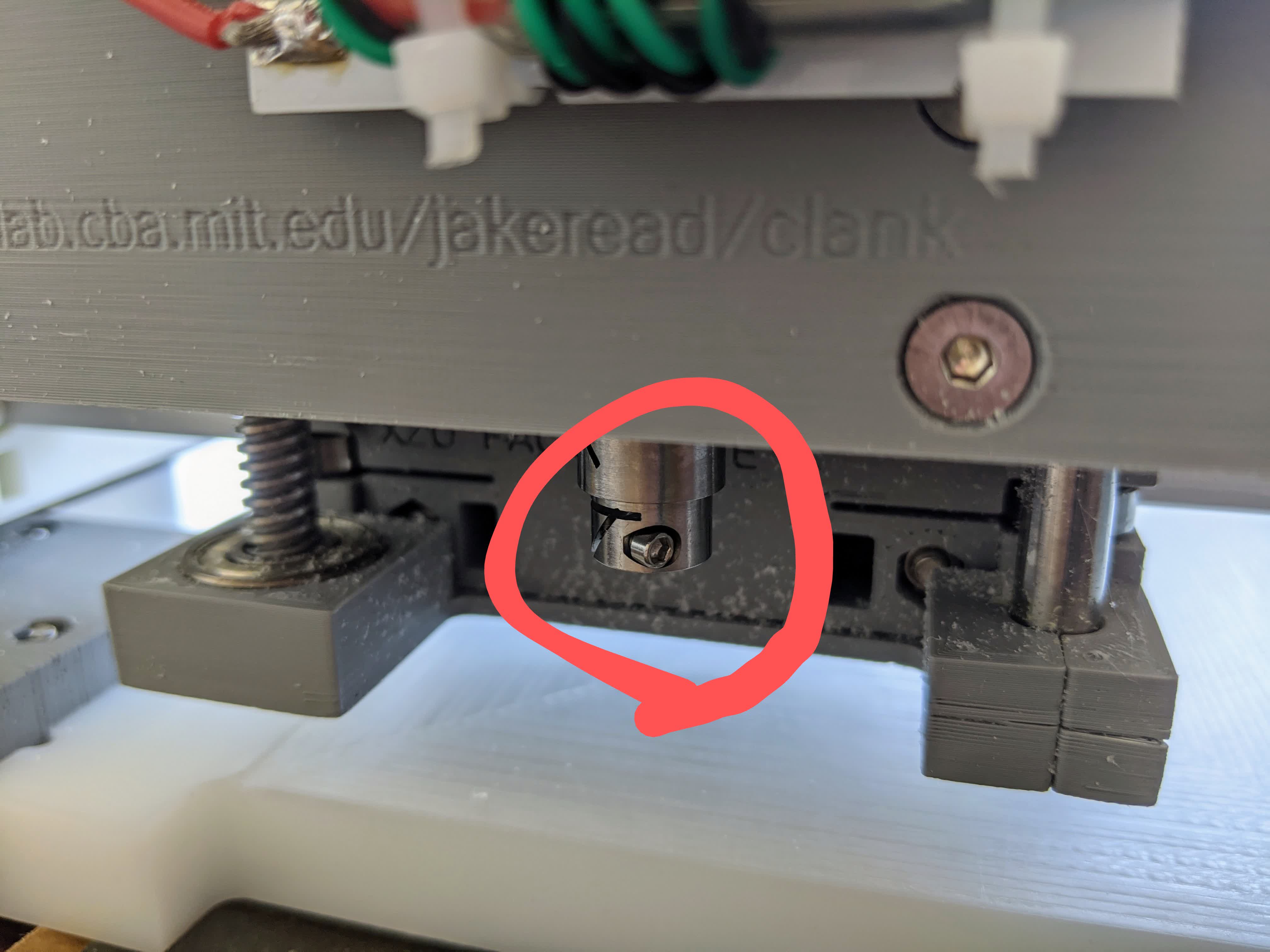
There is are two couplers that connects the spindle motor to the shaft that holds the bit. Alligning them just right was a bit of a challenge, particularly the one that fits on the spindle motor. While trying to tighten it on the threaded shaft of the spindle motor, I guess I over torqued and stripped the hex screw. This was problem number two. Here is the coupler with the stripped hex screw:
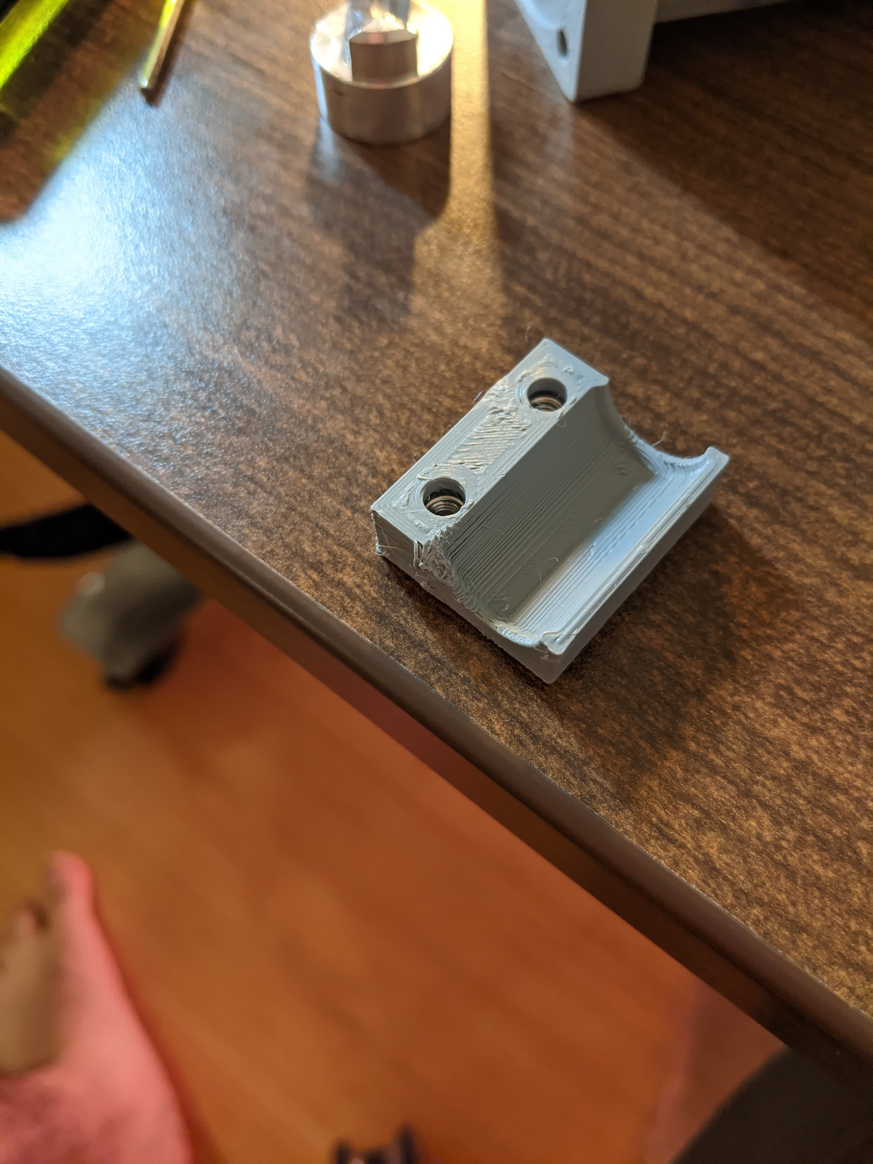
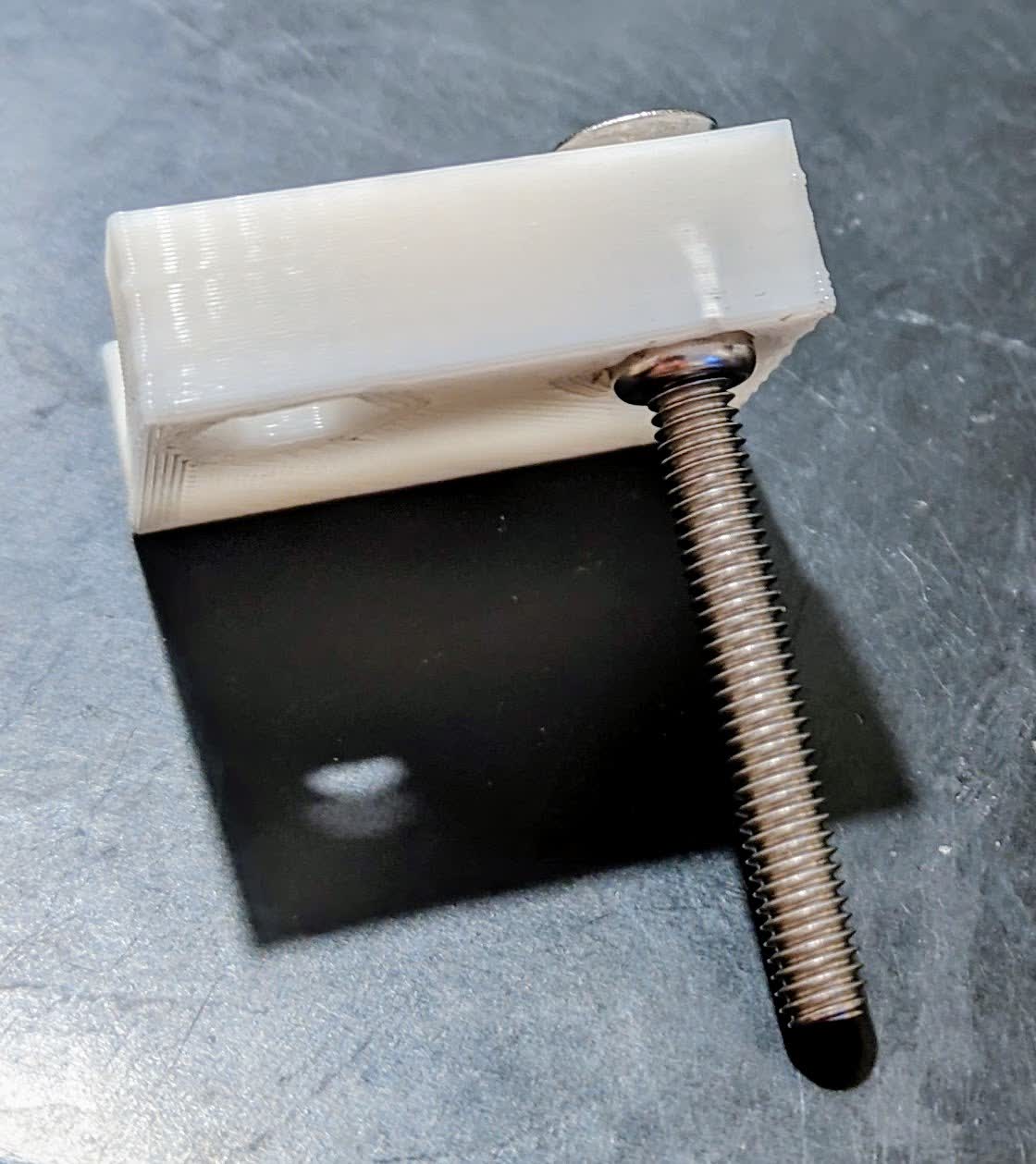
In addition, the third problem I had with MANY of these 3d printed parts was the tight tolerance between the nuts and the hex sockets they should fit in. I would frequently have to use a vice, or pliers, or my entire weight on the nut to push it in. This was struggle number three. I damages the linear bearing clamp that goes on the linear bearing over the rod on the XZ carriage:
After this, I discovered I had a missing belt clamp. We were supposed to have 4, I only had 3. This was problem number 4.
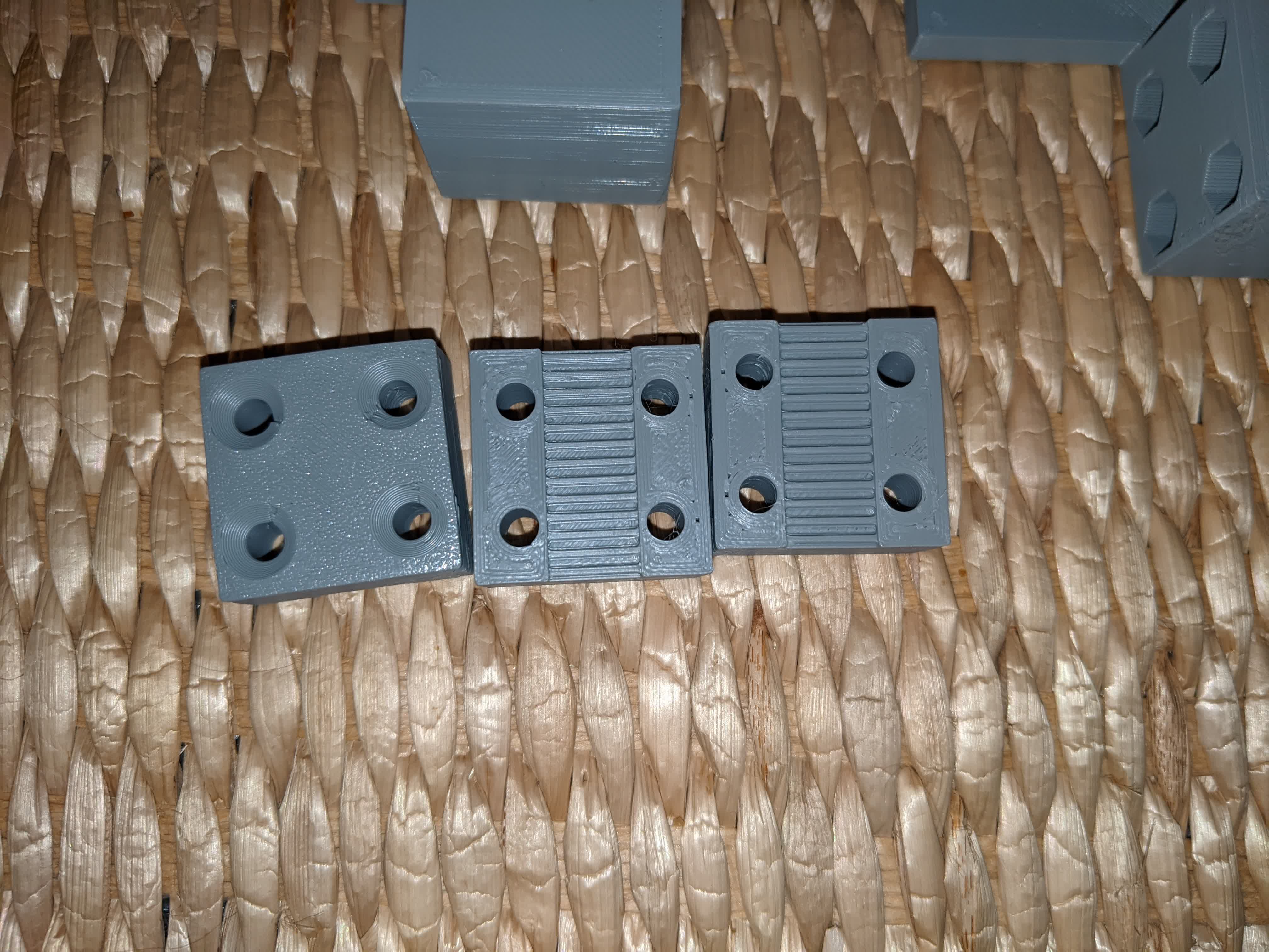
I asked for spare parts for the YL side plate, lineaer bearing clamp, and the belt clamp. I was told to try printing them myself first. So I pulled up the CAD Jake provided usin Fusion and generated the STL's for each of these parts. I generated the 3d printing gcode using the same settings Jake specified here. I then went to the Sindoh 3DWOX-1 and printed these:
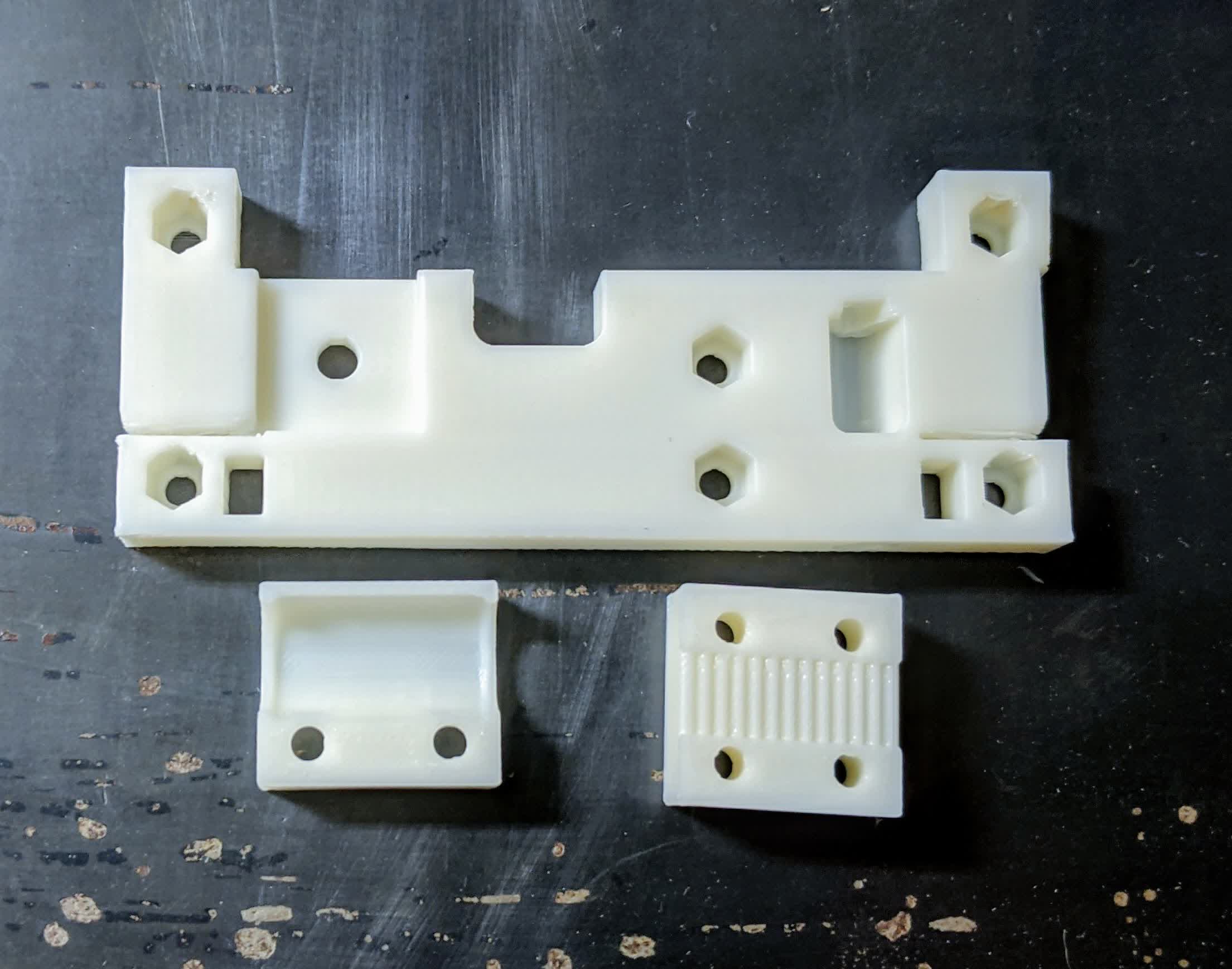
The YL side plate was fine and I replaced the one I had in my YL carriage. The belt clamp was also fine. However, I could not fit the nuts into their hex sockets on the linear bearing clamp no matter what I did. Here is an image show me trying to pull the nut in with a screw after trying to push with pliers and vice.
Then I had to wait to get a new linear baring clamp and coupler from Jake to complete the assembly, which he so graciously gave me. I installed the new coupler successfully after such a nerve racking session of carefully torqueing.
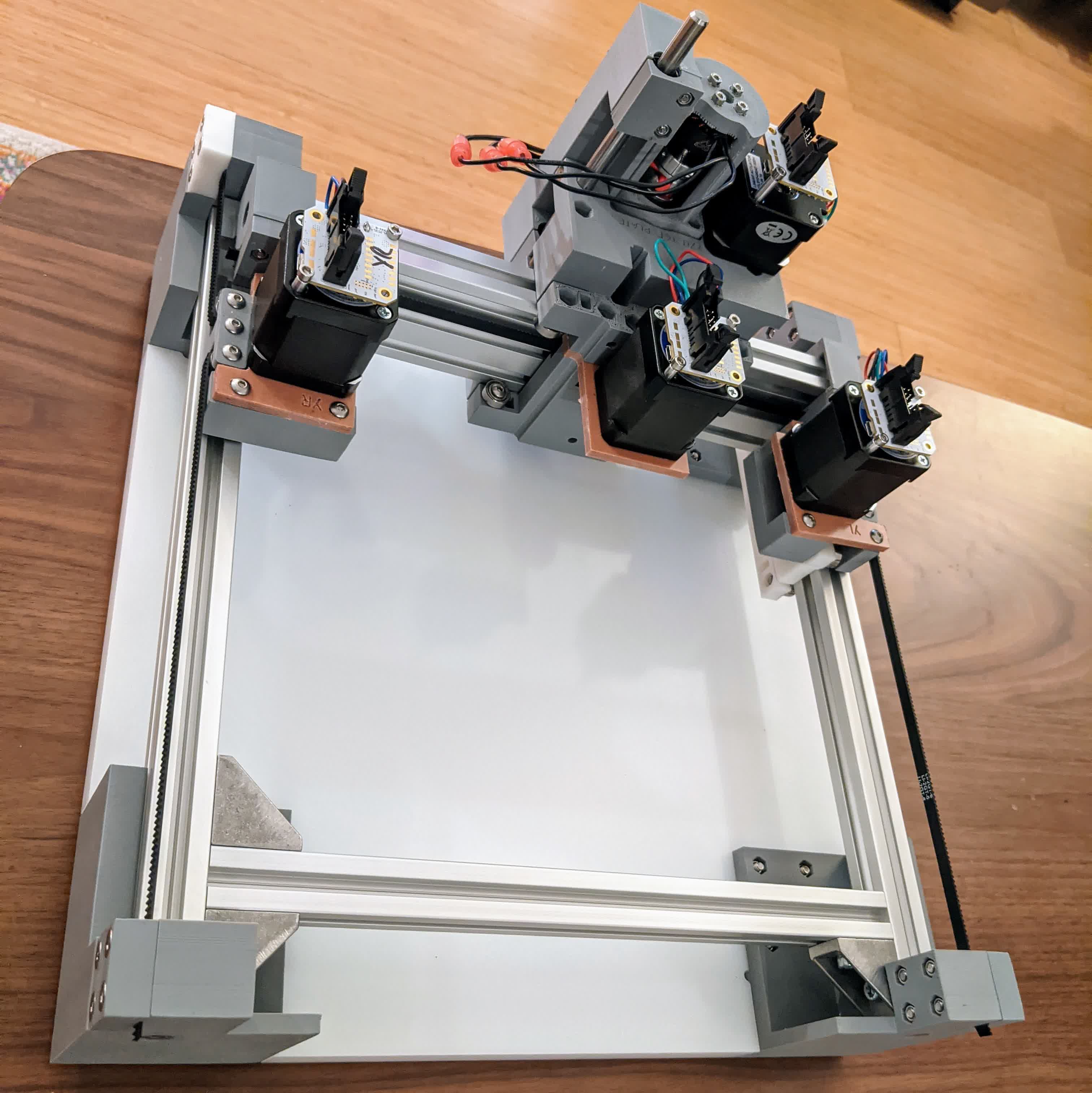
I then completed the general assembly of the frame, carriages, and bed:
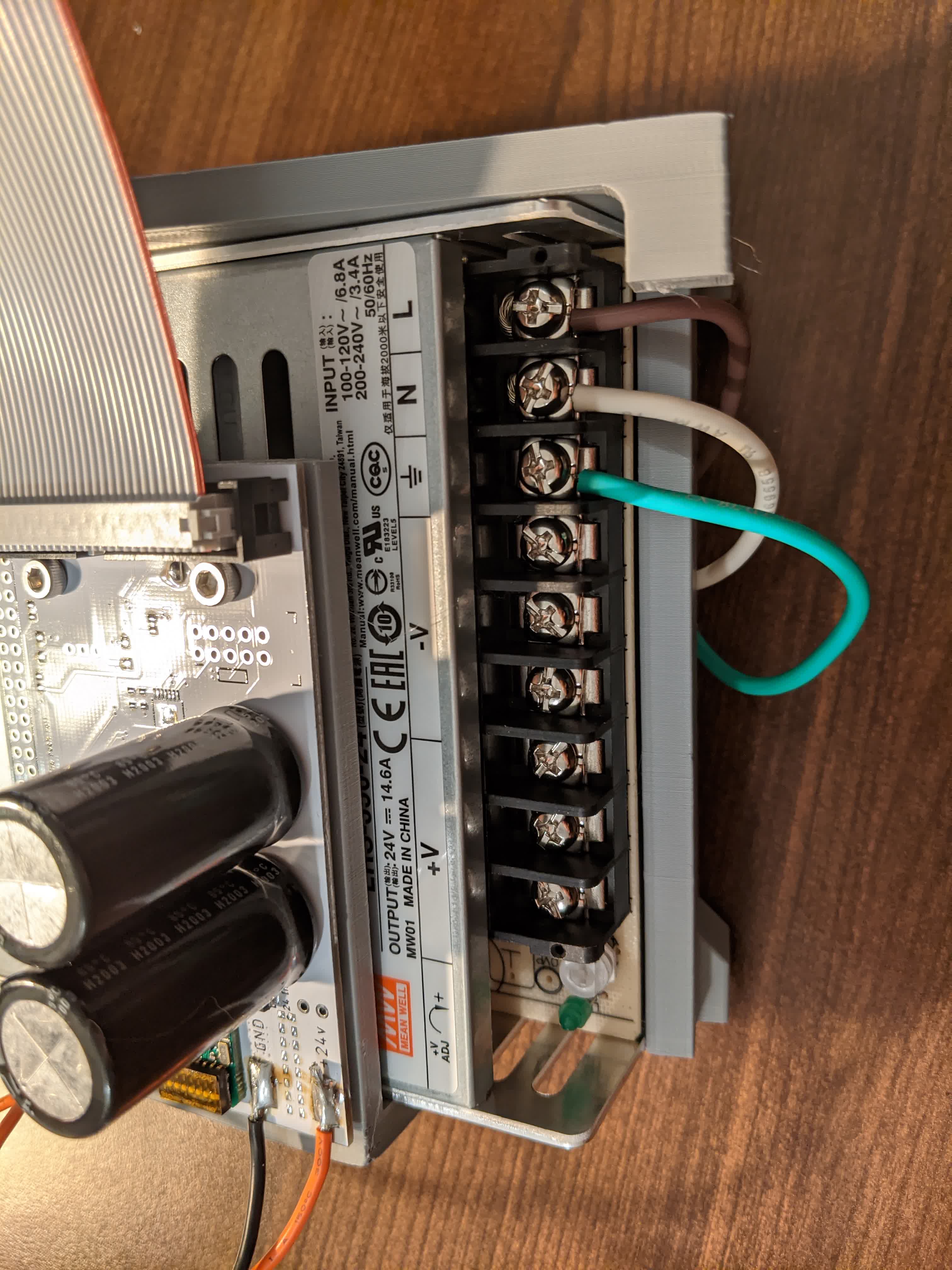
Next I moved on to the power supply and wiring. I wanted to be extra careful here, so I looked up how to best connect a lead into a screw clamp. I found most people twist the stranded then bend with pliers to wrap around the screw for a clean and safe installation as shown:
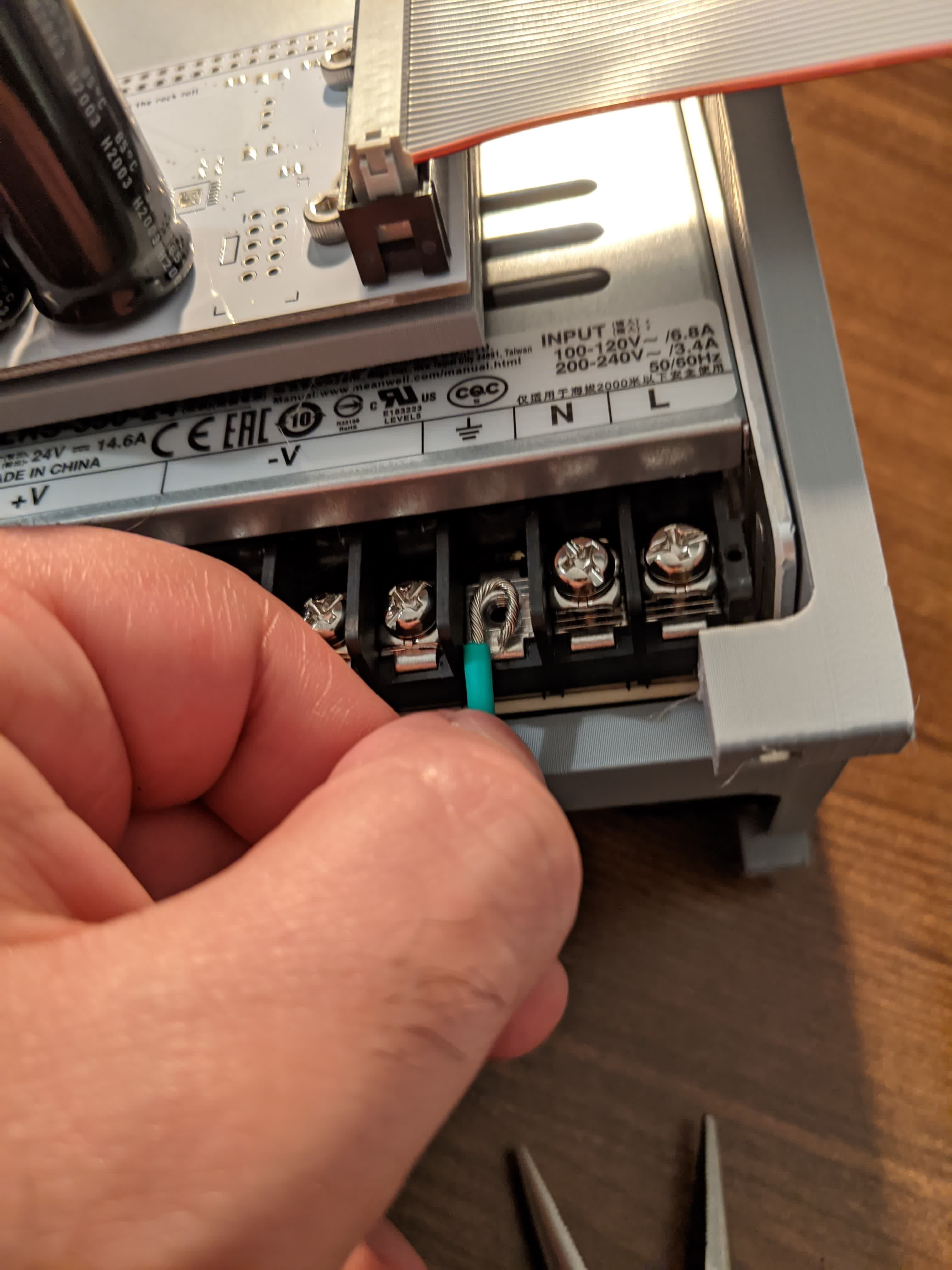
Here are the ground, neutral, and live leads fully installed from the wall plug DIN connector:
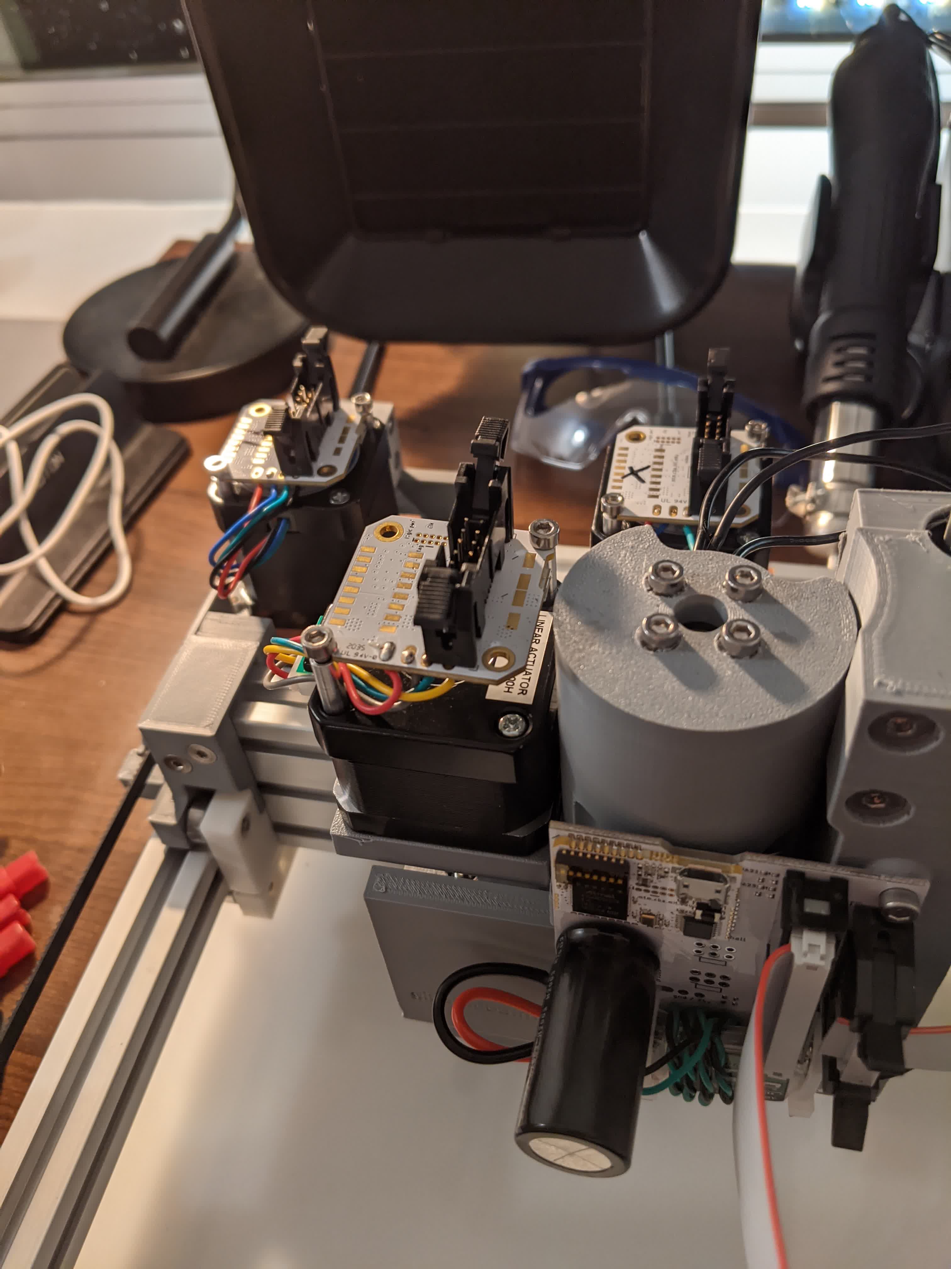
Next came wiring the logic board to each motor. This was pretty easy, but I found out as I followed Jake's tutorial was the we originally installed the Z motor board in a not to optimum orientation. Here it is before:
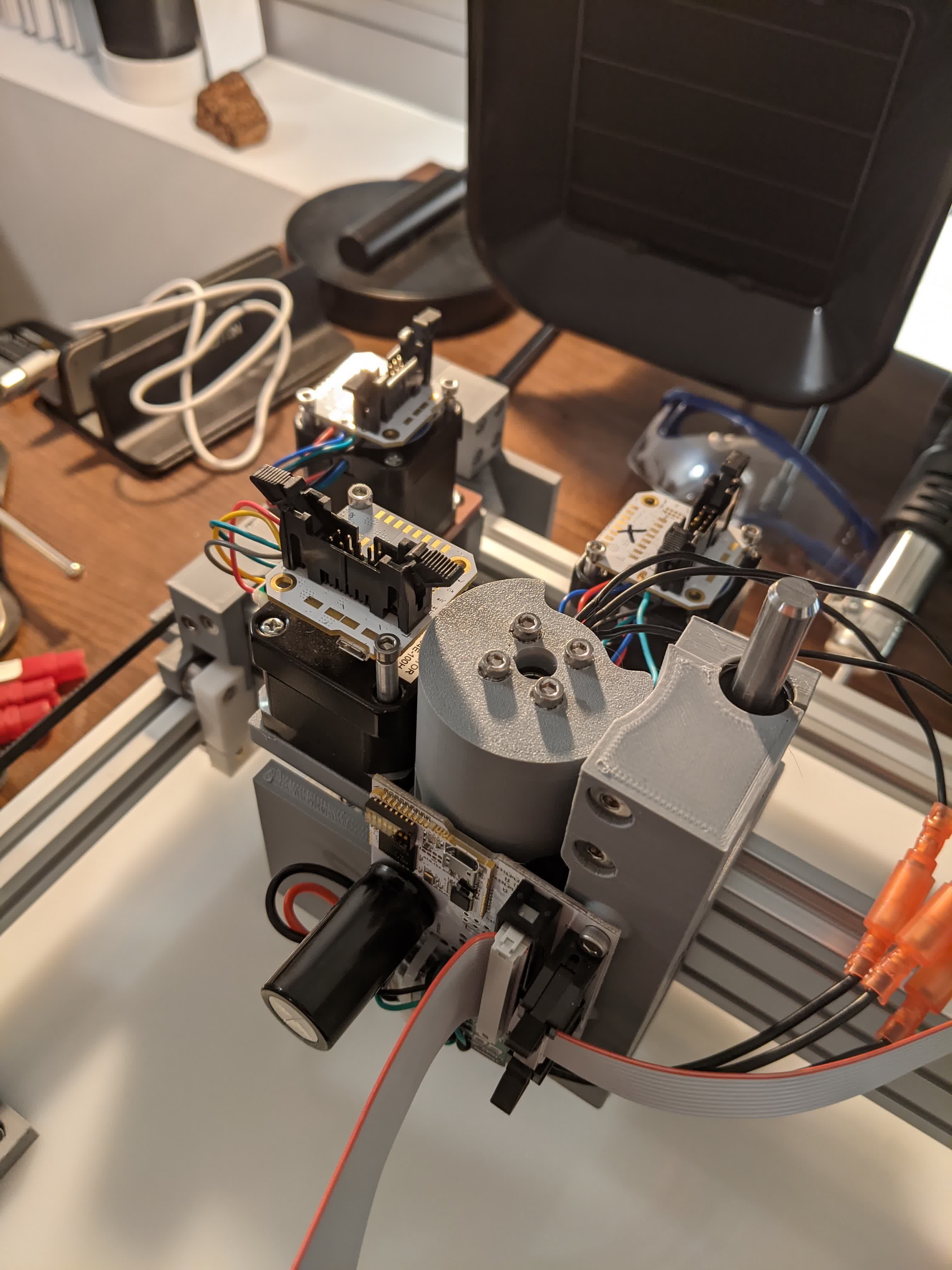
Here is the better orientation mostly for routing the ribbon cable efficiently:
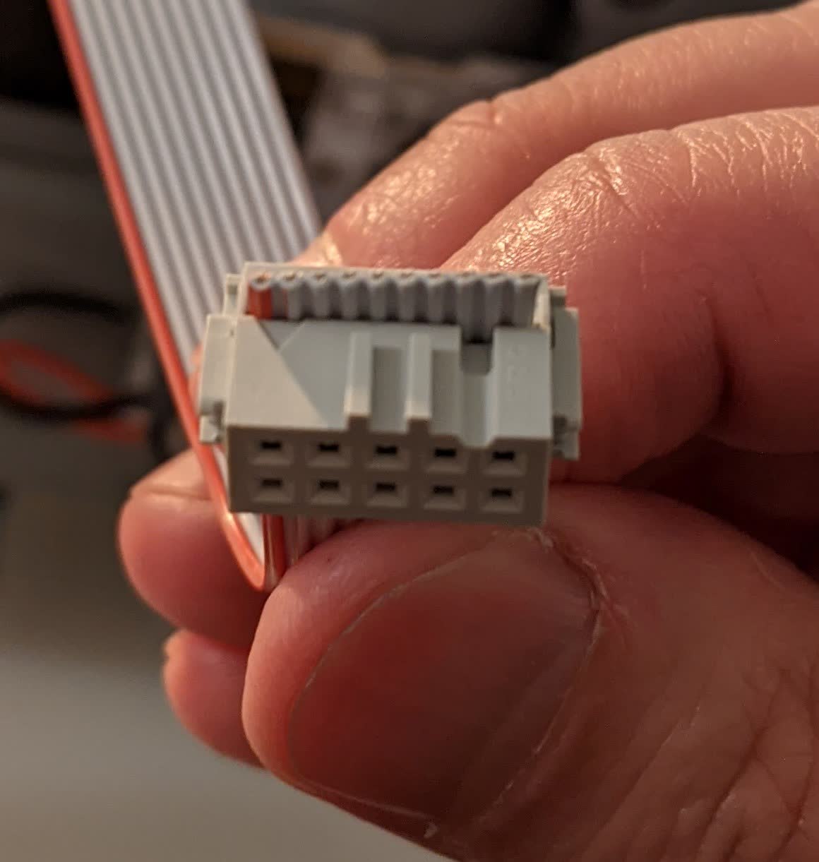
When routing the ribbon cable, I learned about proper alignment and how these connectors actually work. I learned from Jake's tutorial that there is a little arrown ecthed on the connector indicating the number 1 pin.
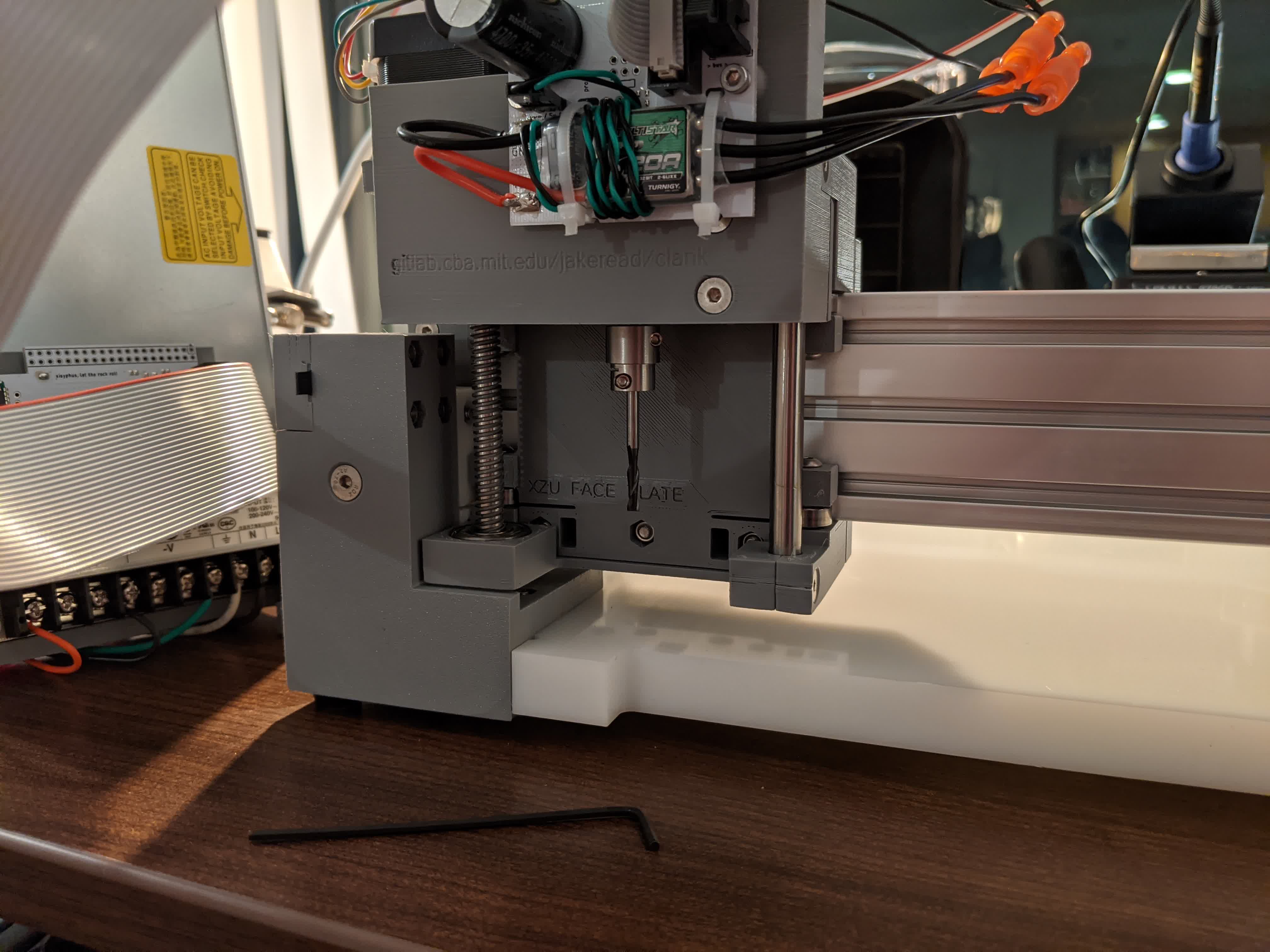
Once that was done, I finished building the hardware!!!
Operate Clank
It took me a week to get to here, and the next step was to wake up Clank. It took me a while to figure out, but we needed to connect a micro-USB cable from the logic board to the computer. This must be done BEFORE powering on the power supply. I followed the controller installation steps Jake listed here .The general work flow to operate clank is as follows:
-connect the micro-USB from logic board to PC
-open Git Bash and navigate to the "tool" directory from the cloned Clank control repository
-type the command: node Clank
-turn on power supply
-open a browser and navigate to : localhost:8080
It also wasn't clear to me what to do to actually operate this machine. I did not know initially, that the arrow keys move clank in x-,y-, and z-directions after we click on the "click-in to jog" button. I also don't know if my "home" button is bad or if I am doing something wrong, but when I click "home", my machine starts violently vibrating and rattling as it moves to (0,0,0), the bottom left corner with the z-axis in the fully up position. I have to admit, it was really exciting to see this thing move for the first time!!
The jogging controls worked smoothly though, and I found out that my classmates also saw similar issues with the "home" button. Key take away, just don't click "home"!
I was really confused as to how to operate the machine and home the x, y, z axes. I found the best method was:
-with the power off, drag the XZ carriage to the bottom left of the bed.
-Install the bit corresponding to the job you want to do. In our case, the 1/8" flat endmill is to face (level) the bed, the 1/32" flat endmill is to cut out the board, the 1/64" flat endmill and V engraving bit are to mill traces.
-In the browser, click "get position", and if it does not read (0,0,0), change it to (0,0,0) then click "set position". This creates an absolute reference on the xy plane (we will do z later) for the machine in case you lose your reference later.
-Power on the machine. This will engage the motors and lock them in place.
-Use the jog buttons to move the spindle to the bottom left corner of where you plan to start cutting.
-Click "get position", then jot down the coordinates for your reference in case you lose it later. Then change the (x,y) to (0,0). With this, we have homed the x and y axes.
-Next, using the width and length of the planned cut, move to the center of that. For instance, if the panned cut piece is 20mm x 10mm, move to (10,5).
-Put a piece of paper in between the bit and the top of what you plan to cut. Start jogging the z-axis down in small increments. Between each increment, try pulling the paper. If it moves, then keep jogging down. Repeat until the paper is tighly locked between the bit and the top of your cut surface.
-Click on "get position" and change the z-coordinate to 0. then click "set position". Then jog the z-axis up 1mm to ensure you can move freely in the xy plane.
-Load the gcode of your job.
-Hit "run" and get excited to turn your digital image into reality! These are the steps I take before any job.
Before cutting out anything though, we had to face the bed (ie make it level with respect to the x-,y-,z-axes of the machine). Jake provided us with the gcode to flatten about a 5.75" x 5.75" area square down by 0.005". We were to use the 1/8" flat endmill for this. I installed the bit and homed my xy plane.
I then moved it to the center of the bed and homed the z-axis there. Then I let it whirl!
The result was not what I expected. Using a flat endmill and a radius of overlap, I expected a perfectly smooth surface. Instead, I got a bunch of rough grooves.
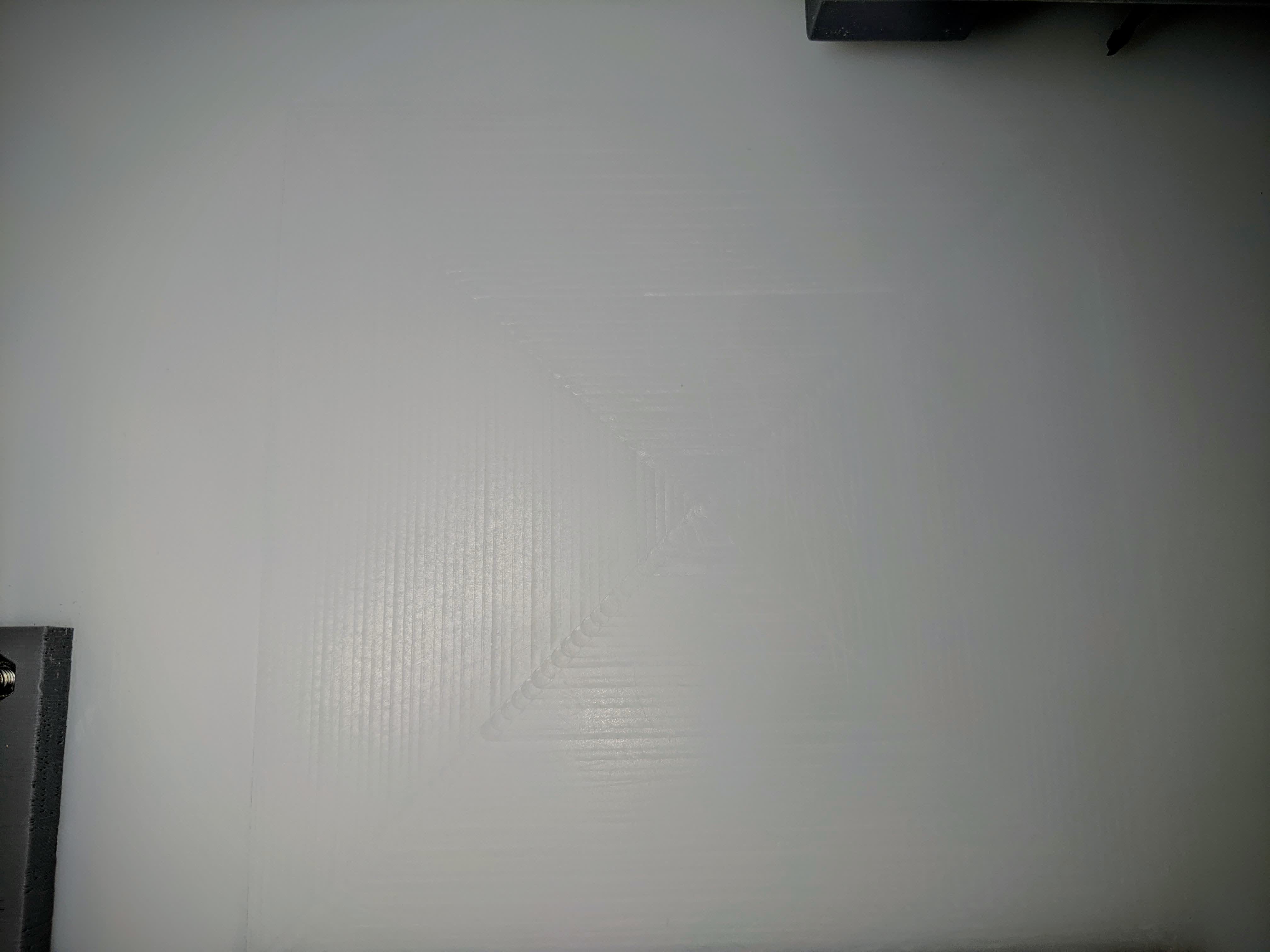
I realized this might be an issue, but proceeded anyways. Now my Clank and I were ready to start cutting!
Cut Test Piece
I scraped off the loose plastic from the grooves on my faced bed using my metal ruler. I then wiped it with alcohol. Then I put down my copper board using double sided tape.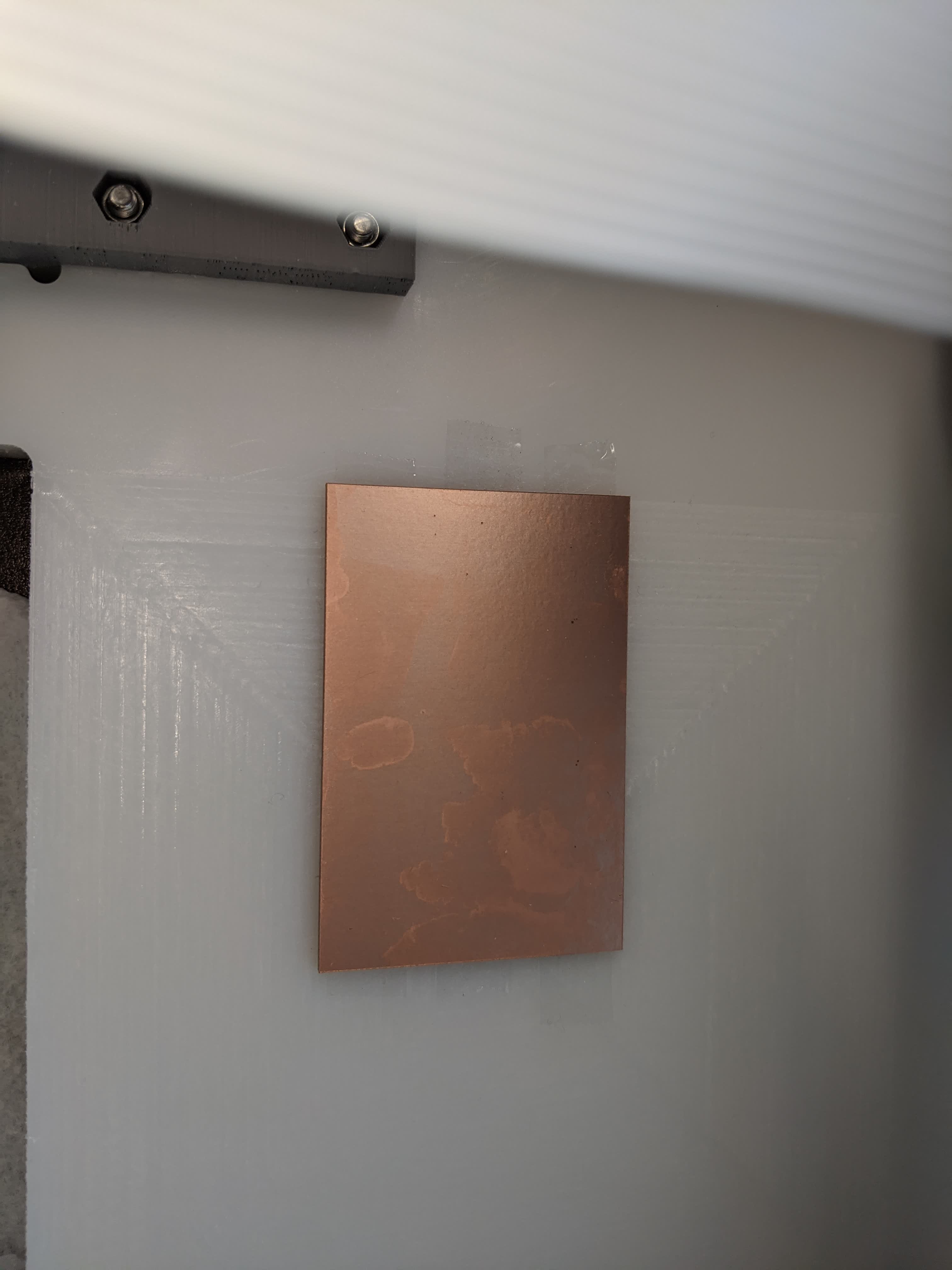
Here I am showing the paper homing method for the z-axis.
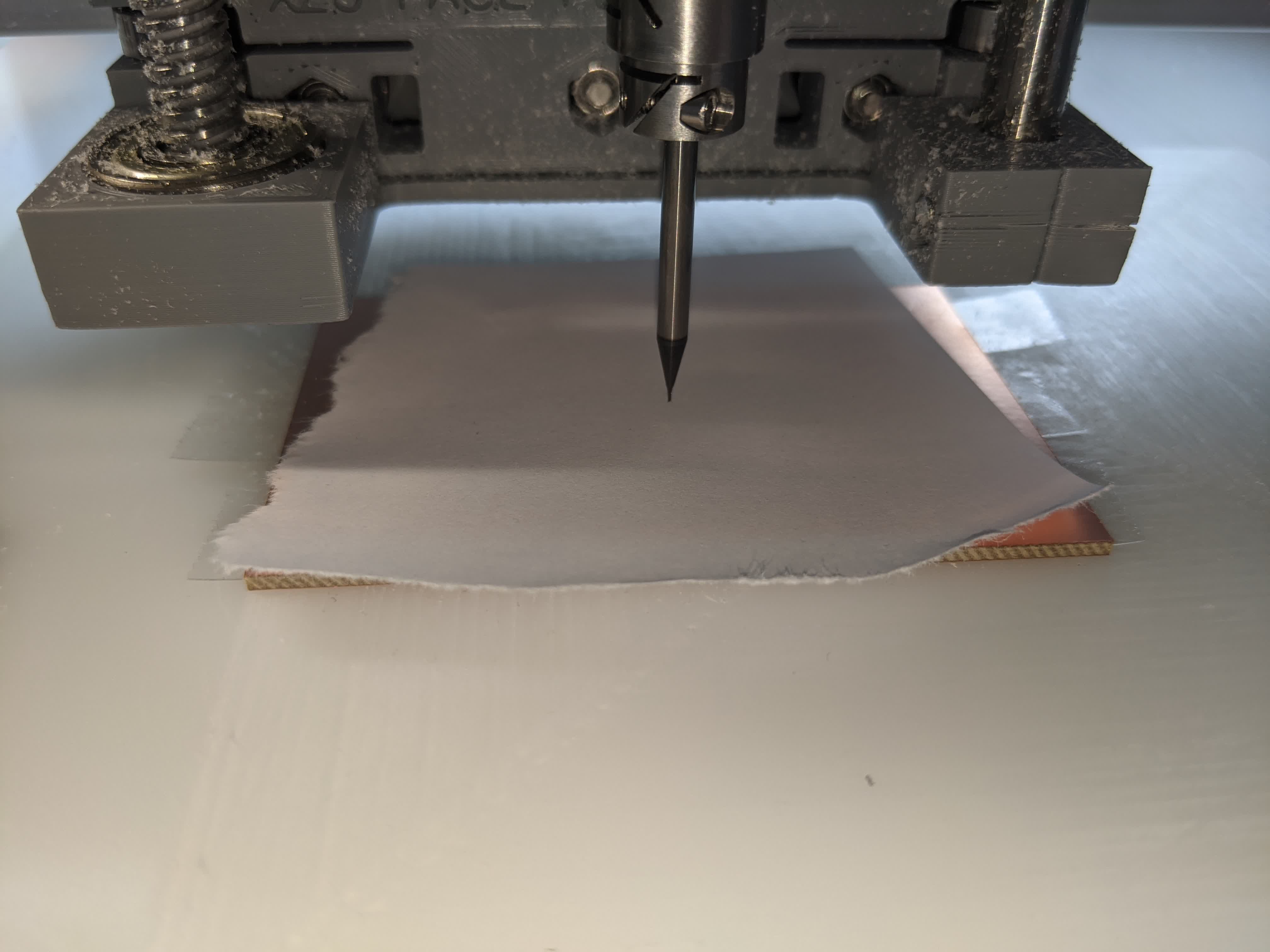
And here I began my first etching job. I used the default values from mods.
This was using the 1/64" flat end mill, a cut depth of 0.004" in 1 pass, and a speed of 2.5mm/s.
Then I changed the bit to the 1/32" flat endmill and did the exterior cutout using a cut depth of 0.024" to a maximum depth of 0.072" (ie 3 passes) and a cut speed of 2.5mm/s. This was the result:
As you can see, it did not cut deep enough to remove the copper. So I went and did this a few more times at various depths of etching.
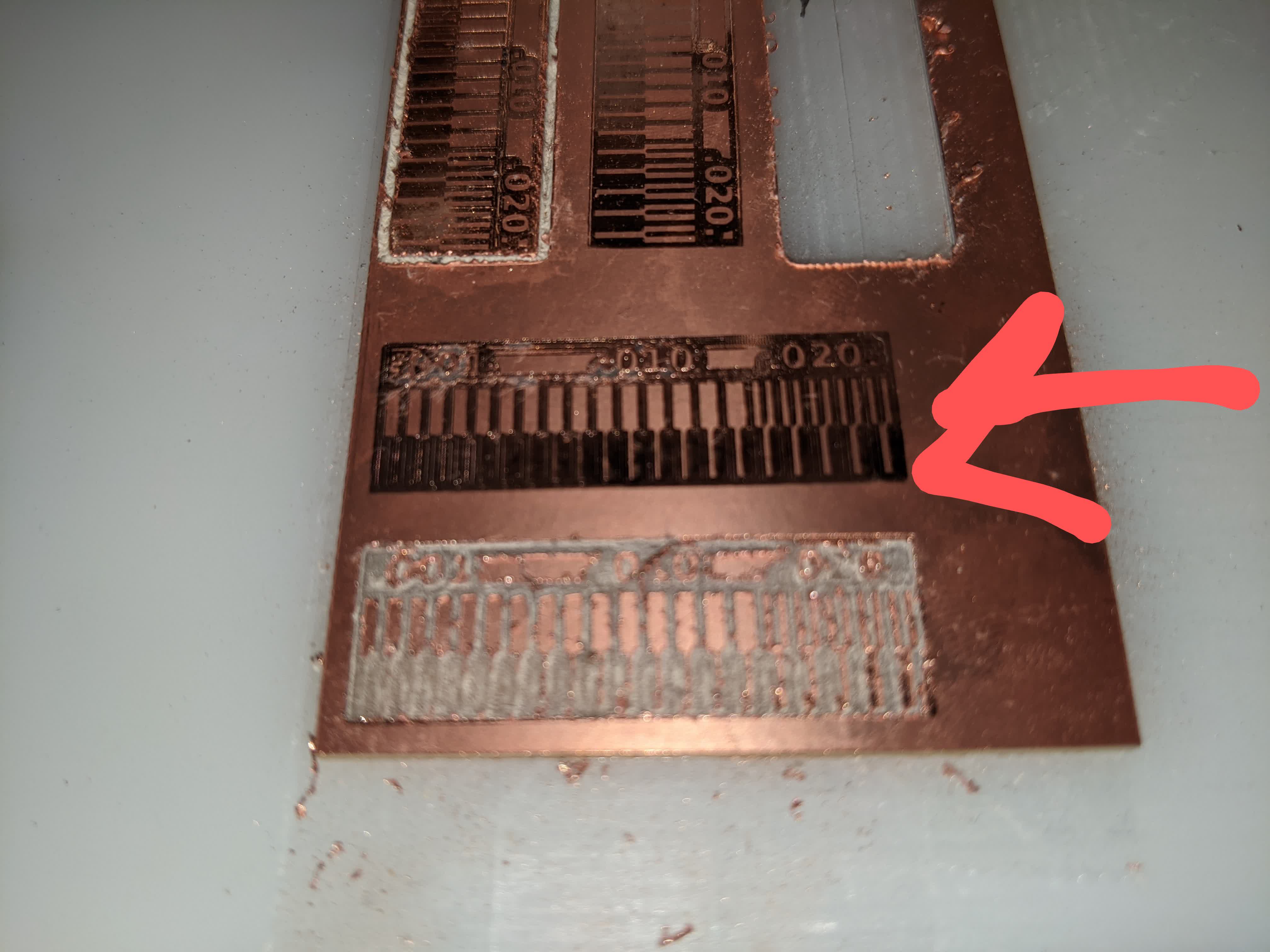
The top two tries were repeats of the default mods settings because I messed up and lost my reference when trying to change bits. The bottom most was cut at 0.006". It was much too deep and messy. The one above that with the red arrow was cut using a depth of 0.005". You can clearly see 2 problems:
1-The depth of 0.005" was not deep enough to cut through most of the copper, and 0.006" is too deep, so this left me kind of stuck not knowing what was the ideal depth.
2-You can see the top left of the piece cut through the copper, but there is a slow gradient to not cut copper as you move to the bottom right corner.
The second issue proves that I did not have a flat bed. So this took me back to the drawing board. I went back and refaced my surface. I actually did it 3 more times.
Also, I had this happen once:
I don't know why the tape didn't hold.
In any case, lots of issues and very limitted time!! I decided to ditch the 1/64" flat endmill. My classmates seemed to be getting cleaner cuts using the V engraving bit. So I tried that at a depth of 0.004", and it looked good. Here is a video of the cutout of that piece.
You can see I put my finger down to make sure it doesn't go dragging off like before. haha
Before I move on, I need to reference a problem I had as I kept changing bits so many times. The socket head screw was starting to strip, where my allen key would jump as I tighten.
So I got replacement screws. They are #2-56 screws with a 5/64" socket head.
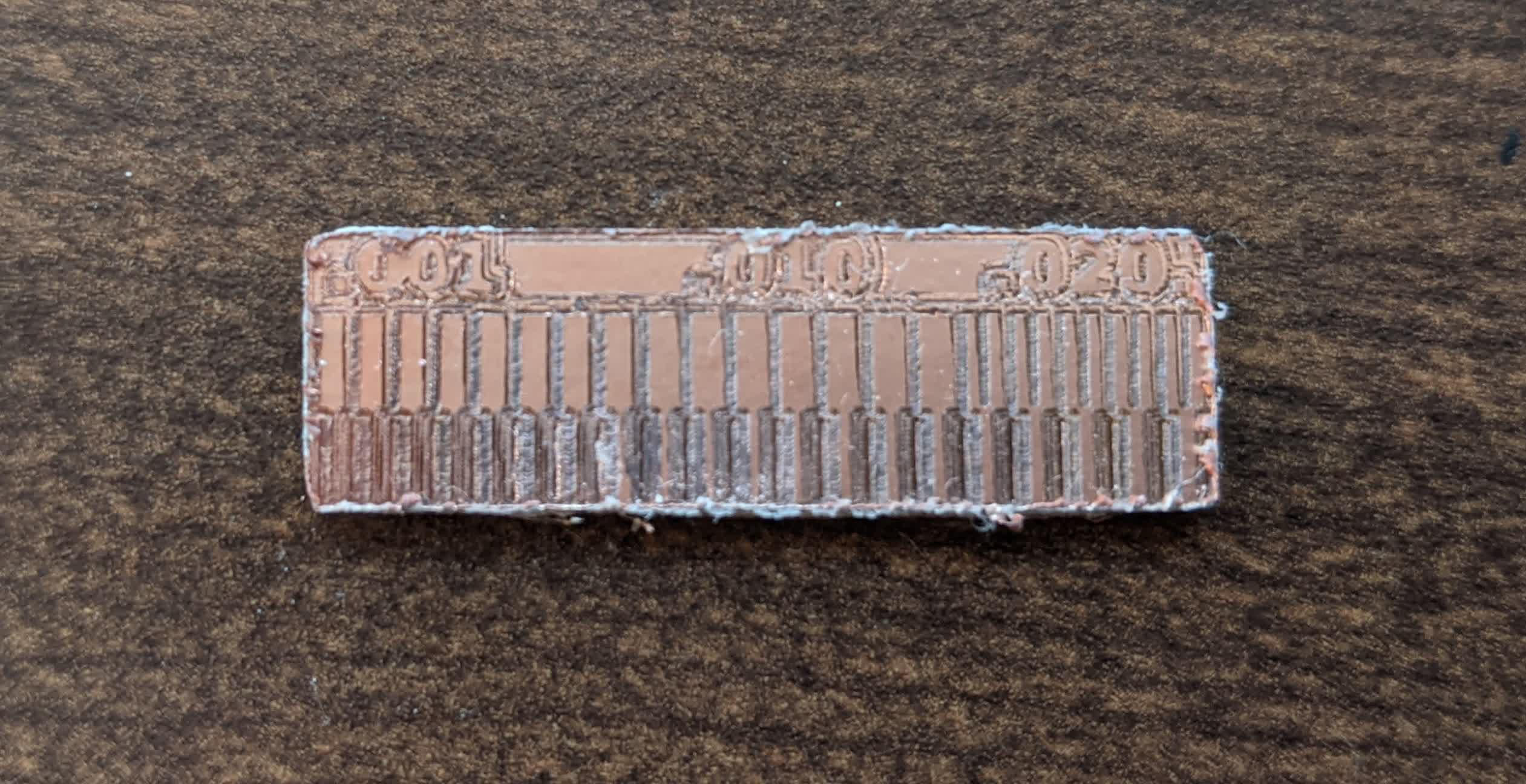
I finally got a good test piece.
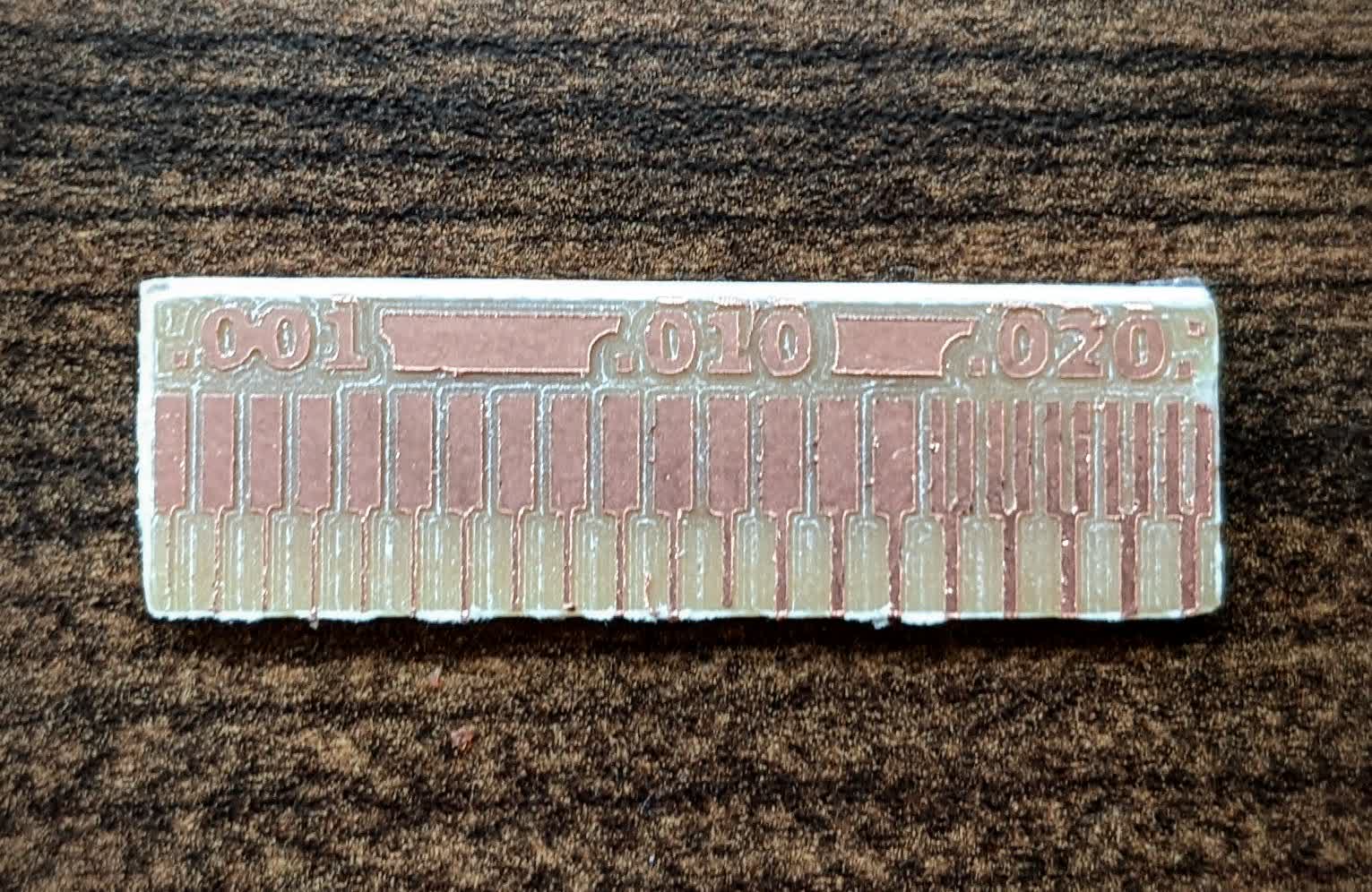
and here are the dimensions (design direction is 1.47"x0.504"):
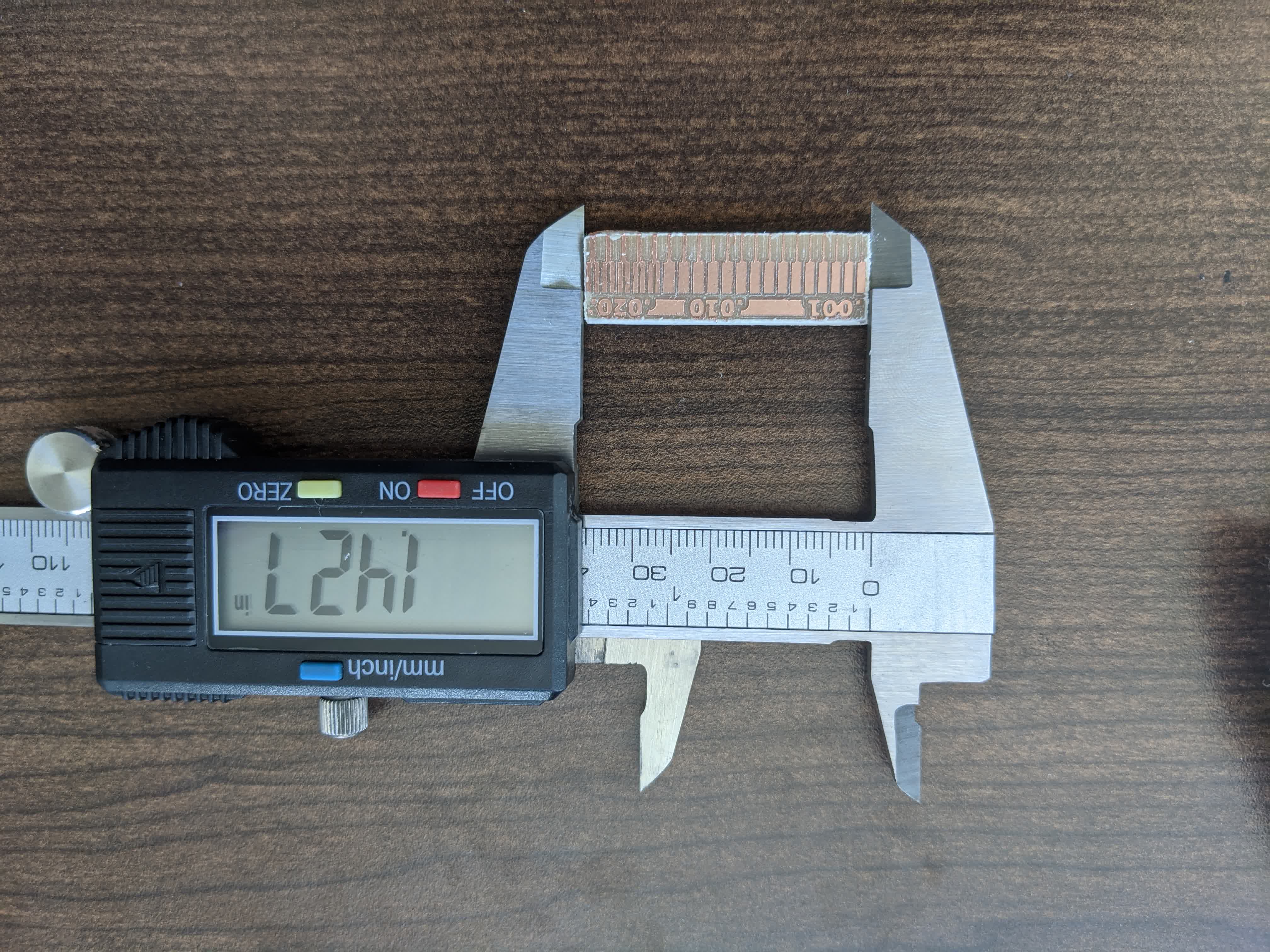
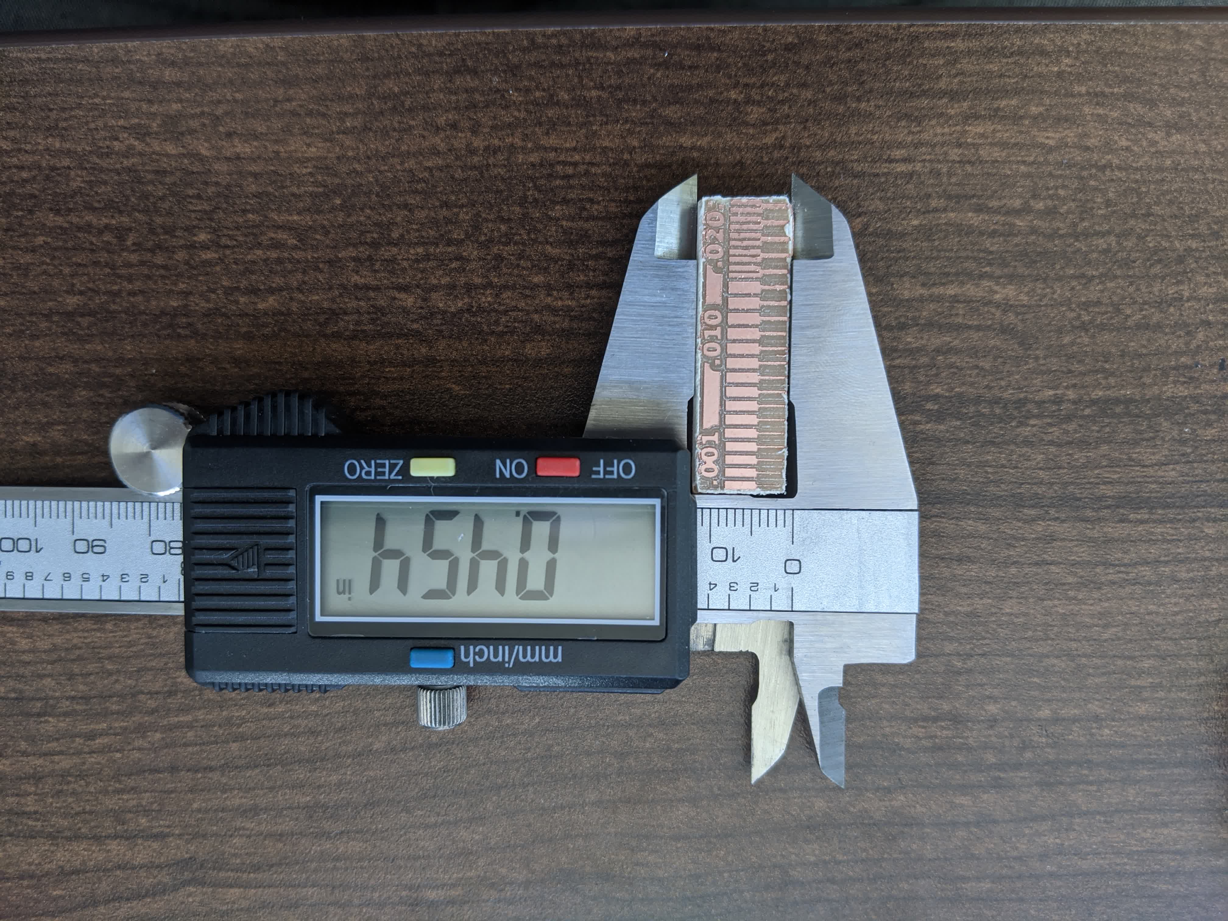
It was a bit undersized, but within tolerance. Also, I used a multi meter and made sure that all the connected points were actually connected and isolated where they were supposed to be.
In general, I would say that clank can cut out any lead as small as 0.001", but I would avoid that. I'd be more comfortable with 0.01". As for cuts between 2 leads, we can go as small as 0.016".
Now I know the best parameters and design rules for Clank and can proceed to the actual assignment.
Summary of Clank Issues
1-Bad 3d printed pieces: Some pieces were warped, others had unreasonable tolerances for nuts and screws. Either the design needs to account for bigger tolerances, or significant quality checks on prints need to be performed. Placing nuts took longer than necessary. Some parts were damaged while I tried to force nuts in. Overall, a pretty unpleasant experience.
2-Stripping screws: I stripped the hex socket on one of the couplers and the collet. It would be ideal to have spare screws for each othese, particularly critical and frequently used parts.
3-Missing parts: this is an honest mistake, but more diligent quality assurance of the whole package could prevent this from happening.
4-Facing Issues: This took me a long time to get right. A level surface with respect to the machine's x,y,z axes is beyond critical. Facing with a flat endmill resulted in grooves that I eventually sanded off. This has its own risks (like taking off too much in one place and unleveling that spot) but resulted in better results than not sanding.
Cut In-Circuit Programmer
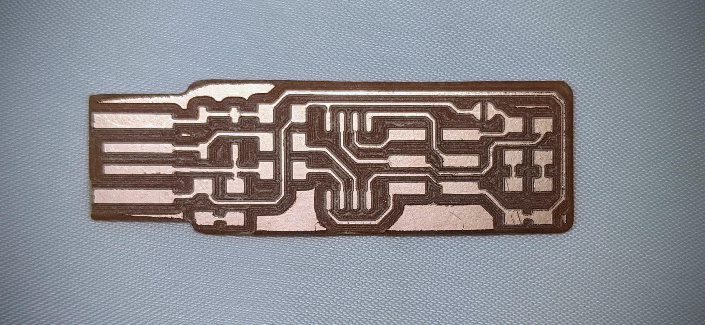
I followed a tutorial to make the FabTinyISP. Here is the PNG for the traces: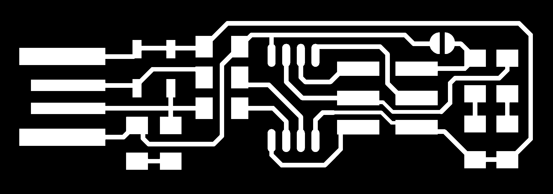
I used the V engraving bit, with a cut depth of 0.002" and a maximum depth of 0.008" (ie 4 passes), 4 offsets and a cut speed of 1.5mm/s.
Here is the PNG for the cutout.

I used the 1/32" bit with a cut depth of 0.01" and maximum depth of 0.07" (ie 7 passes), and a cut speed of 1.5mm/s.
This was the end result, my beautiful PCB with clean cuts everywhere!
Stuff the PCB
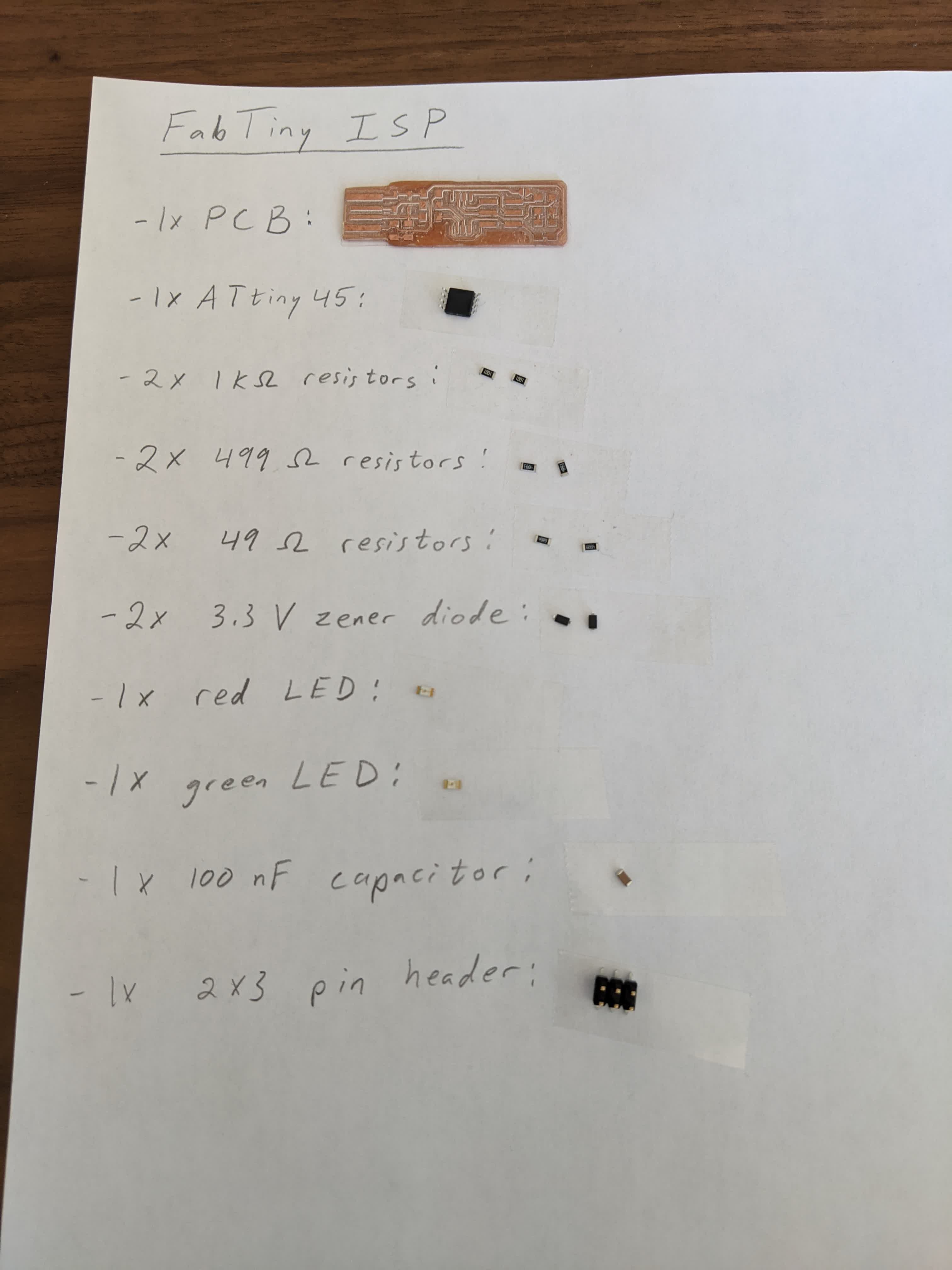
Following the tutorial, I proceeded to collect all the physical components I will be soldering on.Here is the list of parts for this programmer:
-1x ATtiny45 microprocessor
-2x 1k Ohm resistors
-2x 499 Ohm resistors
-2x 49 Ohm resistors
-2x 3.3V zener diodes
-1x red LED
-1x green LED
-1x 100nF capacitor
-1x 2x3 pin header
Here is an image with all the components laid out and ready to place:
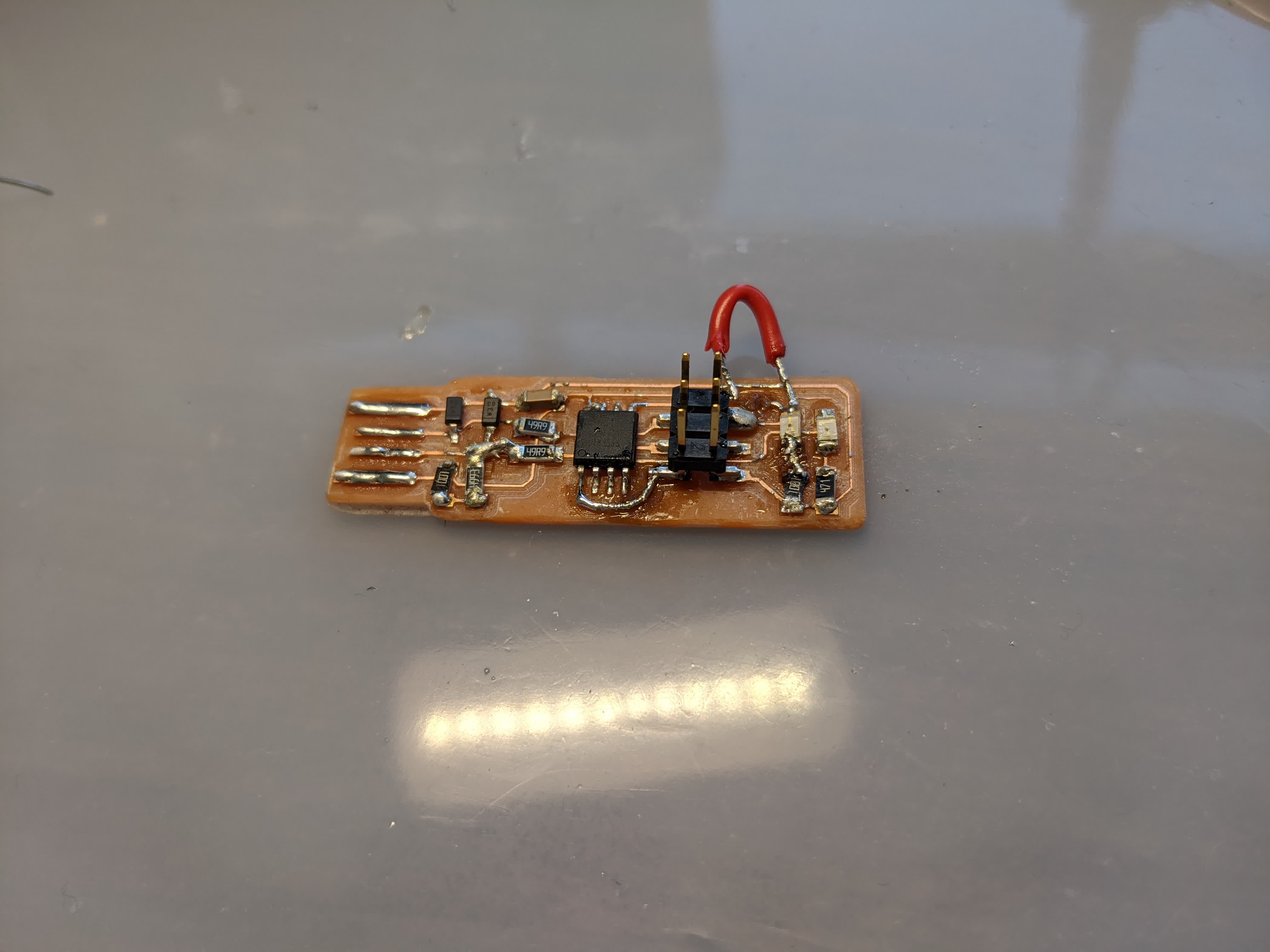
Next step is to solder these on the board. Some of the legs and pads are really small, so it required patience and focus. After much struggle, here is the result:
Program and Test
The first thing to see is if this thing works. So I plugged it in to an extension cable connected to a USB 2.0 port on my computer.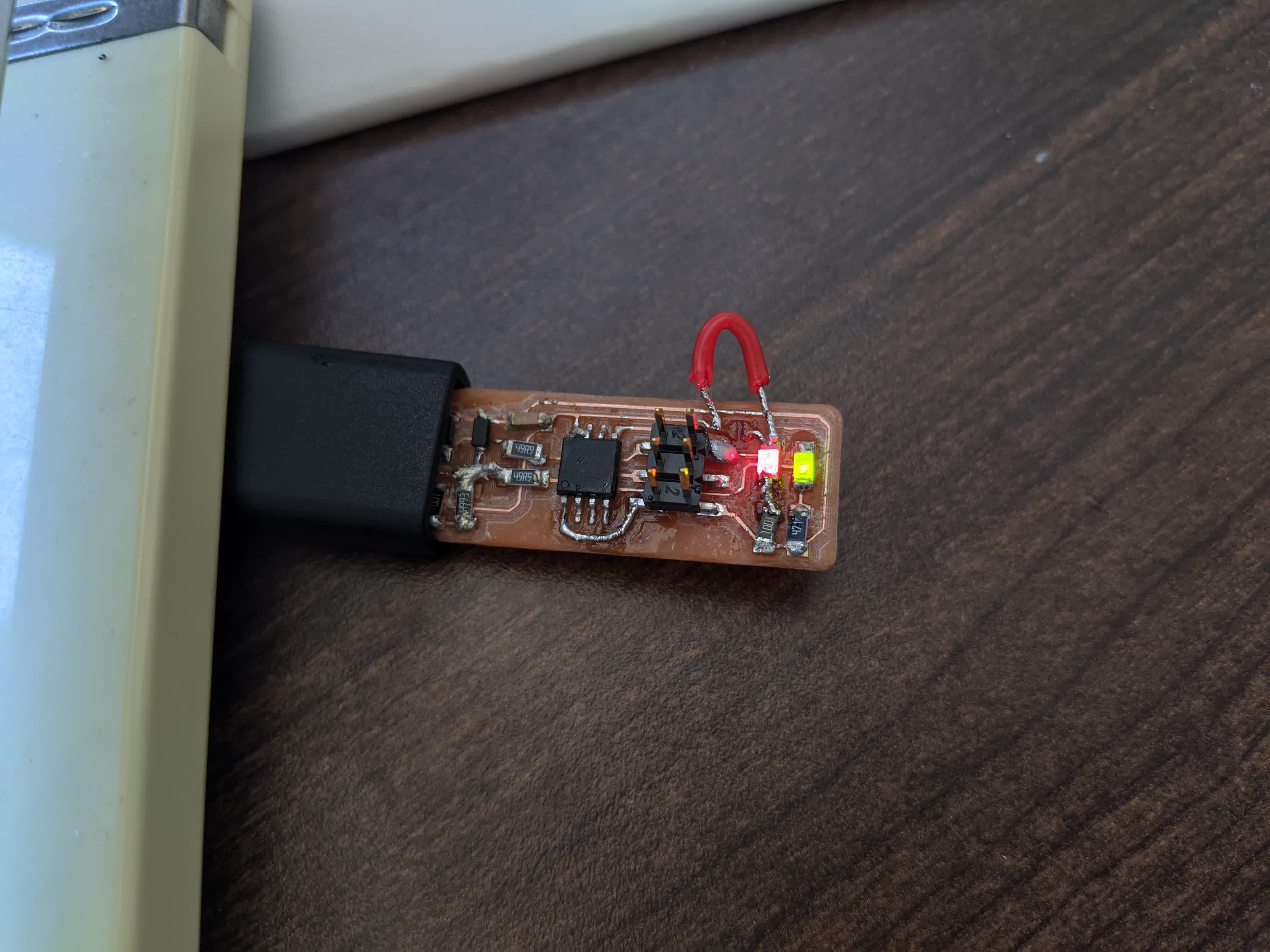
The first sigh of relief after a long process is that it lights up! The green LED indicates that the board is getting power. The red jumper wire temporarily connects Vcc to Vprog on the ISP header so that the header can be used to program the tiny45. The red LED indicates that the tiny45 is ready to be programmed. So the hardware is all setup and ready to go.
The software is what gave me a lot of trouble. Note, I use a Windows machine, so I followed the Windows tutorial to install the proper toolchain.
I needed to setup my development environment, which went south pretty quickly. Here are the things I needed and did:
-install Git...check
-install the Atmel GNU Toolchain...this took a while because Atmel's website was a bit ambiguous, but I did it and extracted it into my Program Files directory...check
-install GNU Make...check
-install avrdude...unzip and archive into the Program Files directory...check
-update my PATH...to tell windows where to locate all the tools I just installed(GNU Toolchain, GNU Make, and avrdude)...check
-install drivers for programmer...WALL
This is where I got stuck. I had to download a software called Zadig to install either libusb-win32 or libusb0 onto USBtinySPI (my programmer). After troubleshooting with Calvin and Erik, I found out that this meant I needed a seperate programmer to program my tiny45. So I bought the Atmel ICE. I plugged in the ICE into both USB 2.0 and 3.0 ports on my PC, and no matter what I did, it would not appear as an option on Zadig. So I gave up on the Windows installation and went to the Arch Shop to try to do this on the Linux computer and Atmel ICE there.
Round 2...on Linux
Here is the checklist for Linux: -I started by making sure avrdude was installed there with this command in the Terminal: sudo apt install avrdude gcc-avr avr-libc make...check
-downlaod the firmware source code from here, extract the zip file, and cd into the source code directory...check
-Run the command "make" to build the hex file that will get programmed into the tiny45...check
-update the file called "Makefile" and changed the line that says "PROGRAMMER ?= usbtiny" to "PROGRAMMER ?= atmelice_isp" since that is the programmer I am using...check
-physically setup the hardware connections:
*the FABTiny plugs in to a USB extension cable that runs to the computer
*a 6 pin connector plugs into the 6 pin header on the FABTiny noting that the Pin1 pin on the header is connected to the Pin1 slot on the 6pin connector
*the other end of the 6 pin connector plugs in to the Atmel ICE programmer's AVR slot
*a micro USB cable connects the Atmel ICE to the computer
...check
-Run the command "make flash" which should erase the target chip and replace it with the contents of the .hex file we made earlier by running the "make" command...WALL
I got the following error message:
        avrdude -p attiny45 -c atmelice_isp -P usb -e \
        -U flash:w:fts_firmware.hex

        avrdude: Short read, read only 0 out of 512 bytes
        avrdude: jtag3_edbg_recv(): Unexpected response 0x10
        avrdude: stk500v2_jtag3_recv(): error in jtagmkII_recv()
        avrdude: AVR device initialized and ready to accept instructions

        Reading |                                                    | 0% 0.00savrdude: Short read, read only 0 out of 512 bytes
        avrdude: jtag3_edbg_send(): Unexpected response 0x54, 0x90
        avrdude: stk500v2_command(): command failed
        avrdude: stk500isp_read_byte(): timeout/error communicating with programmer
        avr_read(): error reading address 0x0000
        read operation not supported for memory "signature"
        avrdude: error reading signature data for part "ATtiny45", rc=-2
        avrdude: error reading signature data, rc=-2
        avrdude: jtag3_edbg_recv(): Inconsistent fragment number; expect 1, got 0
        avrdude: stk500v2_jtag3_recv(): error in jtagmkII_recv()
        avrdude: Short read, read only 0 out of 512 bytes
        avrdude: jtag3_edbg_send(): Unexpected response 0x78, 0xd7
        avrdude: Short read, read only 0 out of 512 bytes
        avrdude: jtag3_edbg_recv(): Unexpected response 0x10
        avrdude: Short read, read only 0 out of 512 bytes
        avrdude: jtag3_edbg_send(): Unexpected response 0x88, 0x8d
        avrdude: Short read, read only 0 out of 512 bytes
        avrdude: jtag3_edbg_recv(): Unexpected response 0xa8
        avrdude: Short read, read only 0 out of 512 bytes
        avrdude: jtag3_edbg_signoff(): failed to read from serial port (0)

        avrdude done.  Thank you.

        make: *** [Makefile:61: flash] Error 1
Nothing I did changed this. So I went out and got myself a Raspberry Pi Model 4B to try my luck at home.
After repeating all the above for Linux, I ran the command "make flash" and crossed my fingers...
          avrdude -p attiny45 -c atmelice_isp -P usb -e \
          -U flash:w:fts_firmware.hex
          avrdude: usbhid_open(): No response from device
          avrdude: jtag3_edbg_prepare(): failed to read from serial port (-1)
          avrdude: failed to sync with the JTAGICE3 in ISP mode

          avrdude done.  Thank you.

          make: *** [Makefile:61: flash] Error 1
..another wall...
It is unfortunate that I could not program my FABTiny to be a programmer for future chips. I don't know what the reason is.
After spending hours and hours trying to get this setup, I was extremely demotivated to proceed. This is especially because the chip I am using for my next board is the ATtiny1614, which utilizes a UPDI protocol, making the FABTiny useless and incompatible since it runs an ISP protocol.
Further debugging is required, but alas, I had to move on...
A huge thanks to Erik who spent countless hours helping me dubug!