Web Design, Version Control, and Final Project Brainstorm
Laser & Vinyl Cutting
3D Scanning and Printing
Make Something Big
Molding and Casting
Electronics Production
Electronics Design
Embedded Programming
Input Devices
Output Devices
Networking & Communications
Interface and Application Programming
Final Project
Group Assignment
The group assignment was to review the safety data sheets of our molding and casting materials and to test them. This was done in collaboration with with Jordan, Maya, Gil, and Emma. The process and results can be viewed here.Molding and Casting
Assignment: design a mold around the stock and tooling that you'll be using, mill it (rough cut + (at least) three-axis finish cut), and use it to cast parts
Design
The constraints of this assignment are the size of the stock wax we are to use, the set of milling tools available for the mill, casting material for the mold, and casting material for the part.
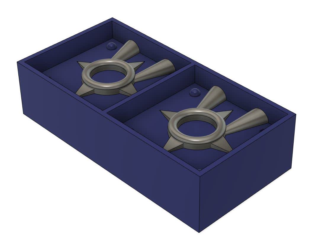
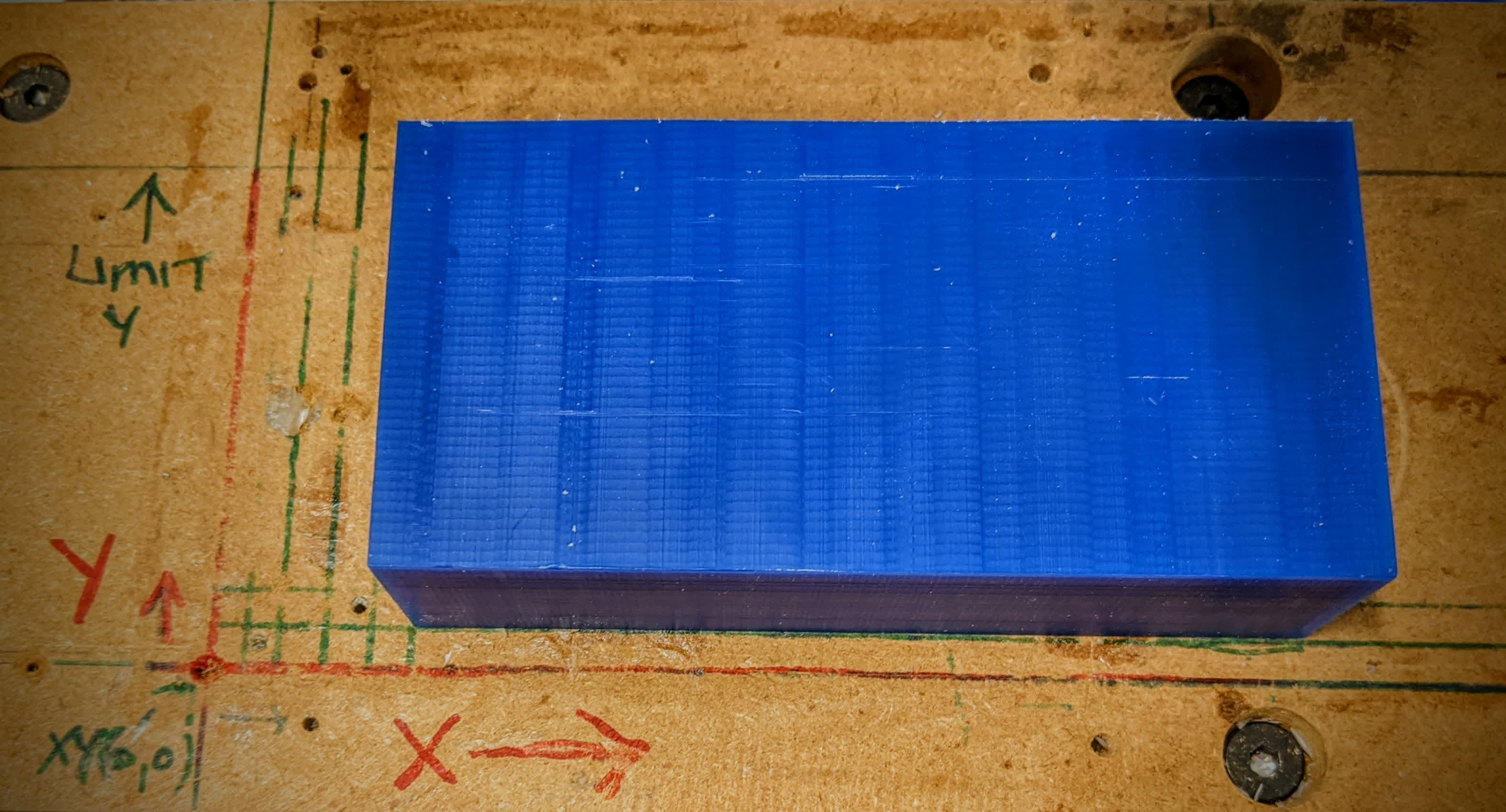
The stock wax block we are using is 6"x3"x1.5", so this limits what we can make to something pretty small. I am an avid ninja fan, and my first ever email was magic_shuriken@hotmail.com.
So I decided I would make a shuriken; a small, non-functional, decorative, rotate in my fingers when I'm bored, shuriken.
Block Design
I started working in Fusion 360 with a fully paramteric model. I drew the wax block, and extruded 2 rectangles into it to give me my actual working space. The working space was designed to have 1/8" walls all around. I wanted to maximize on my working space, but not on the structural integrity of the wax block.
Ring Design
Then came the actual shuriken. I wanted it to have a ring with an inner diameter large enough to fit around my thumb, so I made it 1". The ring was made by extruding a circle and an offset, and fillets were added later on equal to half the thickness of the ring, giving it a perfectly circular ring link appearance.
Blade Design
Then I played around with the loft feature. I set a tangent plane on the inner ring wall, and drew a rectangle which would be the base of the blade. The rectangle width was not larger than where the plane intersects the ring. I then drew a line on the floor of the working space from the middle of the bottom edge of the rectangle, and this line would be the length of the blade. Finally, I lofted using the rectangle and the far end point of the line to create the pyramid like shape of the blade.
I then made the other blades using a circular pattern.
Sprue Design
The sprue were made in a similar fashion. I created a plane on the inner wall of the ring at an offset angle, drew a semi-circle on it with a 1/4" diameter. Given I planned on using molten metal which is very viscours, this was a major design consideration to allow the metal to flow easily and overcome capillarity. I then drew another semi-circle on the interior top wall of the wax, also at an offset angle and not directly above the shuriken. I wanted the sprue to go to the ring, not the blade. The other semi-circle was designed to be 1/2" in diameter to make it easy to access when pouring molten metal. I then lofted between the two semi-circles to give me the offset conical sprew. Finally, I mirrored this sprue to the other side of the same shuriken to act as an air duct and overflow hole.
Registration Point Design
I designed the registration points to be semi-spheres. Spheres are apparently easier to locate when lining up the mold than cylinders. I started by drawing 4 construction rectangles with corners pinned to the 4 corners of the working space. I made these construction rectangles have a side length of 1/3", and their corners opposite of the pinned corner would serve as the location of the semi-spheres centers. I then drew circles at these points and a line connected along their diameter to give me a semi-circle to work with. Using the revolve feature, I either made a male semi-sphere sticking out, or a female semi-sphere cutting into the wax.
It is important to note that the wax registration points are inverts of the mold. This means that the males in the wax are actually the females in the mold. I made the males in the wax 0.005" larger than the females to create a tolerance to ease fitting the two halves of the mold.
In the end, I made 2 males and 2 females on the same mold face.
Final CAD Design
The last step in this design is to mirror everything accross on the other end. This was done pretty easily by creating a contsruction plane cutting the wax block in half vertically, and then using that plane as the mirror axis. Now I have the wax block ready to go:
Toolpath Design
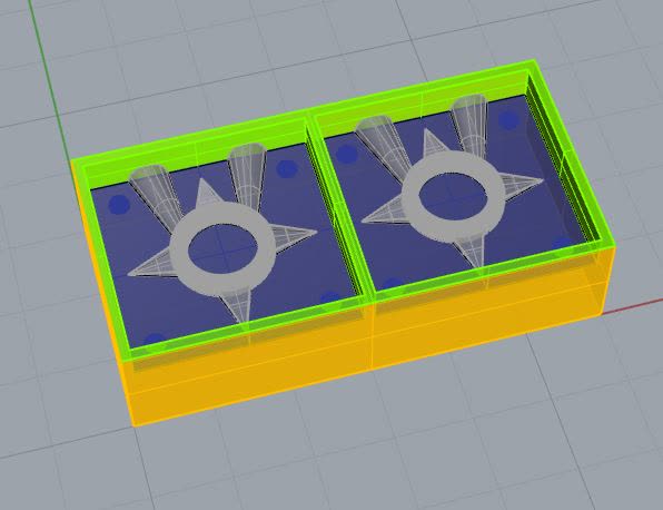
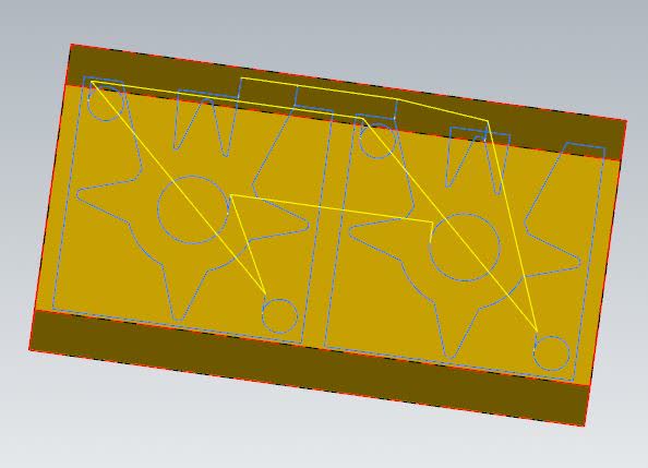
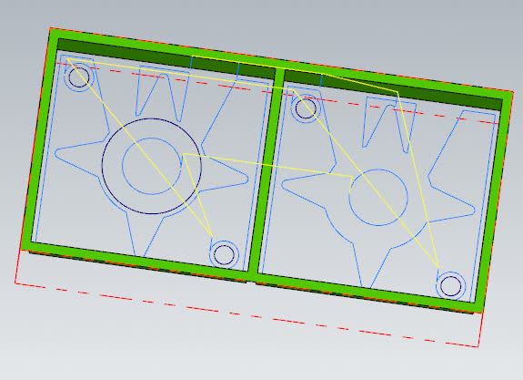
With the help of Zain, a godsend TA, we imported my CAD into Rhino to define surfaces. I don't know if this is doable in Fusion 360, I'm sure it is, but Zain likes doing this in Rhino. The green shows the walls we want to avoid colliding with, the blue shows the bottom of the cutting surface, and the grey is the part. Once that's done, we can import into Mastercam to set the toolpath.
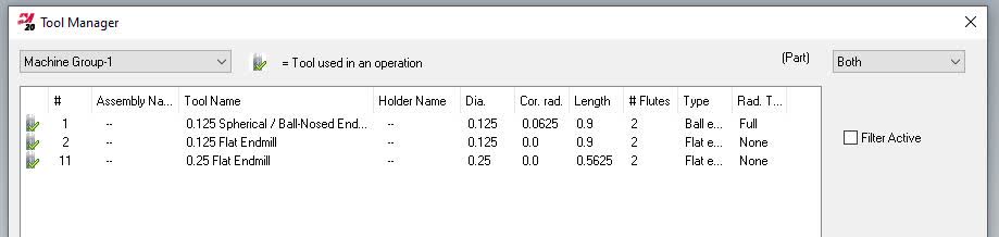
We setup a plan using 3 tools. A 1/4" flat endmill would do the rough cut. The 1/8" ball endmill would do the finish cut. Finally, the 1/8" flat endmill would do a contour cut to clean up edges.
Here is the toolpath for the surface rough parallel cut:
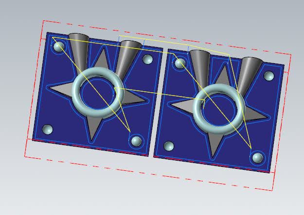
Here is the toolpath for the surface finish cut:
Here is the toolpath for the contour clean-up cut:
With that set, it is time to move from the computer to the real world and actually make this!
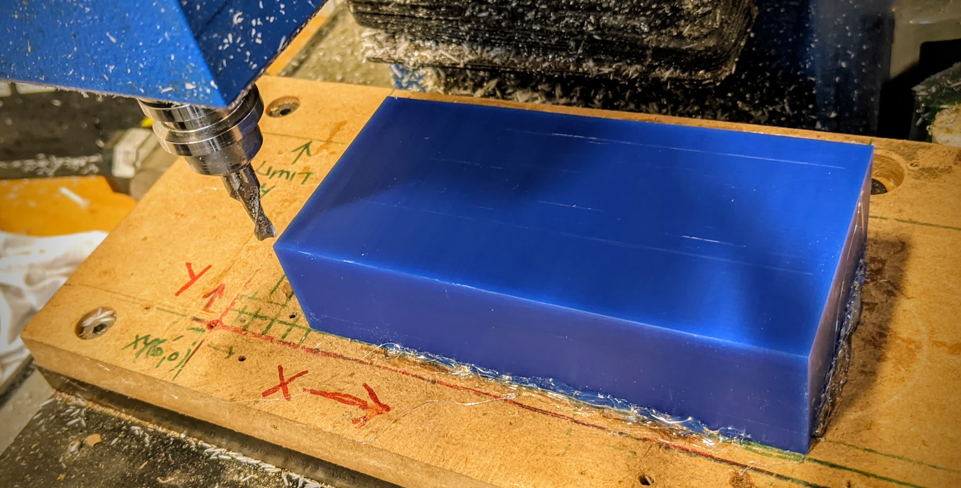
CNC
We start with the wax block which will be milled, and then used as a mold for my mold.
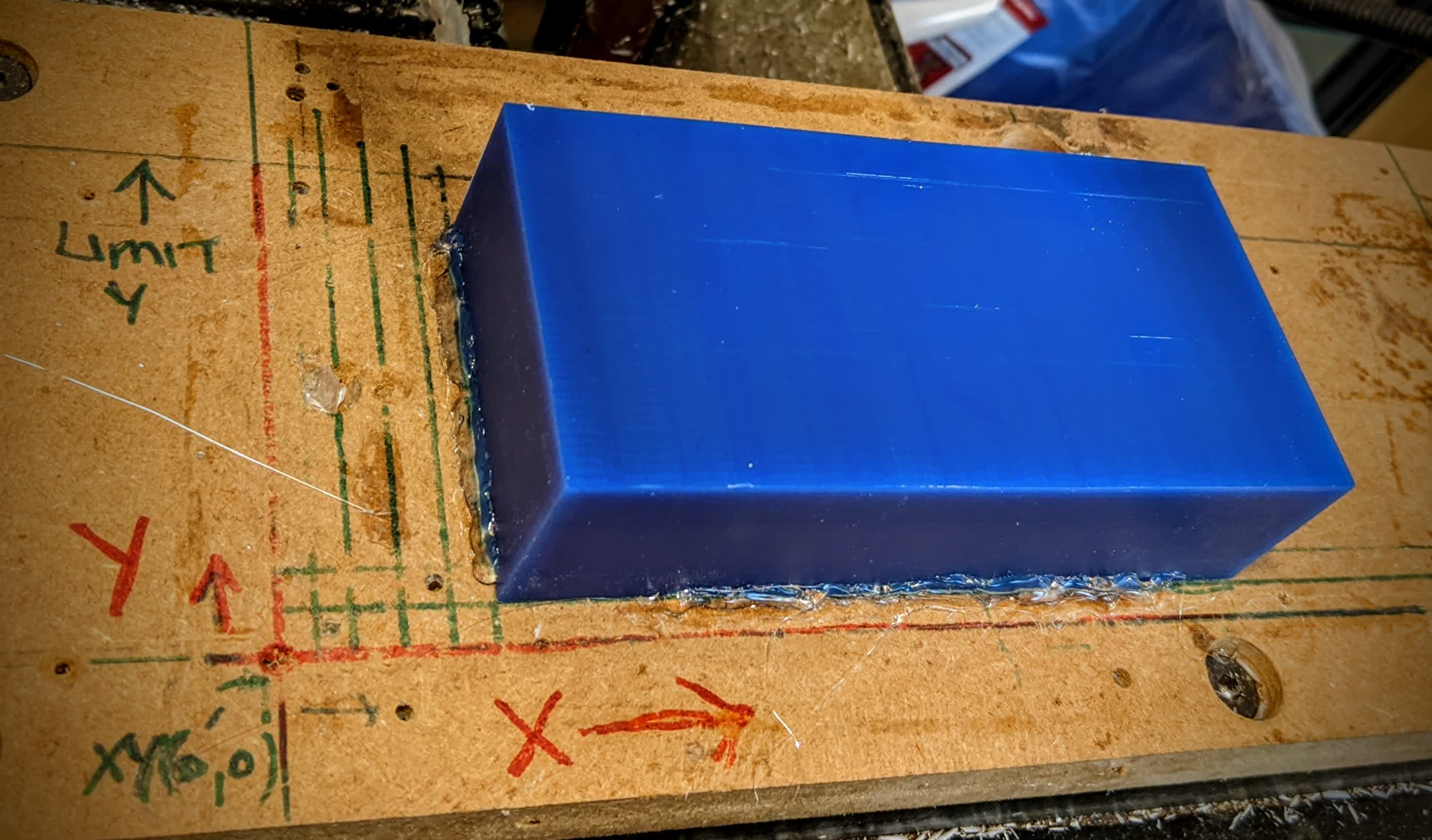
It is important to secure it during the milling process. I only applied a bit of hot glue on each edge as shown below. Too much glue will make it impossible to remove, too little will make it fly off when CNC'ing.
The next step is the most critical. You have to set to origin, and never lose it (which I did later on). I eyeballed the origin, and a good trick to use when doing so is this: if you're setting the x-axis origin, then rotate the flutes of the flat end mill to be paralle to the x-axis, then bring the mill down close to the wax, and stop moving it when its center is approximatle at the edge of the wax. Same thing is done for the y-axis, but rotate the endmill 90 degrees. For the z-axis, move the mill away from the wax, and bring it down to the table. Put a piece of paper on the table, bring down the mill until it is hard to move the paper around. The z-axis needs to be set for each tool as they vary in length. With the x-, y-, and z-axes set, and the 1/4" flat endmill in place, we are ready to go.
The is the surface rough parallel cut. As you can see, we have huge chips.
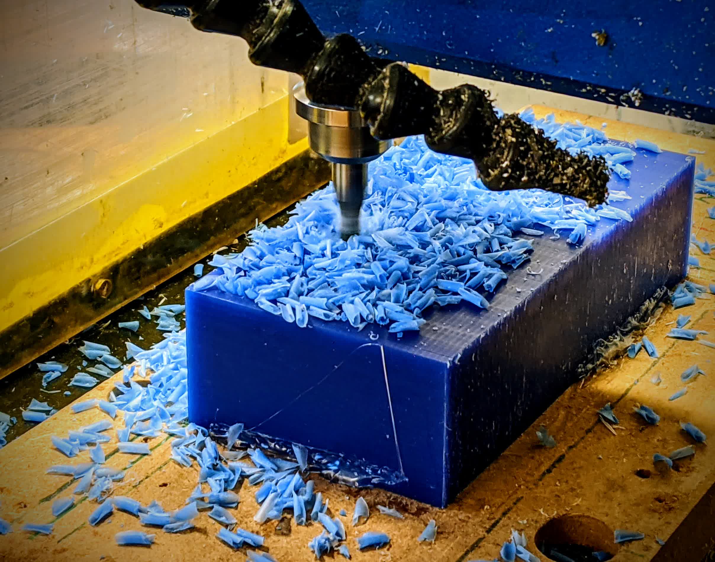
Here is a video showing this in action:
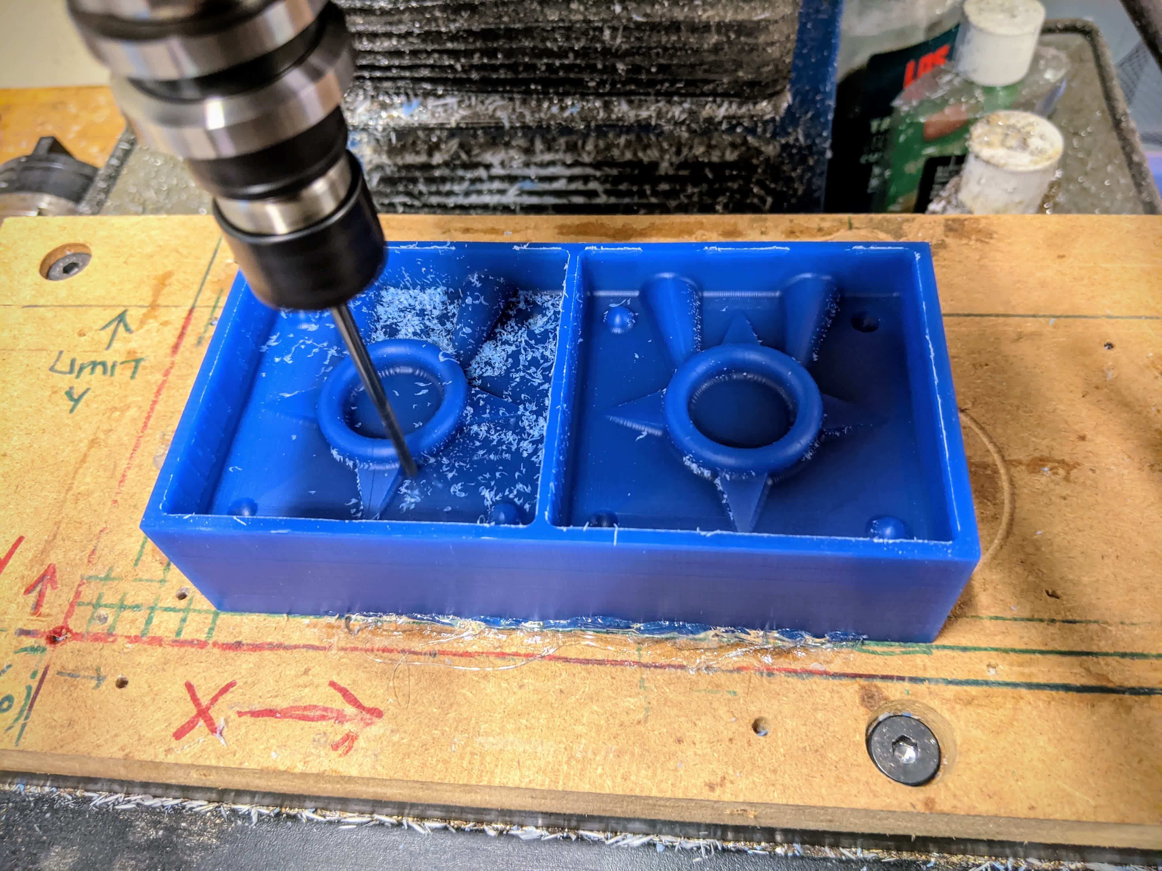
The left side shows the finished product after the rough cut. By now, I've replaced the tool with the 1/8" ball endmill and have started milling the surface finish.
Before this step, I actually lost my origin. When replacing the tools, I lifted the z-axis all the way. Apparently, the mill does not like that and asked me to rehome. Rehoming means I lost my origin. Lucking, I left a 1/16" of material on my stock, so it was not a fatal error to re-eyeball the origin, which I did.
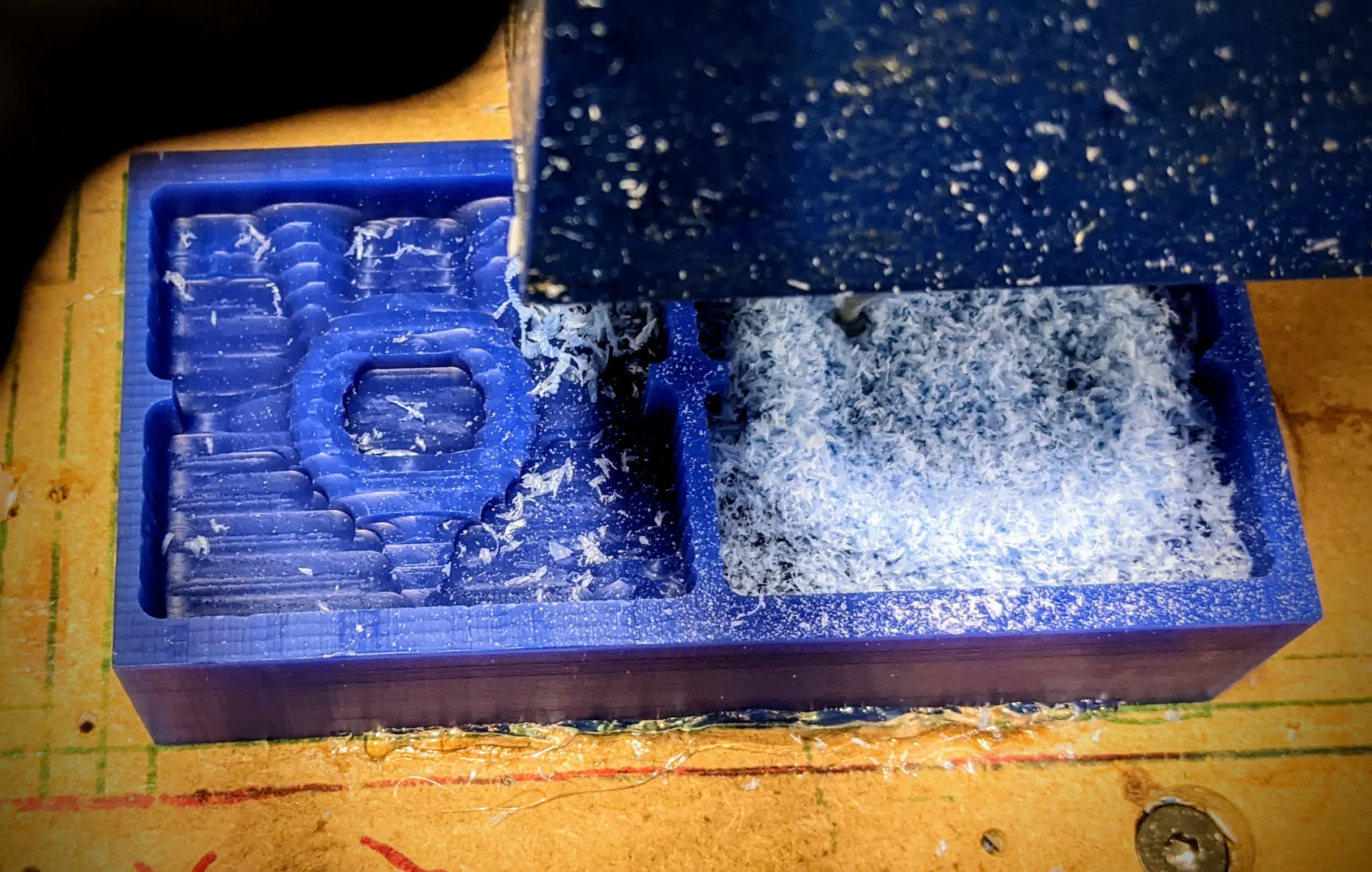
Here is an image of the surface finish cutting process. The chips are noticeably smalled than before given our smaller tool.
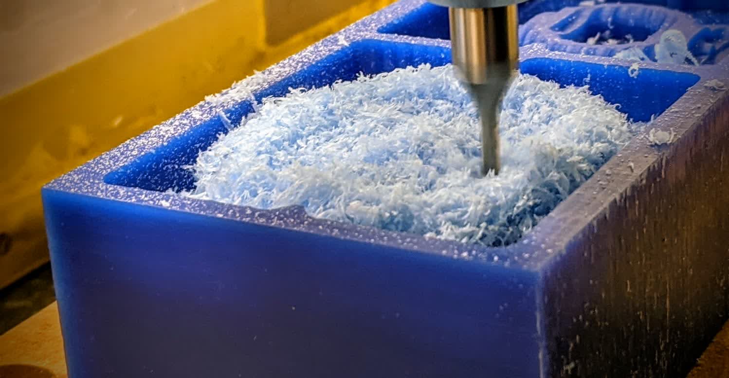
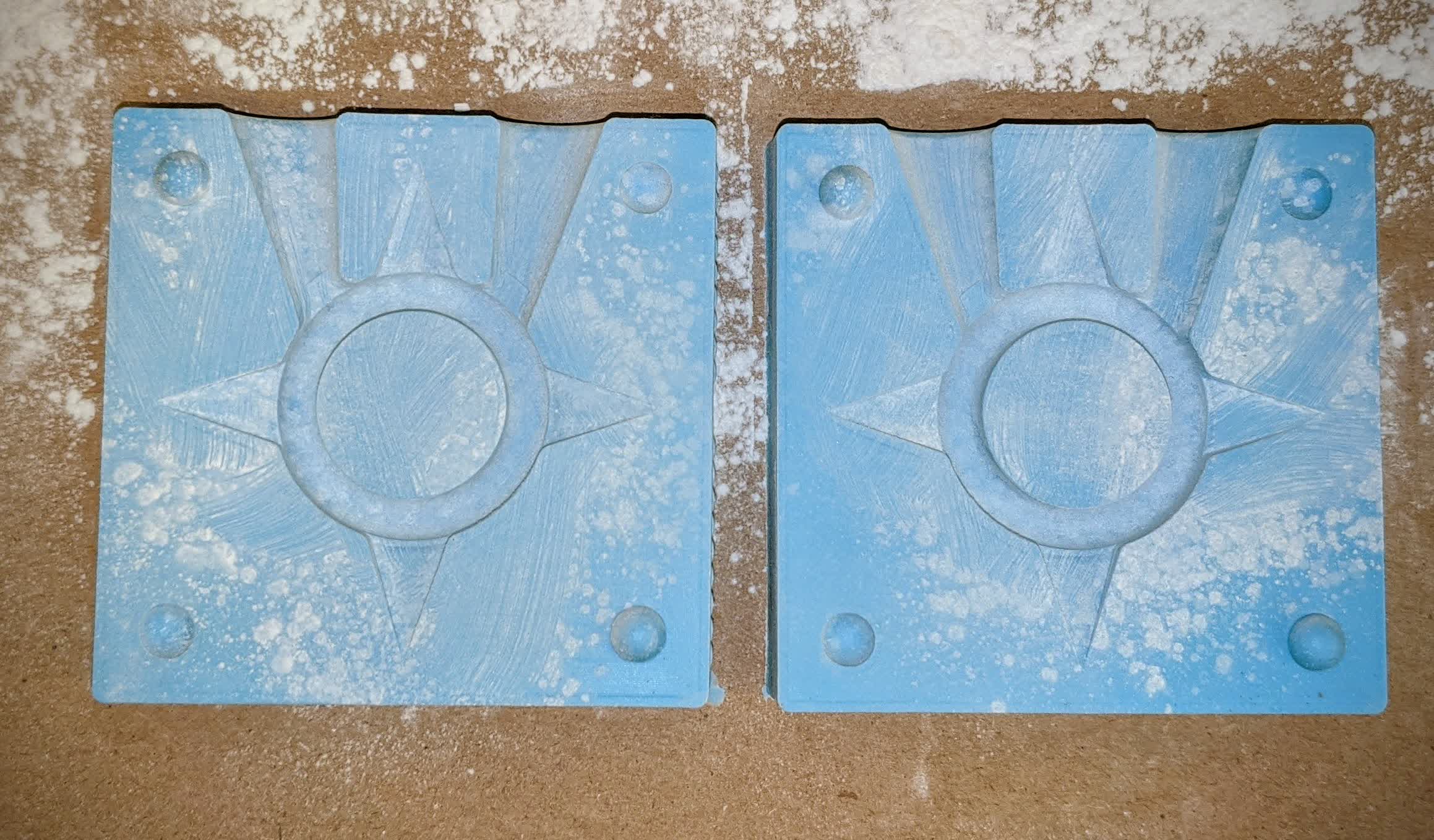
On the right, you can see the finished product after the surface finish. Things look very smooth, but we have filletted edges because we were using the ball end mill. At this point, I've replaced the previous tool with the 1/8" flat endmill and have begun the contour cutting to clean up and flatten these edges.
Here it is cleaning up the outside edges. It is not super important to clean up these edges; it is mostly for aesthetics.
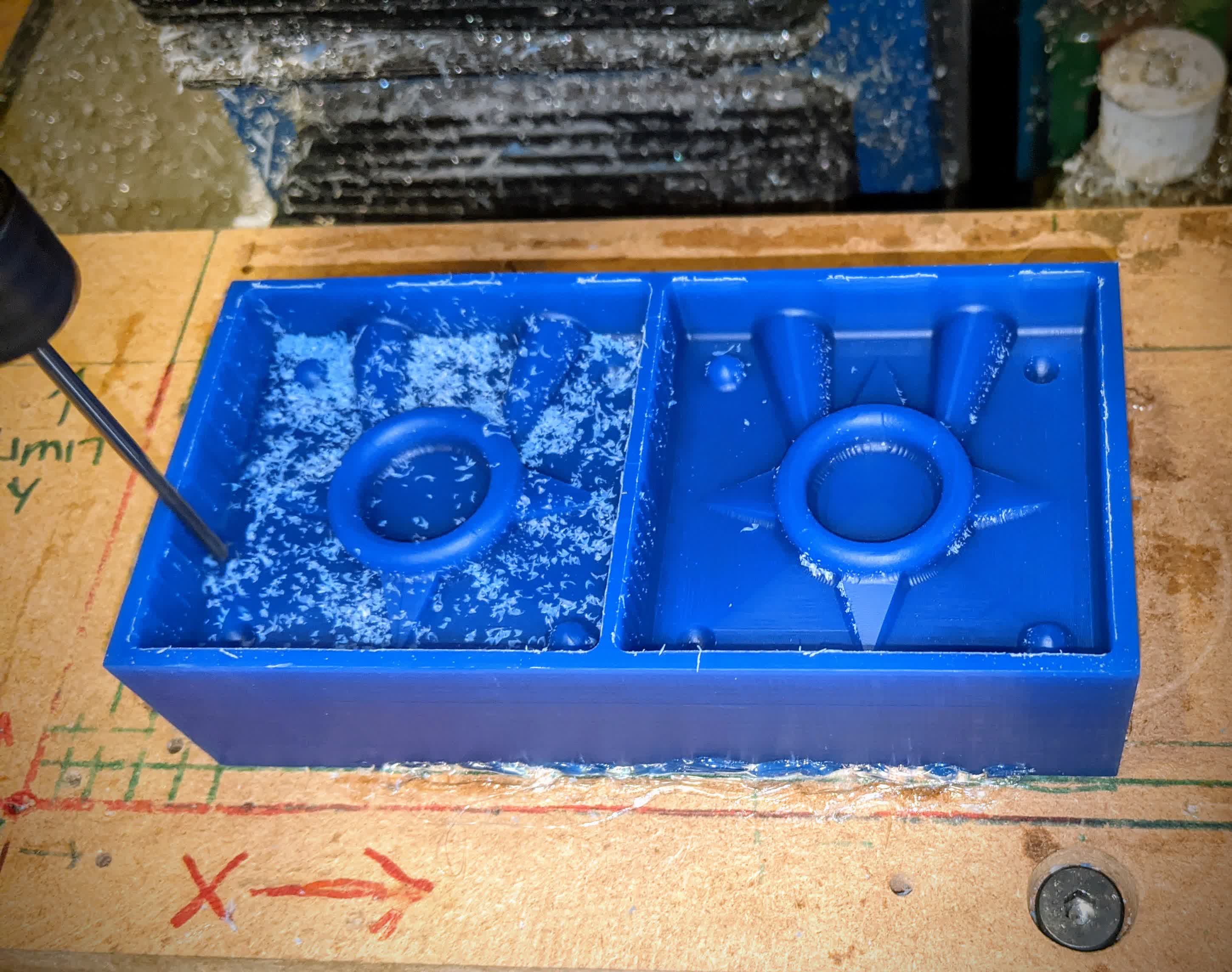
Here it is cleaning the outer edges of the shuriken:
and here the inner edge of the shuriken's ring:
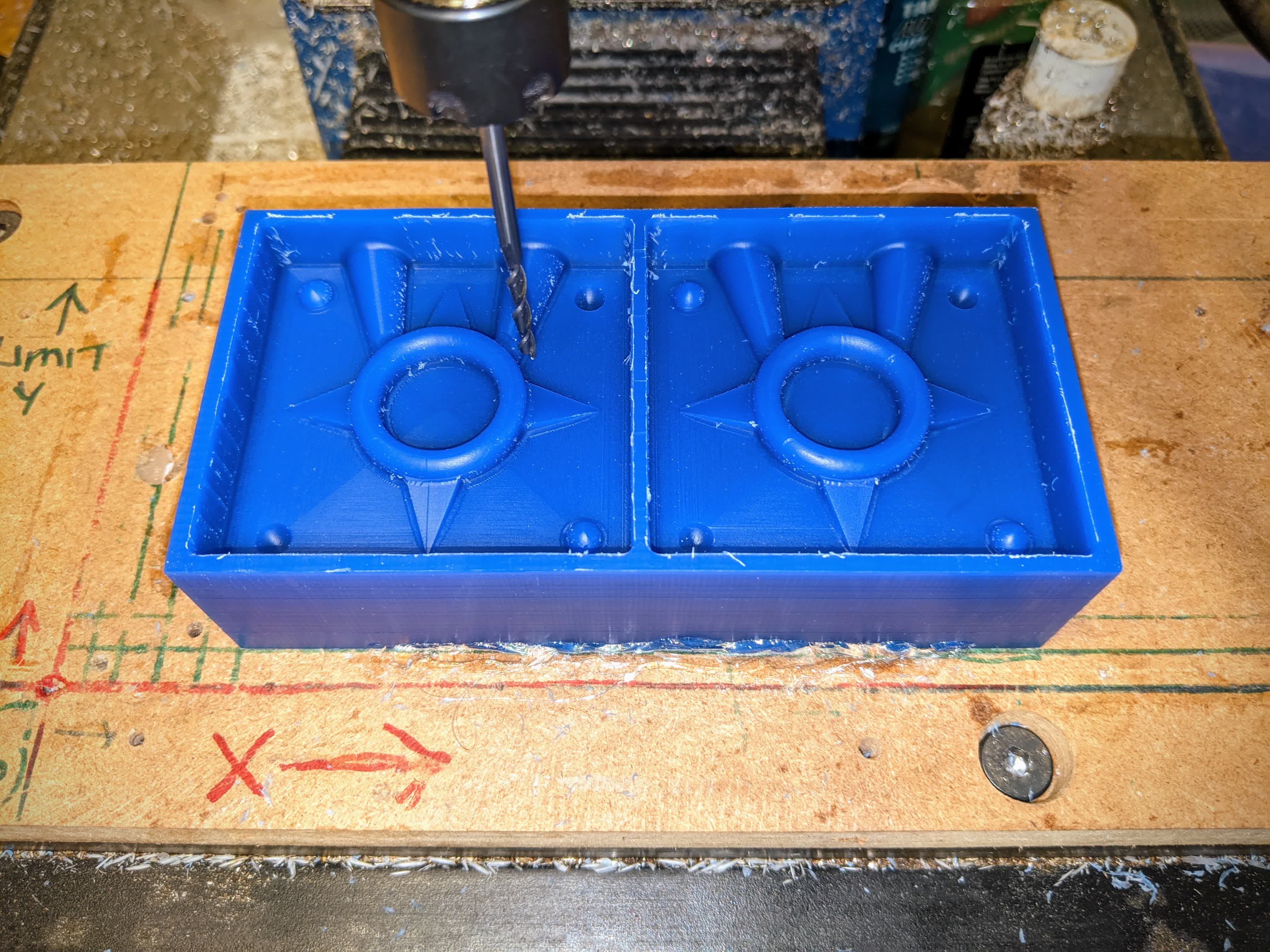
The rough cut, took about 20 minutes, the finishing cut took 2 hours(I made it go in very fine steps for a smooth surface), and the clean up cut took 10 minutes. It is done!
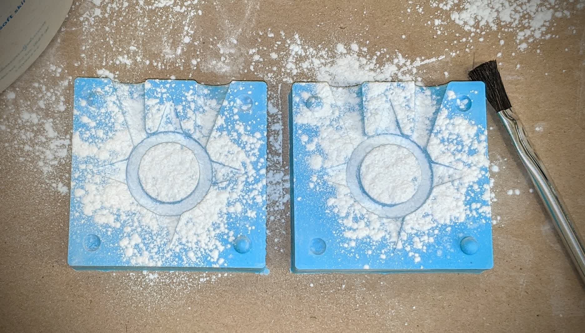
It was relatively easy to remove the glue from the outer edges of the wax. I just peeled it off with my fingers. Here's the wax right after taking out of the machine. You can see it has small debris that need to be removed.
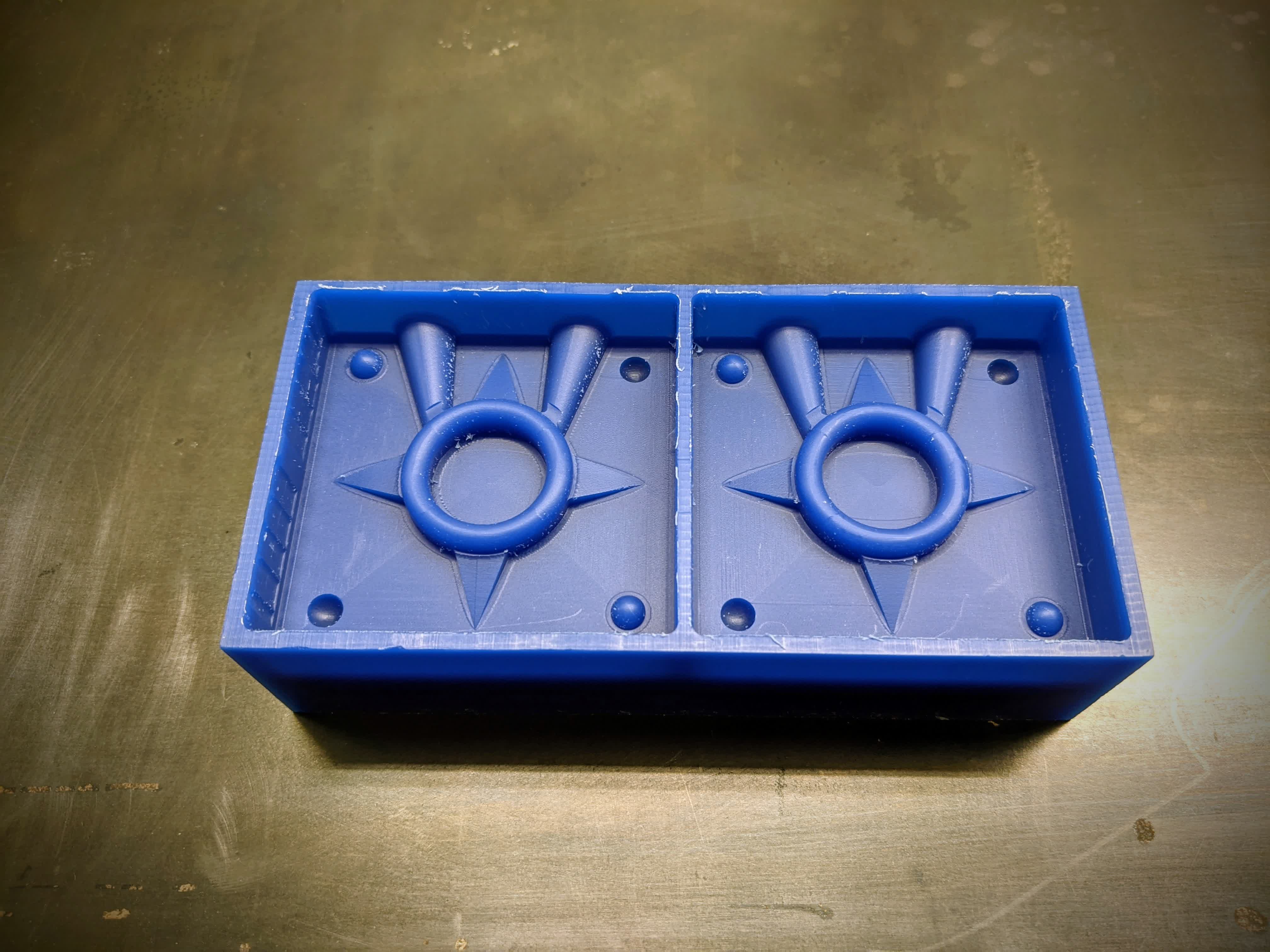
A fine brush can do the job!
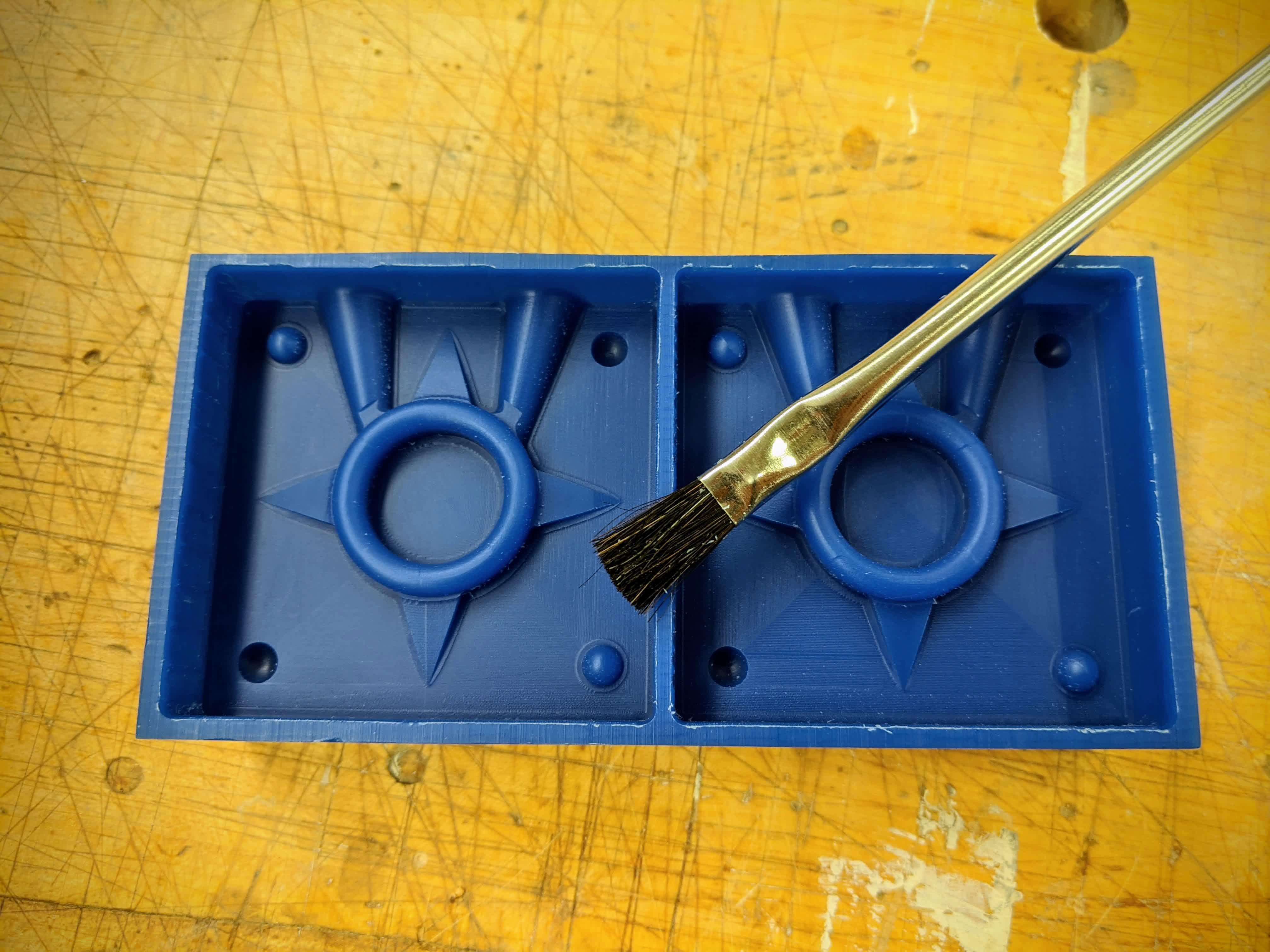
This ends the CNC'ing. I'd call that fairly smooth!
Casting Mold (Oomoo)
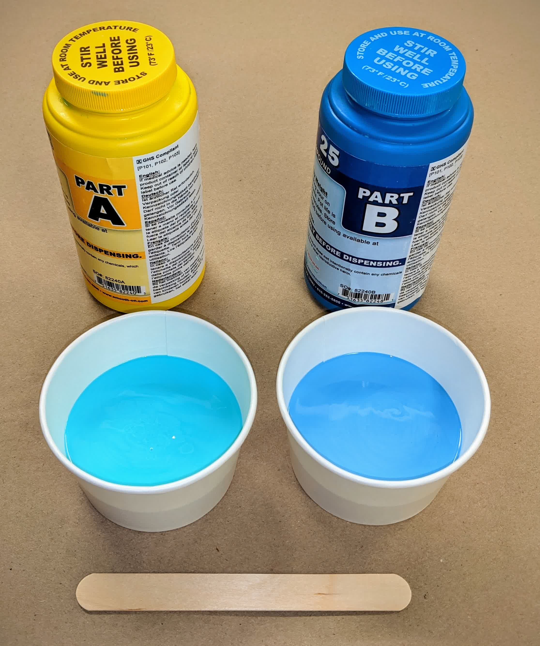
Next up is casting the Oomoo in the wax mold. Oomoo was a pretty easy to use material. We just need to mix equal quantities of Part A and Part B. I got 2 cups ready and a mixing stick. Also, don't forget to stir well before using as is writting on the top cap!
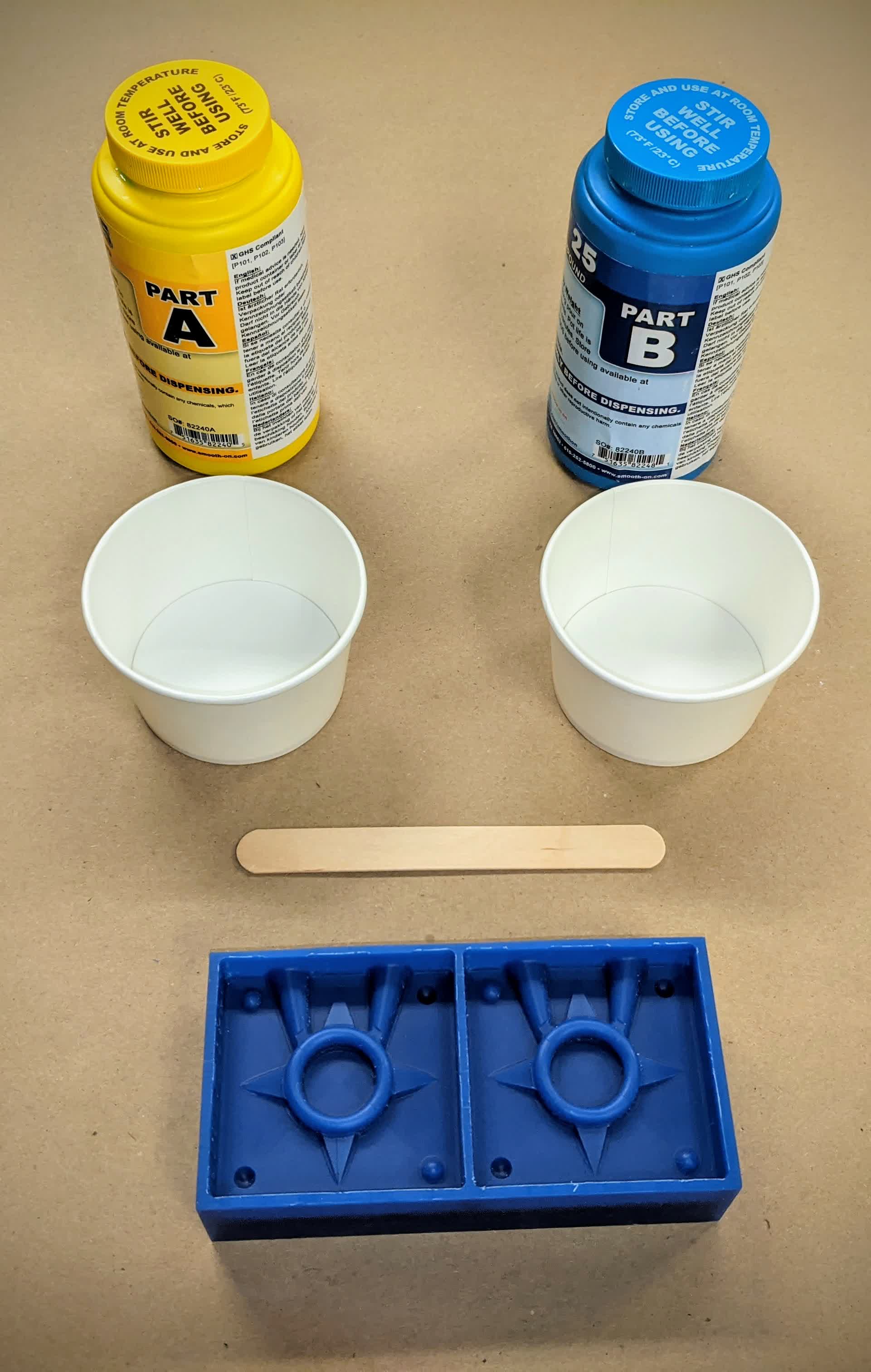
I eyeballed the equal quantities; I've been told Oomoo is pretty forgiving.
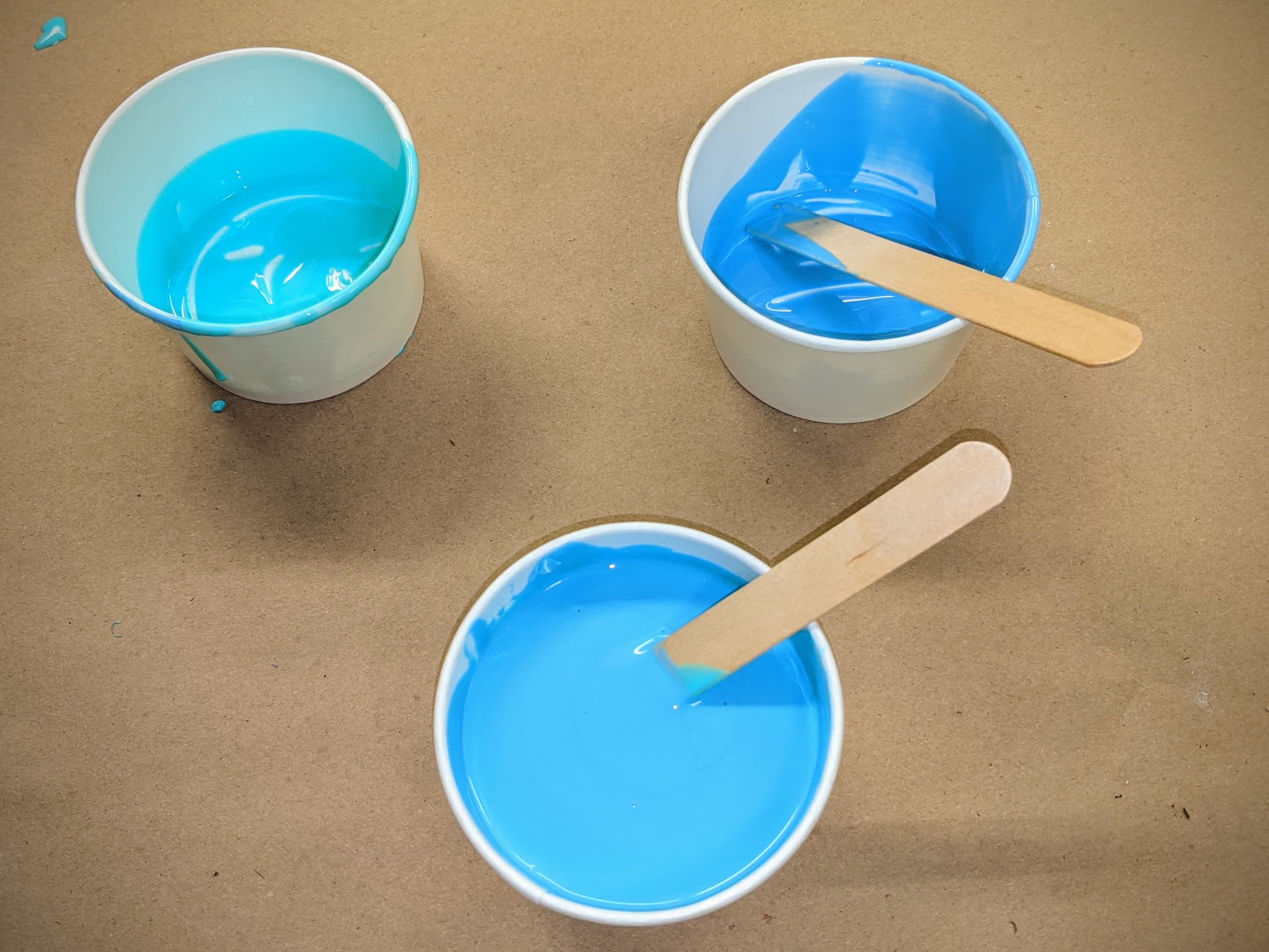
I poured the two parts into a third cup and spent a good 10 minutes mixing. Pro tip: don't forget to scrape the sides of the cup and bottom when mixing. Also don't spend too much time mixing. This stuff begins curing in 15 minutes!
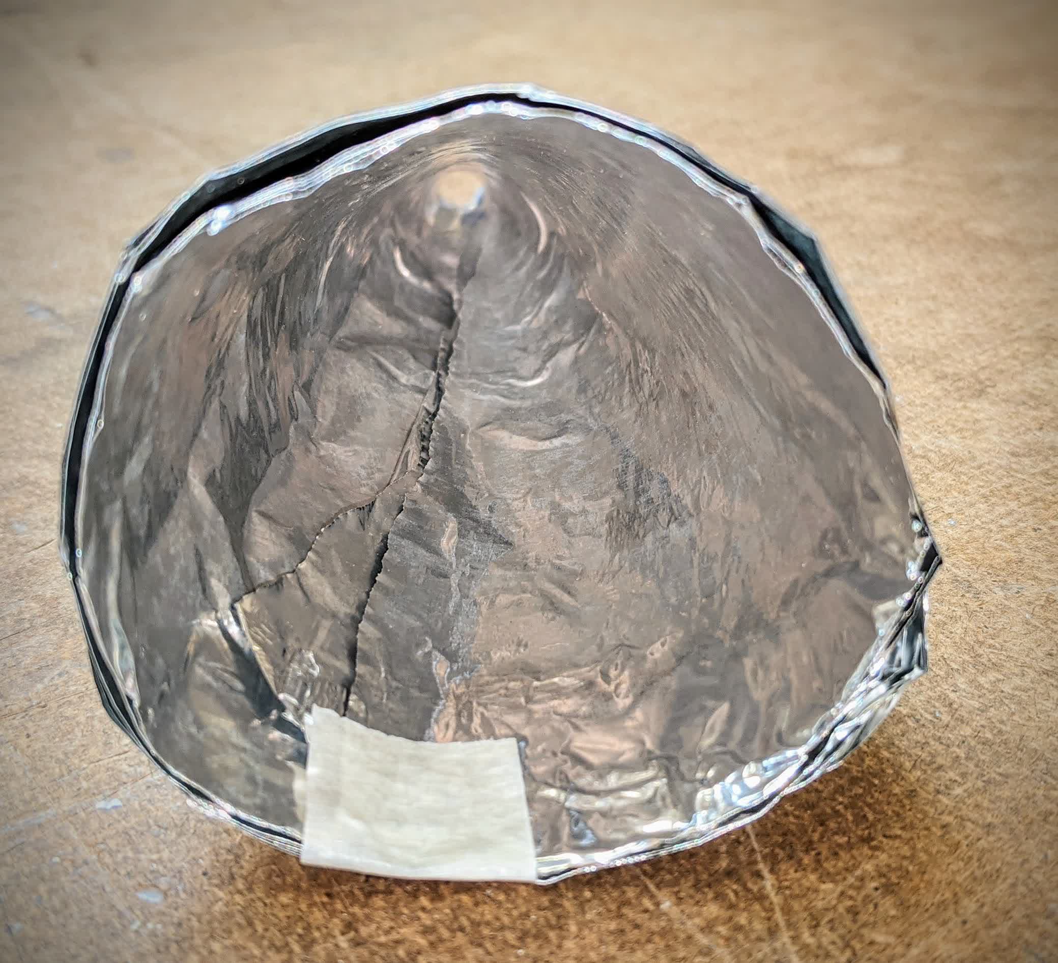
I poured the mixed Ooomoo into the wax mold very carefully to fill every tiny crevise. As you can see, we still have tiny air bubbles that need to be taken care of.
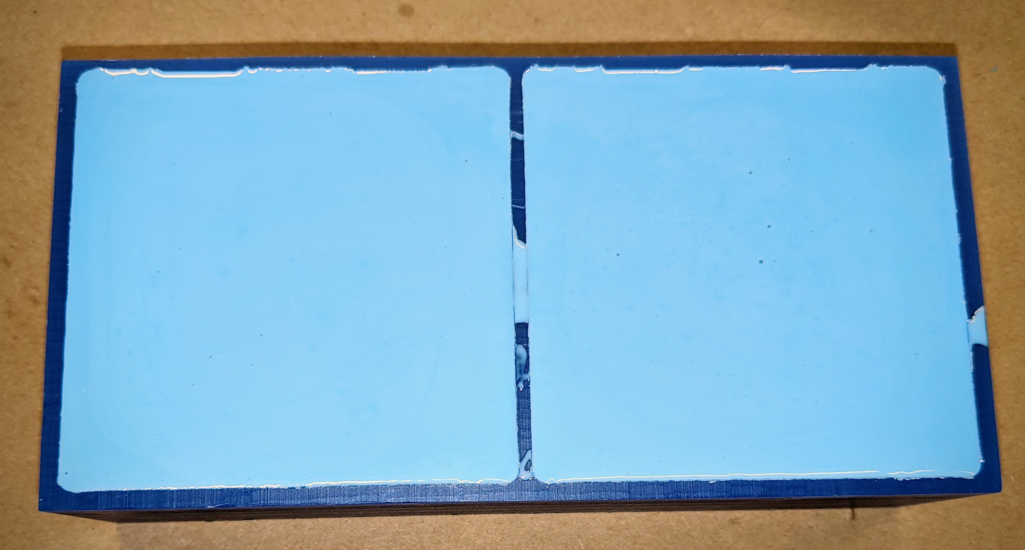
This is how you deal with air bubbles:
After a good 5-10 minutes of tapping, this is the final product:
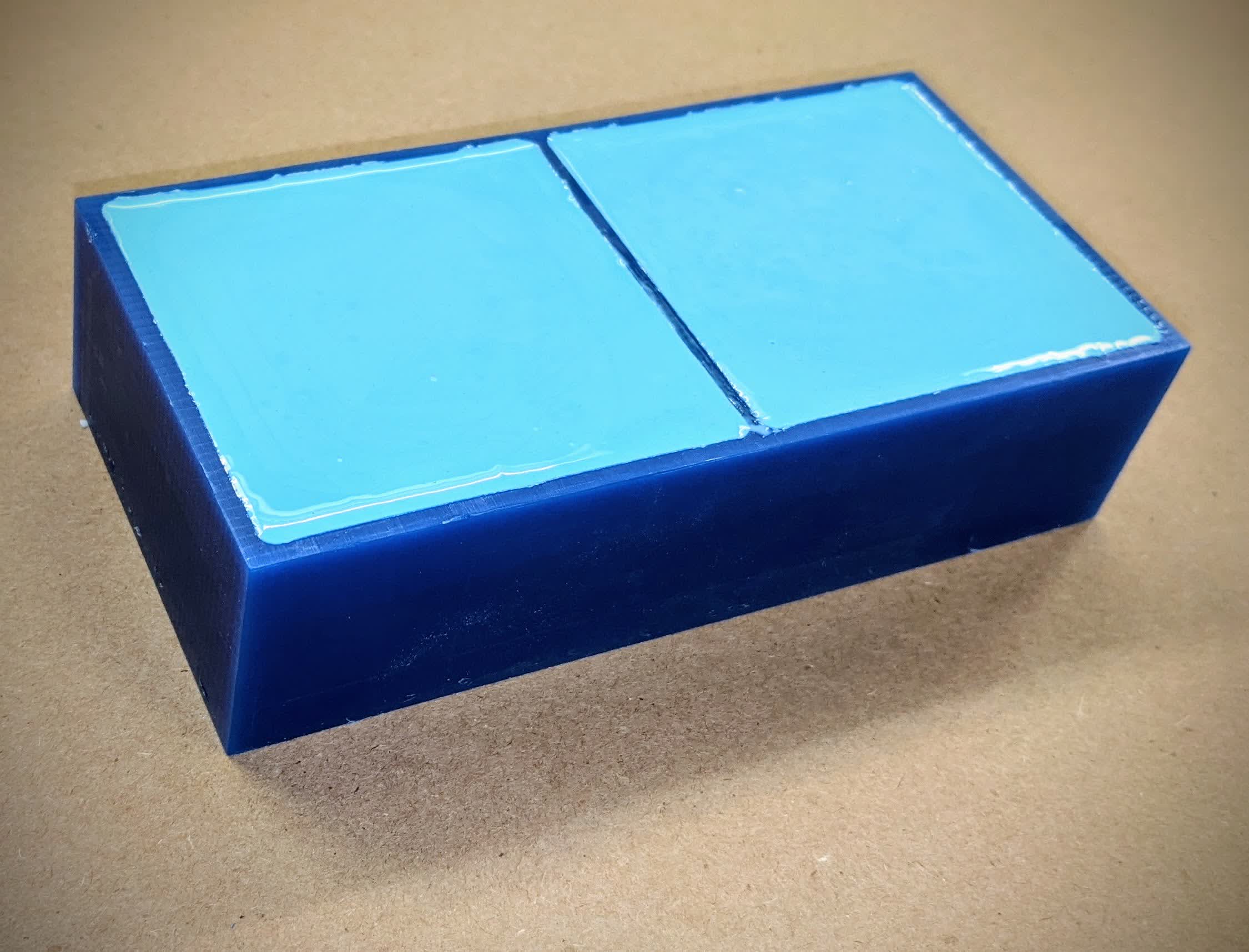
I let that sit over night, though it only needs 75 minutes to fully cure.
I then removed the Oomoo the next day by using the scraper below against one of the edges and applying pressure while pulling up until the cured Ooomoo came out.
This is a very critical step as the Oomoo can easily crack under too much pressure.
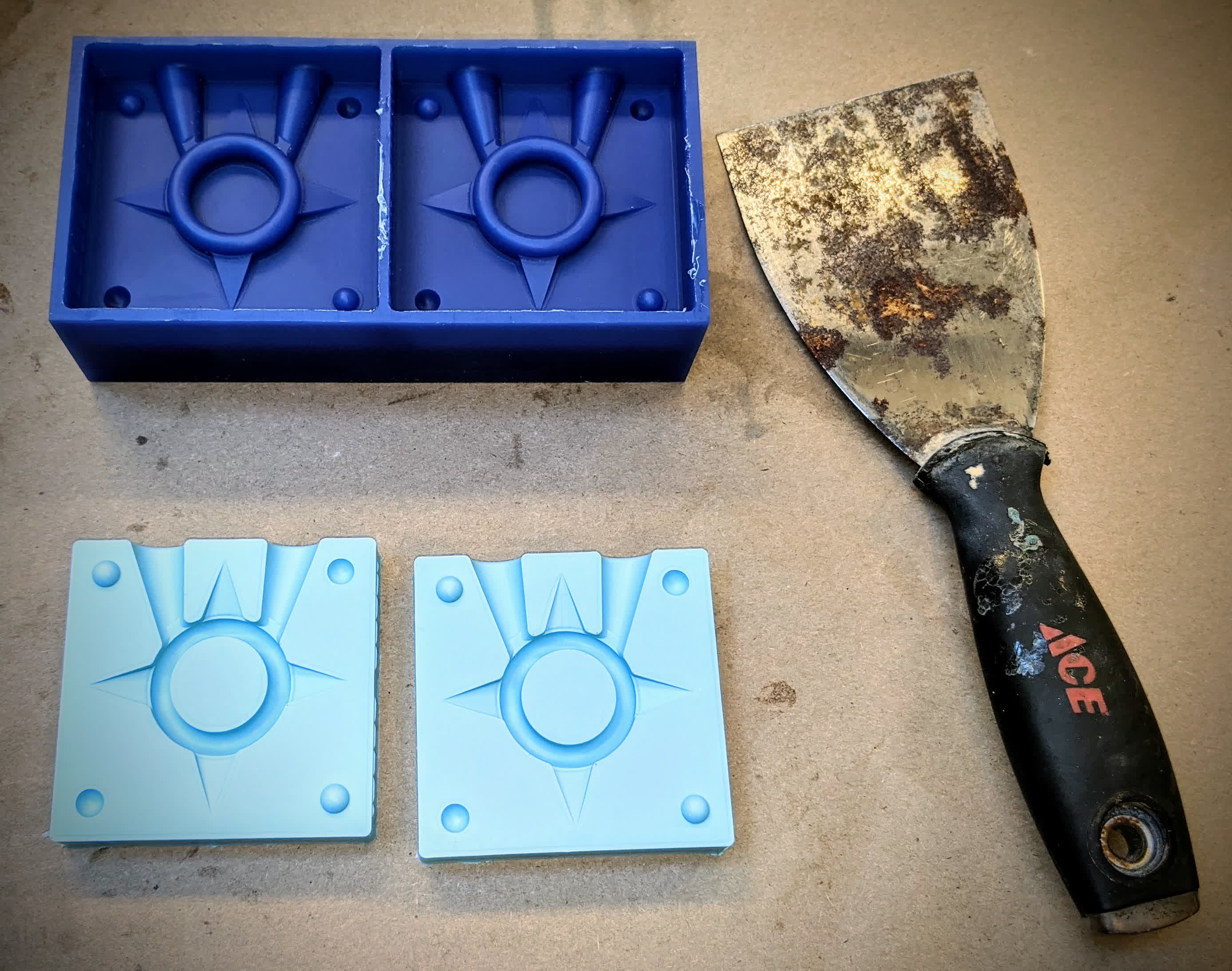
My Oomoo mold is done and ready to be used to cast my part!!
Casting Part (Roto281F)
Since I am using molten metal to cast my part, it is a good idea to sprinkle some talc (baby powder) on the interior of the mold. This reduces the surface tension of the Oomoo mold with the viscous molten metal.
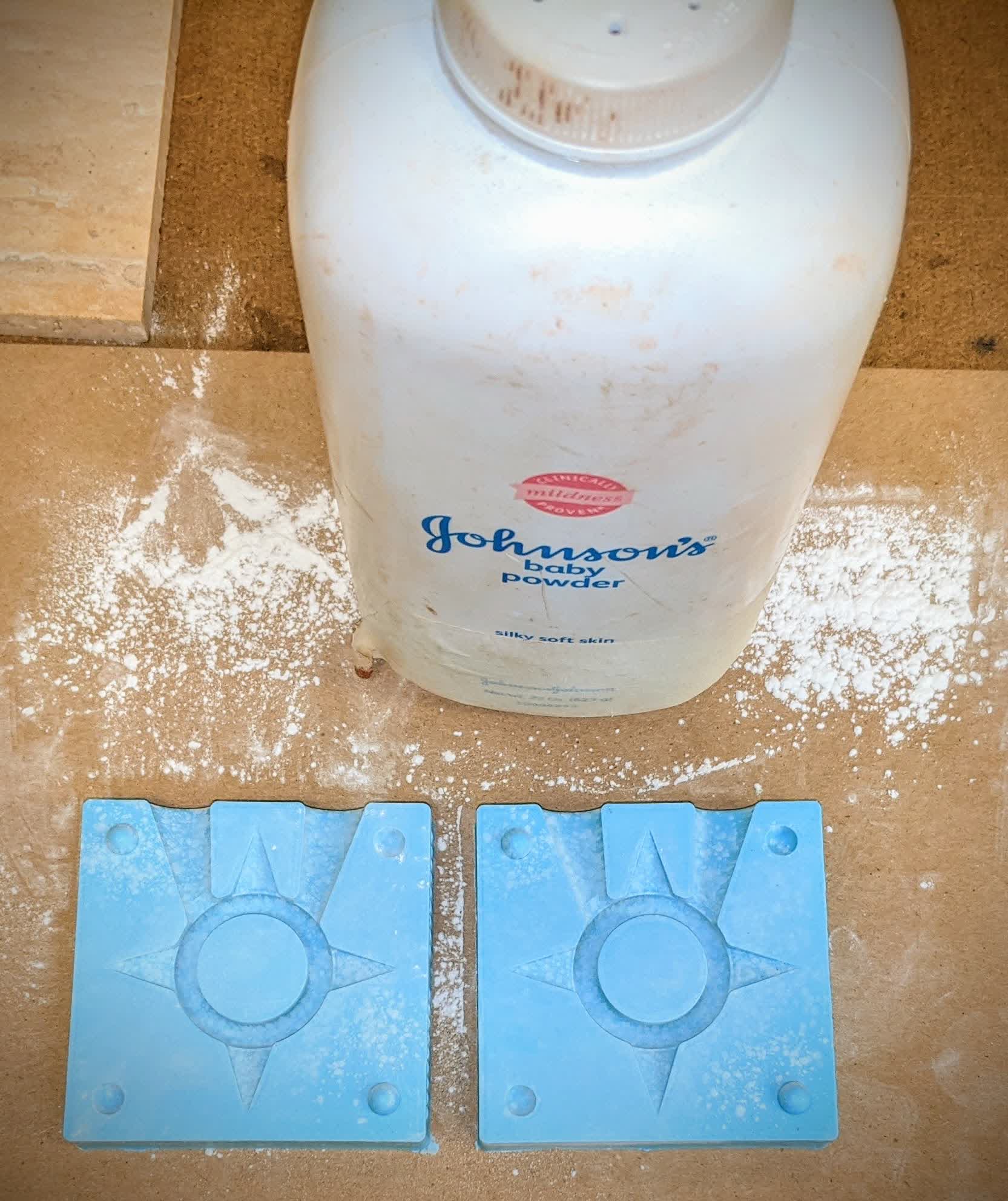
Sprinkle generously:
I used a fine bursh to make sure the walls where my part will be in contact with the molten metal are properly coated.
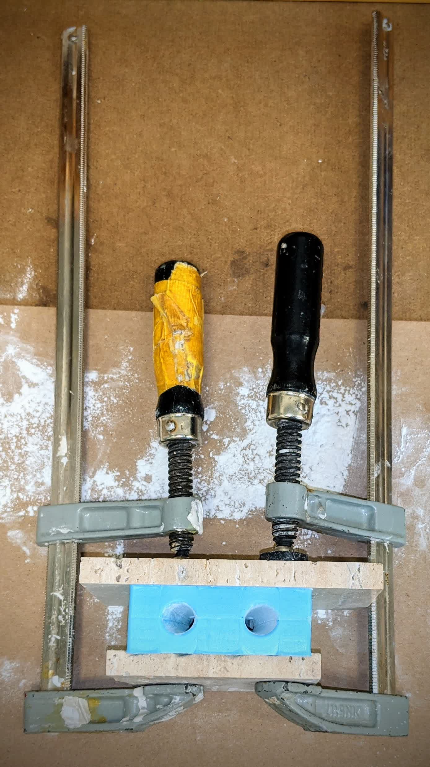
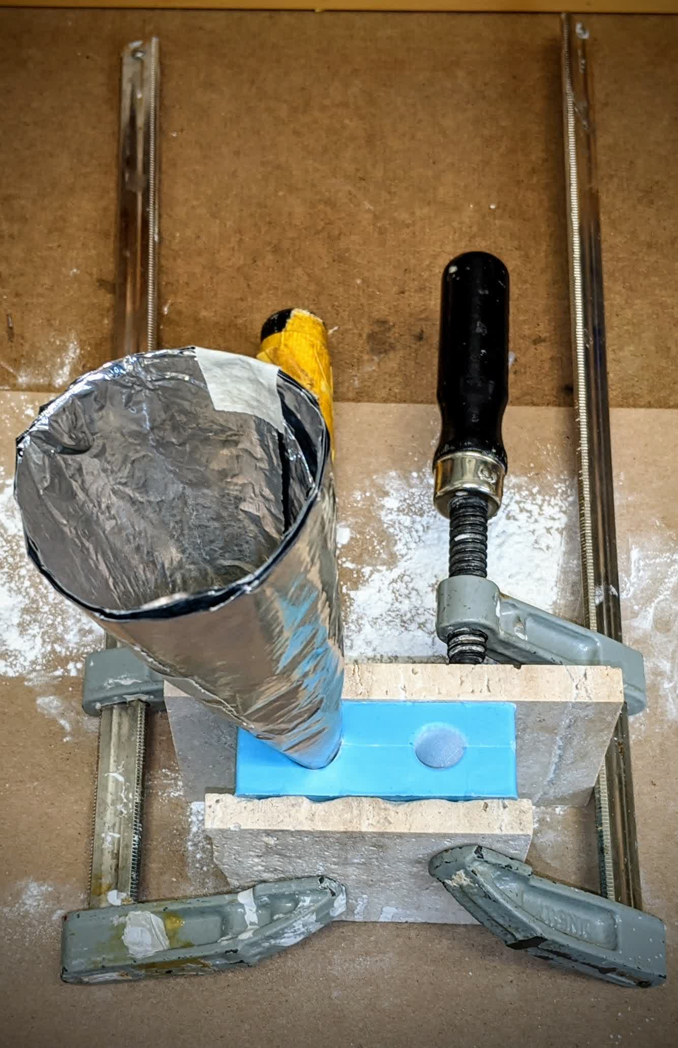
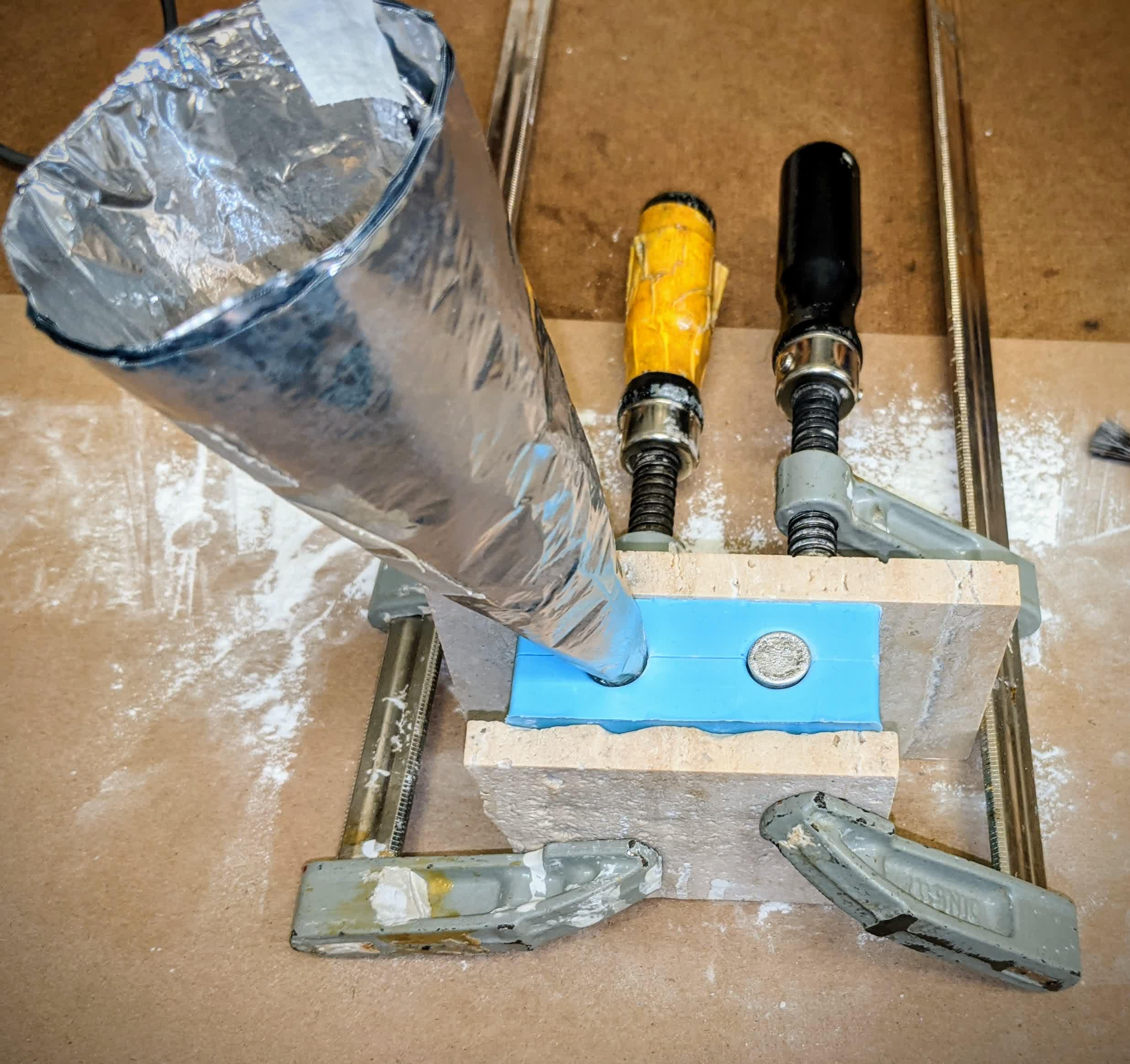
Next, I sandwiched my 2 Oomoo parts between 2 hard plates (don't know what they are or where they come from, just found them lying around), and clamped.
Because Ooomoo is so compliant, it is important to apply enough clamping force to hold everything together, but not enough to deform the Oomoo. Otherwise, you'll restrict the flow path of your casting material.
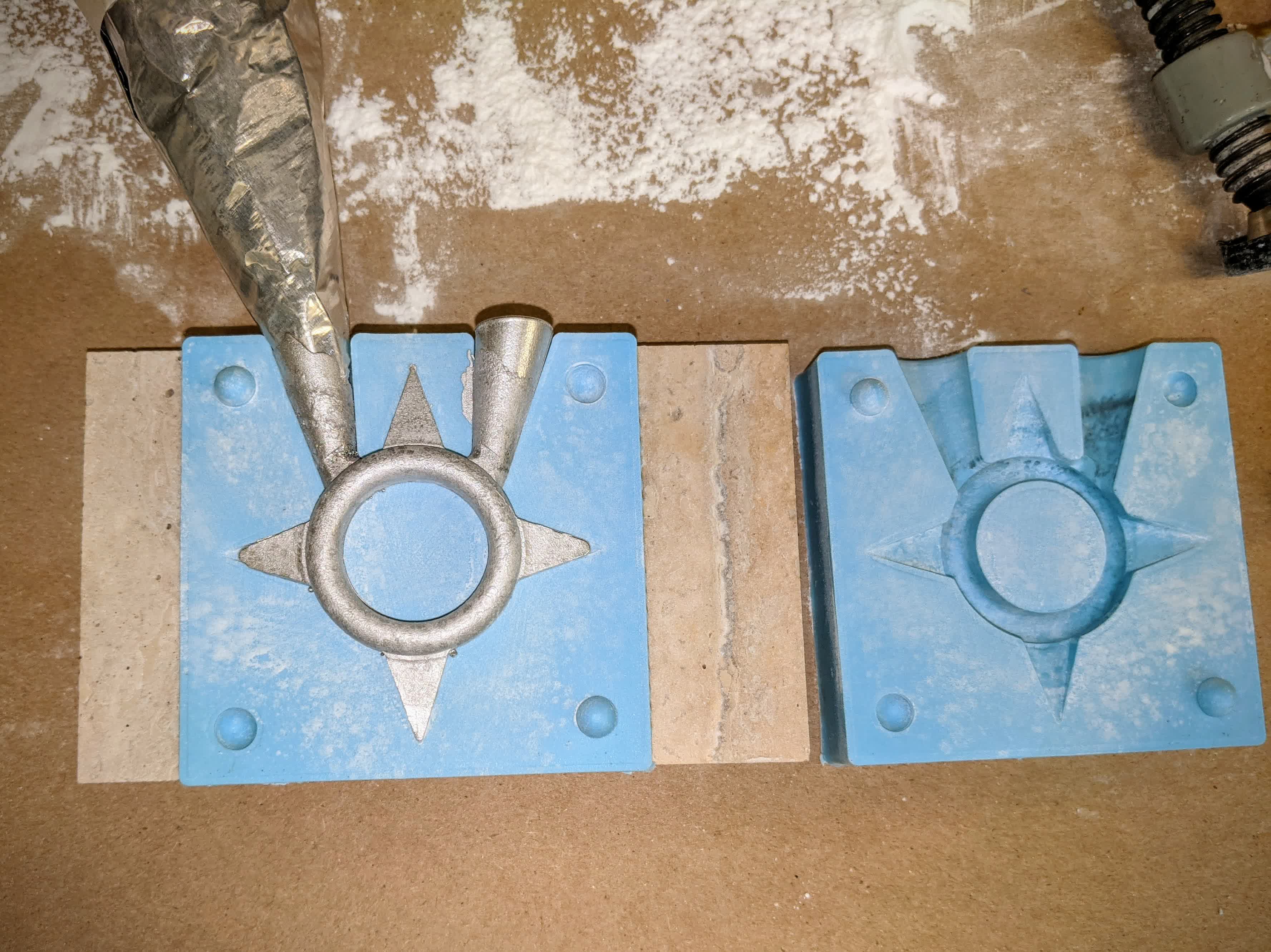
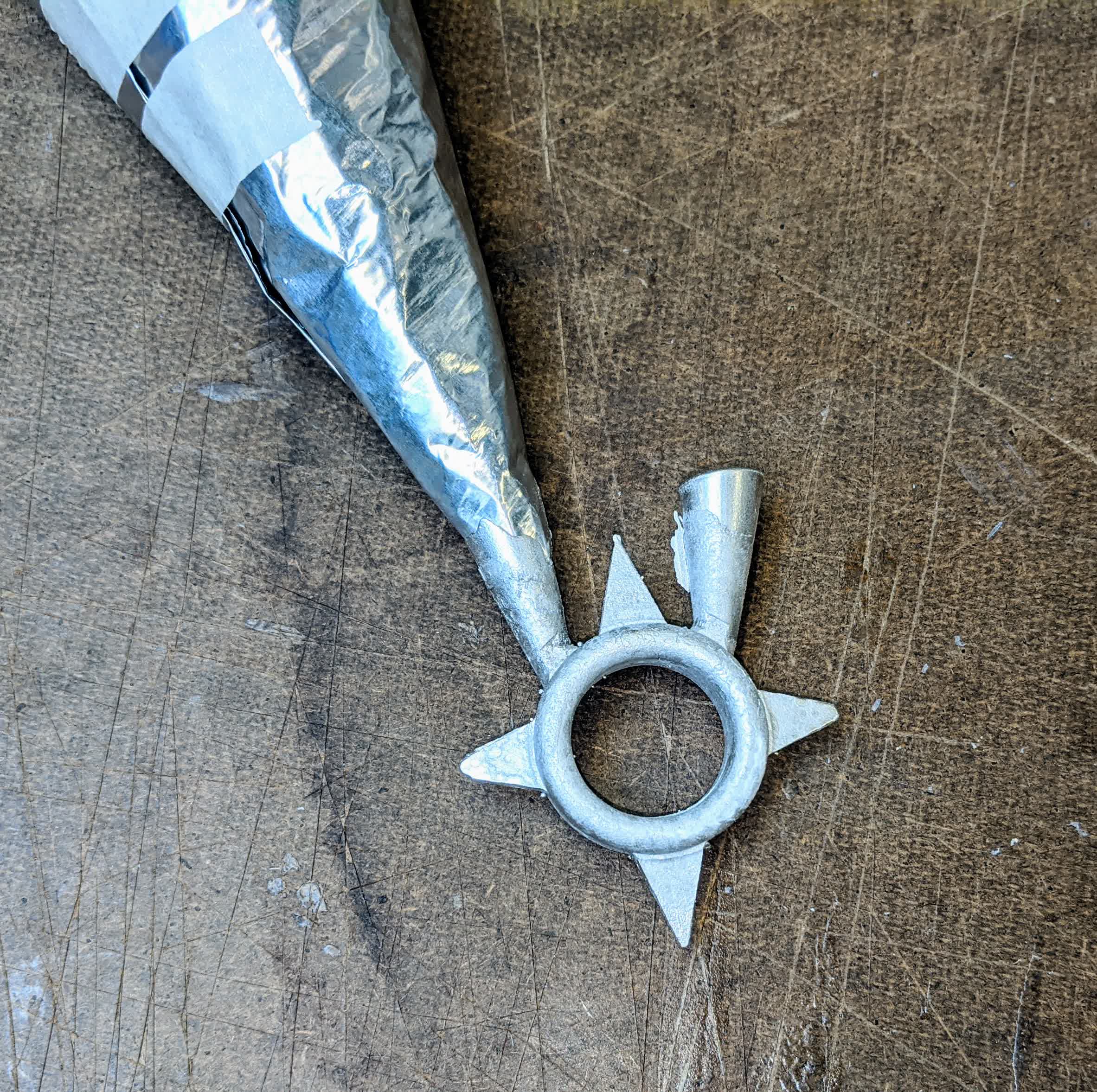
I also found some aluminum foil and decided to make a makeshift funnel. Aluminum has a higher melting point than the metal I am using to cast my part, and it worked out perfectly giving me a bigger pour hole to use.
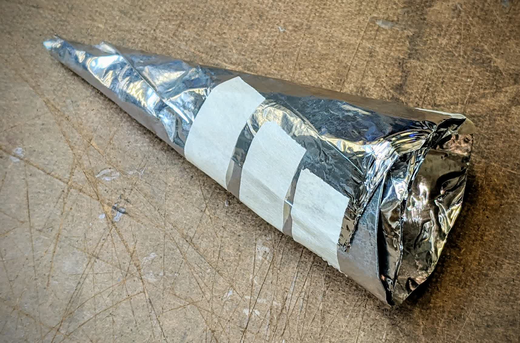
The bottom of my cone was small enough to fit into the pour hole on my Oomoo, but large enough not to restrict flow (~1/4").
I then secured the cone into one of the pour holes by rotating while pushing in. I definitely did not want it to fly out while pouring molten metal.
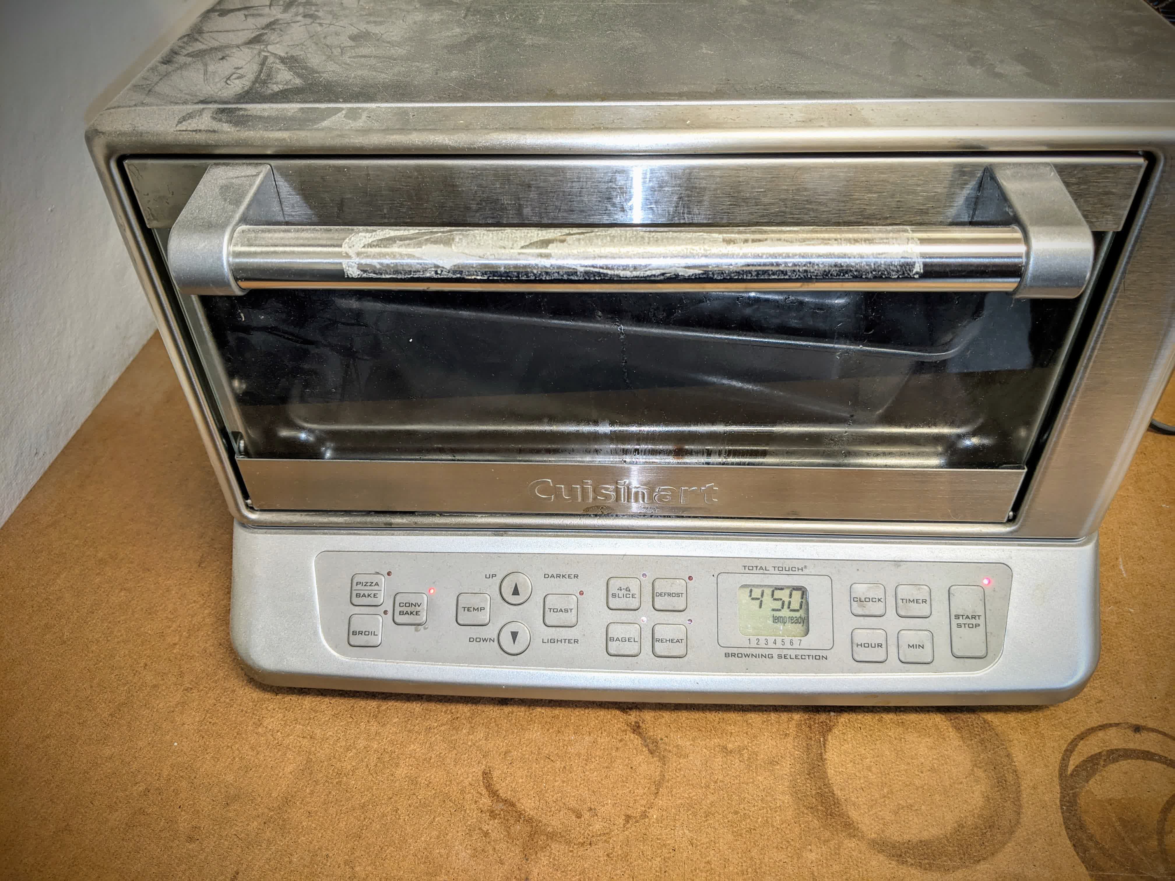
With my mold ready, it was time to prepare the casting material. I used a toaster oven set on convection baking mode at 450 degrees F. The material I used was Roto281F. This is a low melt fusible bismuth based alloy (58% Bismuth and 42% Tin) ingot.
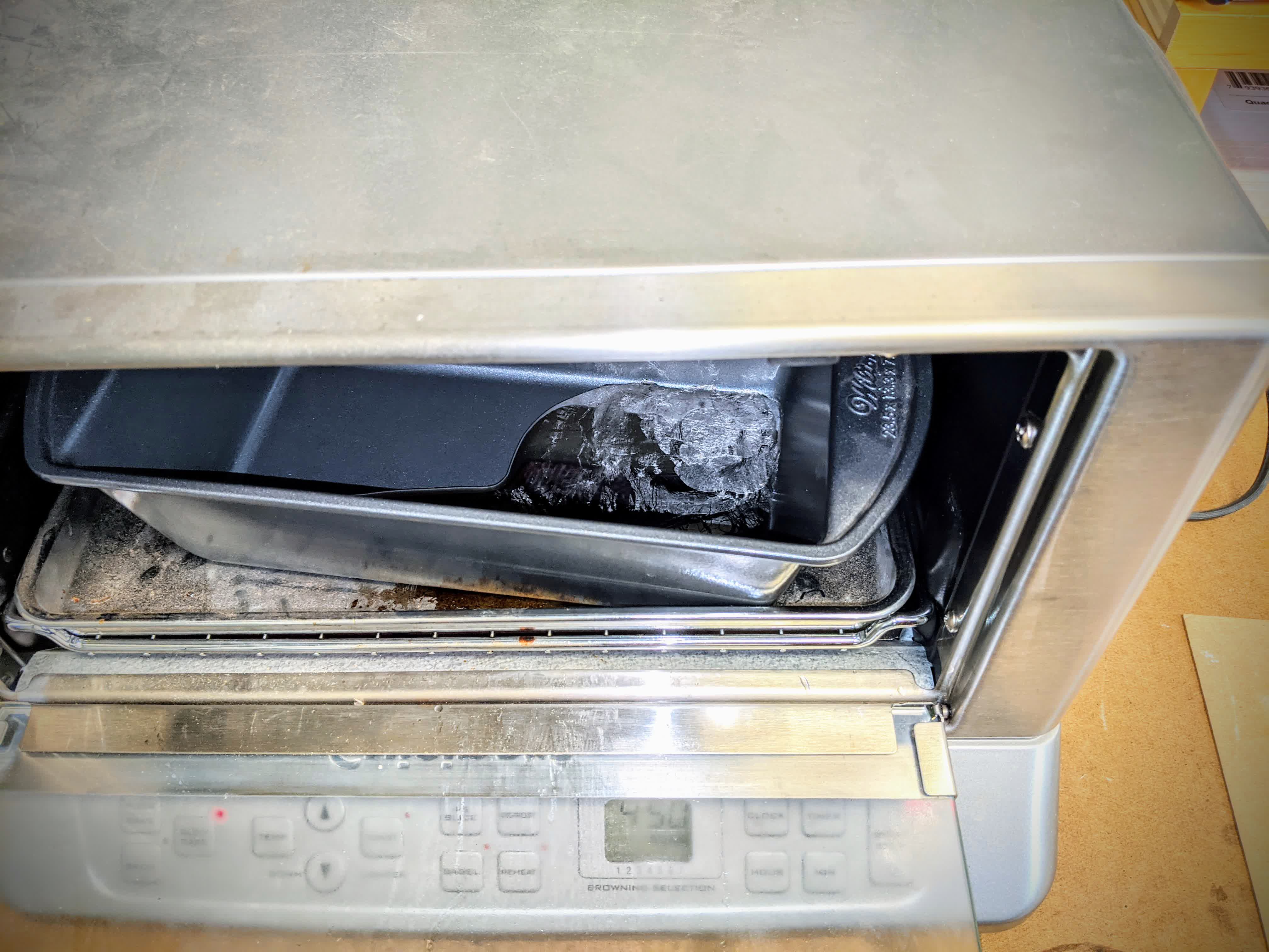
If you look closely, you can see it in there:
Here we see the ingot fully melted.
Now came the critical step of pouring it in. I unfortunately made a mistake here. I thought it would be a good idea to pour a little at a time, and tap the mold against the table in between pours. That was not a good idea because it loosened the hold of the clamps on my mold. I did fill it up though until the molten alloy came out the other sprue.
Here is what it looked like when I opened my mold. I was very worried that the top blade would not fill all the way and was hoping the hydrostatic pressure created by the column in the aluminum cone would help. It looks like it did as it came out perfectly. unfortunately, I did not forses that the side blades would be blunded like that, but that's life. You live and your learn.
I then took the part out of the mold after 10-15 minutes to cool off.
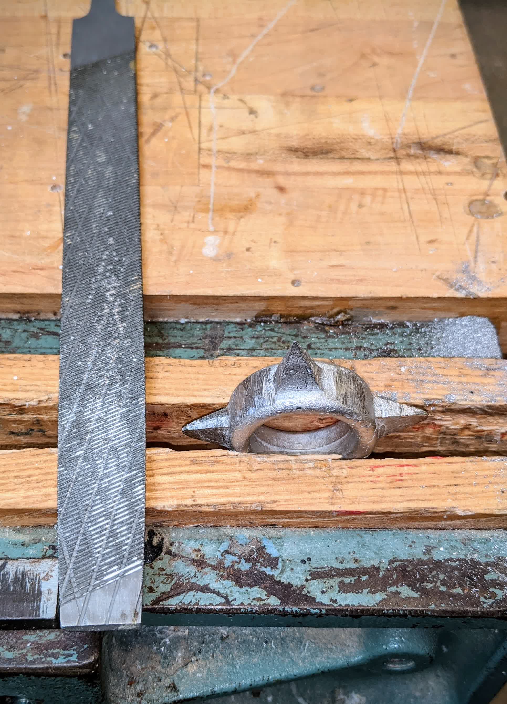
I used a hack saw to cut off the sprues.
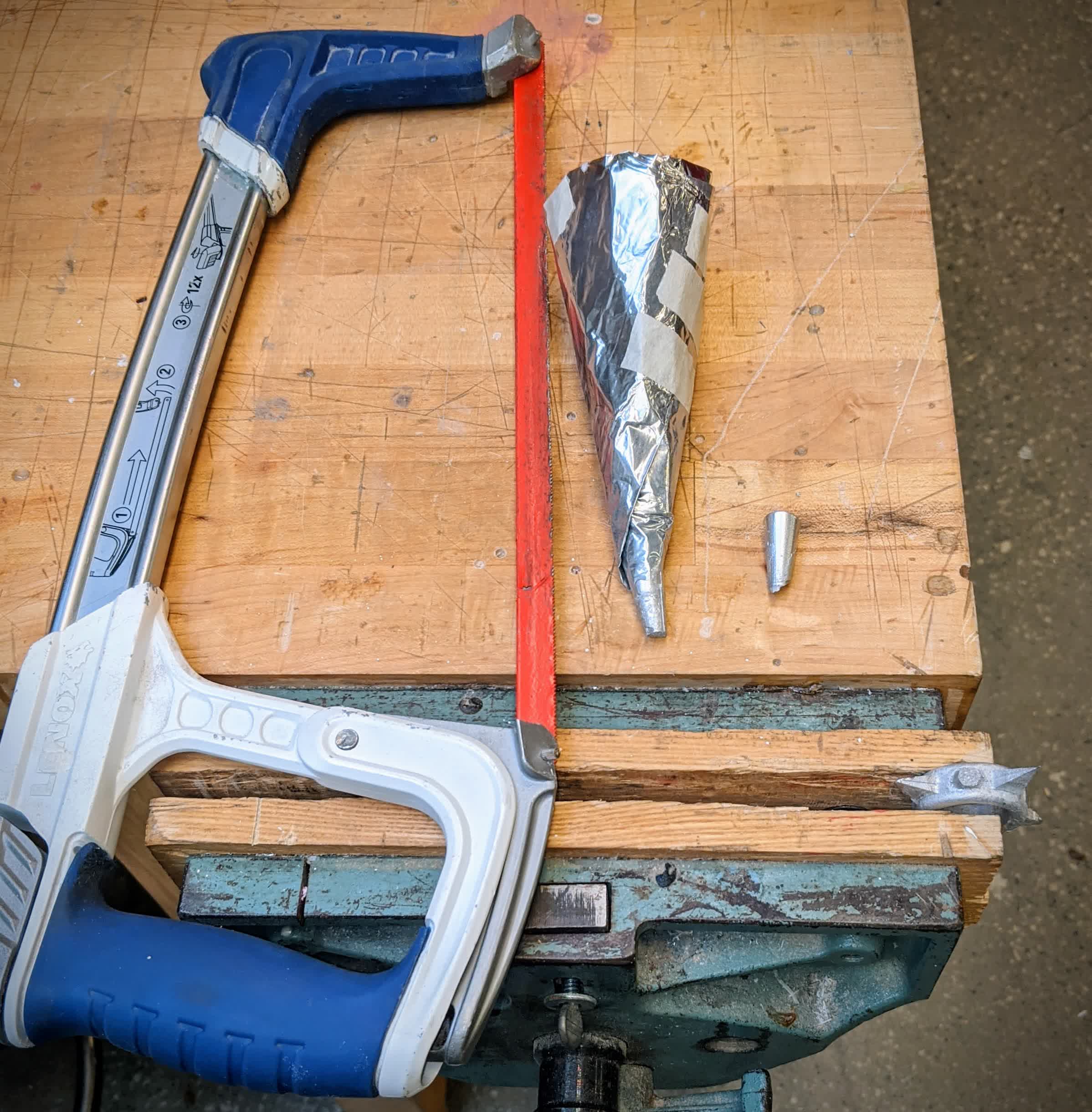
Then I used a file to clean up the cut surface. This material is fairly weak and was easy to cut and file.
This is the final product. My very own small, non-functional, decorative, rotate in my fingers when I'm bored, shuriken:
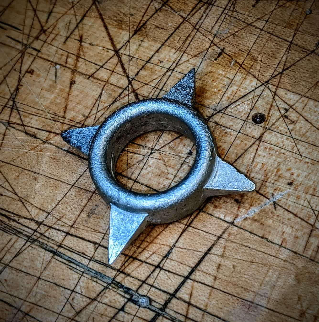
Does this officially make me a ninja??
Files:
Shuriken CAD Fusion 360 file
Shuriken STEP file
Shuriken surfaces Rhino file
Extra intersection curves Rhino file
MasterCam toolpath file