Web Design, Version Control, and Final Project Brainstorm
Laser & Vinyl Cutting
3D Scanning and Printing
Make Something Big
Molding and Casting
Electronics Production
Electronics Design
Embedded Programming
Input Devices
Output Devices
Networking & Communications
Interface and Application Programming
Final Project
Group Assignment
The group assignment was to test the CNC mill. This was done in collaboration with with Jordan, Maya, Gil, and Emma. The process and results can be viewed here.Assignment: Make (deisgn+mill+assemble) something big.
Make Something BIG - CNC Machining
Design
For my "make something big" assignment, I wanted to make a bookcase that doubles as a bench. Here is what my daughter's bookcase looked like: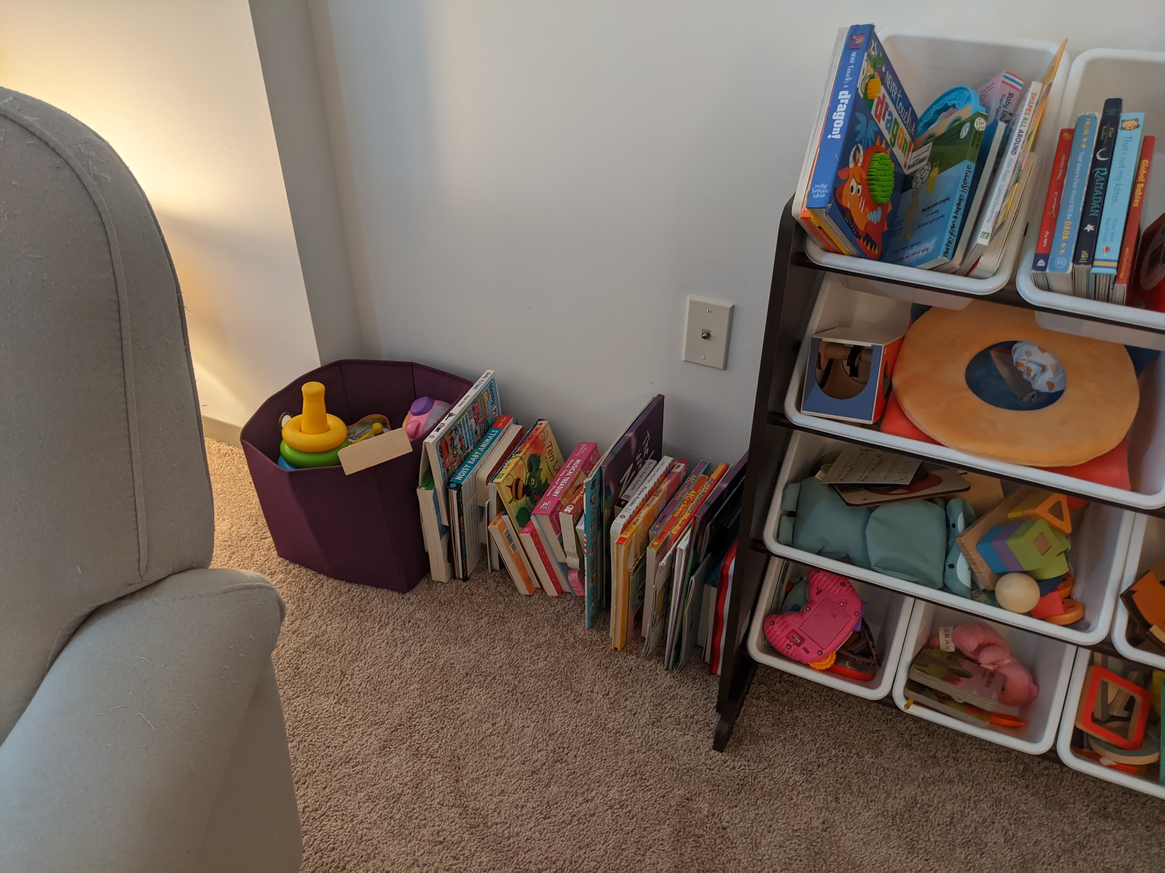
It took me a while, but here is the design I came up with:
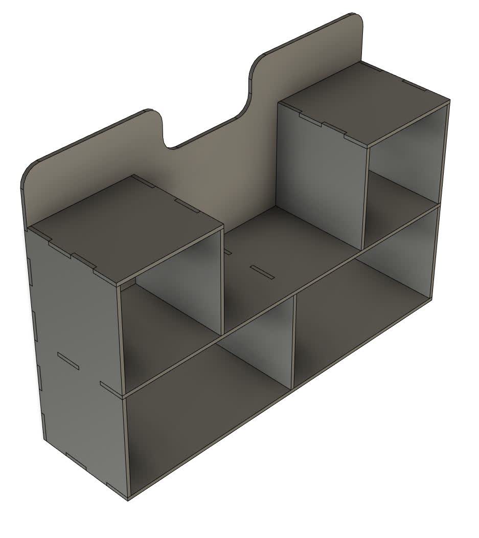
It is a pure press-fit design, but it should work just fine. The design is fully paramteric, because we will be cutting this out of OSB. OSB is a pretty bad material because it is basically left over woodchips glued together. This means that it is highly porous and variable in thickness, even along the same board. It can also change in thickness depending on the day, due to factors like humidity and temperature. On the day of cutting, I measured the thickness of my board to be 0.455", and adjusted my slot thickness accordingly.
The sheet of OSB we have is 8ft long and 4ft wide, so it is important that I make sure all the parts fit. Fusion 360 has an amazing auto arrange feature that does this automatically. The design was done in the "Design" workspace, but the arrange feature is in the "Manufacture" workspace. Once there, I created a manufacturing model, which is a copy of the design model, and making any changes to the design (like changing thickness), will be reflected in the manufacturing model. However, any changes made in the manufacture model (like breaking up and the components, moving them around, and arranging them) will not change the design model. I simply draw an 8ft x 4 ft rectangle simulating the OSB sheet, and specify it as the arrange plane. I even specify the distance of any given part from the borders as well as the spacing between parts. I set both of these to 1".
Note, I did not realize this immediately, but the design needs to be broken up into components, or else it will take the whole thing and throw it on the sheet. Luckily, I could easily right click on the bodies and turn them into components by right clicking on them and selecting the "create component from body" option.
Here is what I got after doing all this:
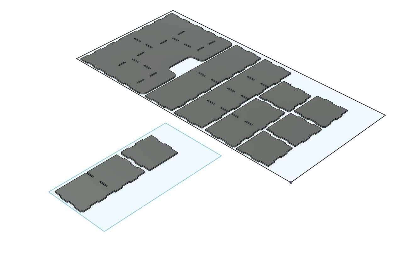
As you can see, all the parts do not fit. Luckily, there was an extra 2 ft x 4 ft sheet of OSB leftover from the group assignment that I used after checking in with my group.
CNC
The next step is programming the CNC toolpath. I did this with the help of Zain, one of the TA's. He imported the dxf of my arrangement into Rhino, and using Grasshopper set points at all the interior corners and at the interior slot cutout corners. In addition, the points were set to 3 layers:1-points corresponding to the interior slot corners
2-points corresponding to interior corners on the exterior of each part (like the inside corners of the press-fit box joints)
3-points corresponding to the exterior corners
This was then imported into MasterCap to designate the tools and their respective paths.
Here is the list of tools we set for the job:
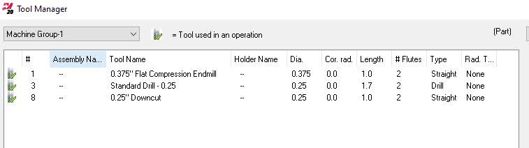
The 1/4" drill was designated to drill the holes. The 1/4" downcut endmill was used to cutout the slot interiors. The 3/8" flat compression endmill was used to cut out the exteriors.
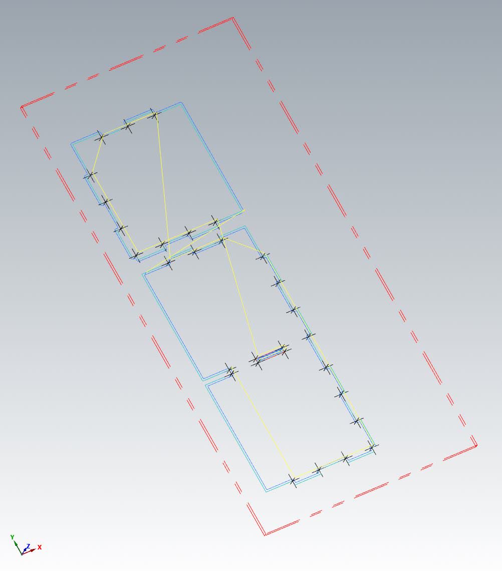
The first thing to do is drill all holes. As you can see below, these points are for all interior slot corners as well as interior corners on the outside of each part. These hole locations are marked with the black crosses while the yellow line shows the tools traversing path
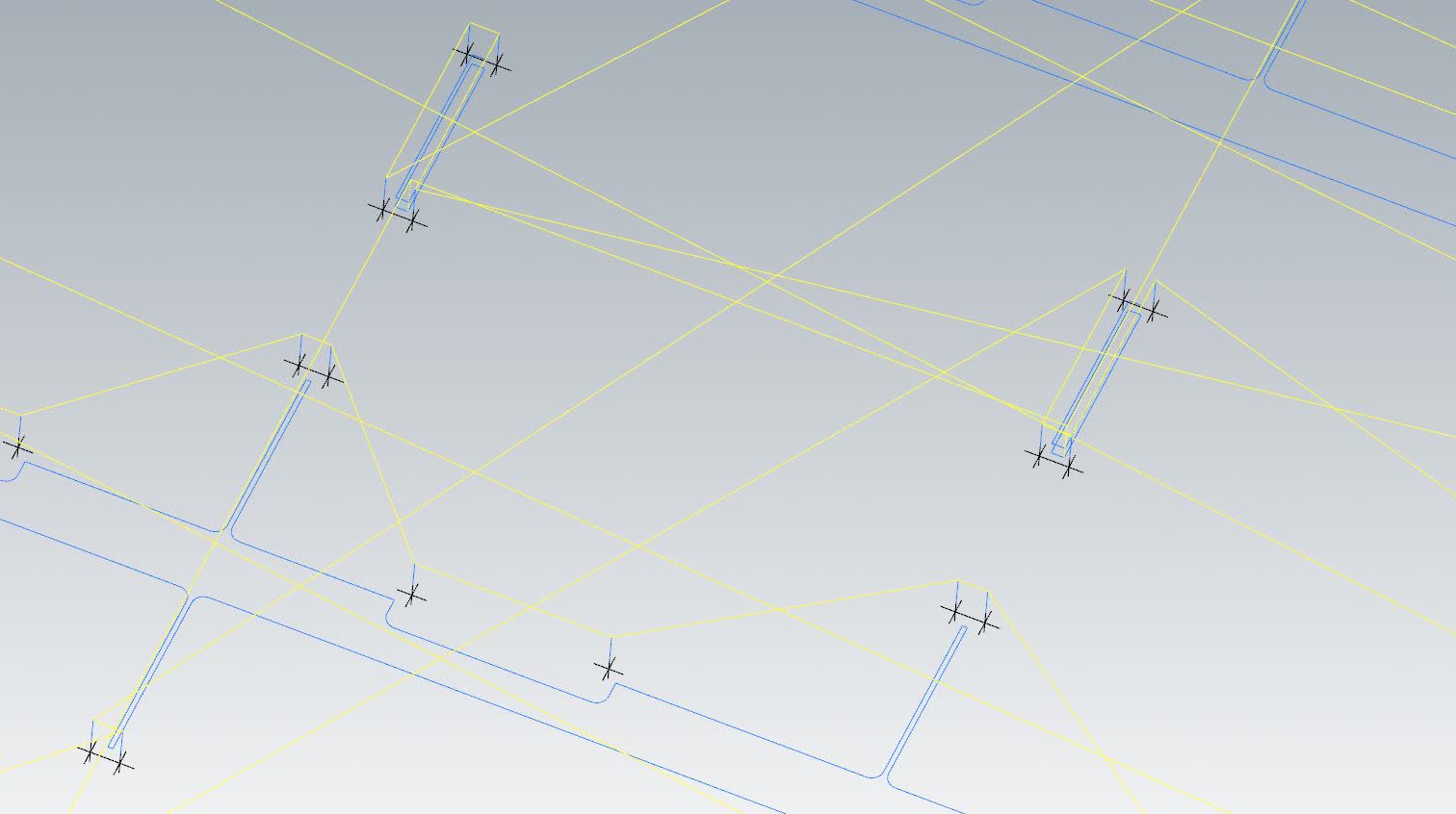
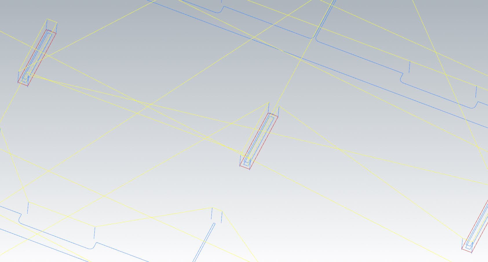
Second, we cutout the interior slots. The tool's path while cutting is the dark blue inside each cutout, the red line shows the exterior dimension after the cut, and the yellow line shows the tool's path while traversing accross the board (ie not cutting). Note that the tool is always on the left of the cut to ensure the desired dimensions are achieved.
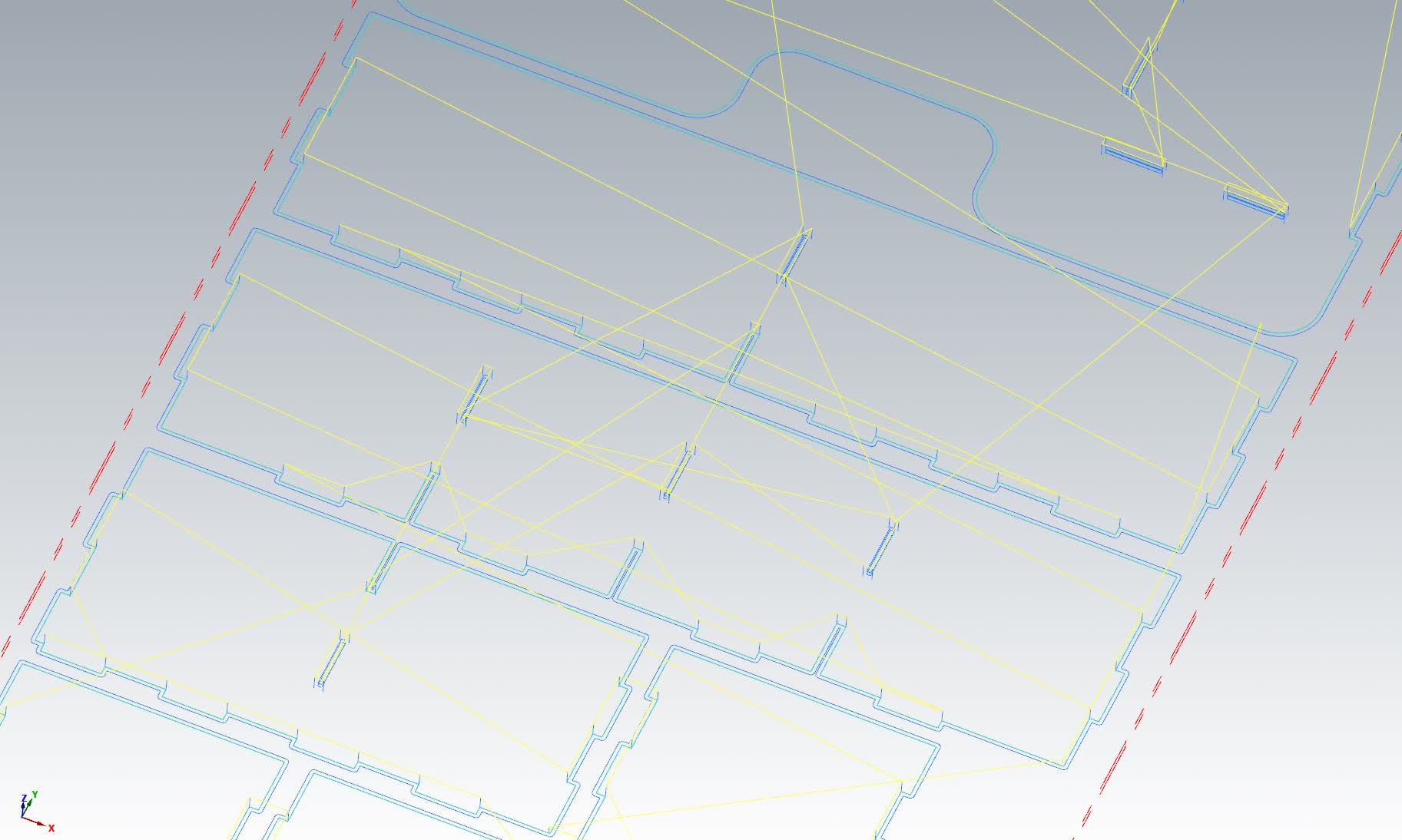
Finally, the the exterior dimensions are cut. The dark blue line shows the tool's cutting path, the cyan line shows the exterior dimensions of the parts after cutting, and the yellow line shows the tool's path while traversing accross the board.
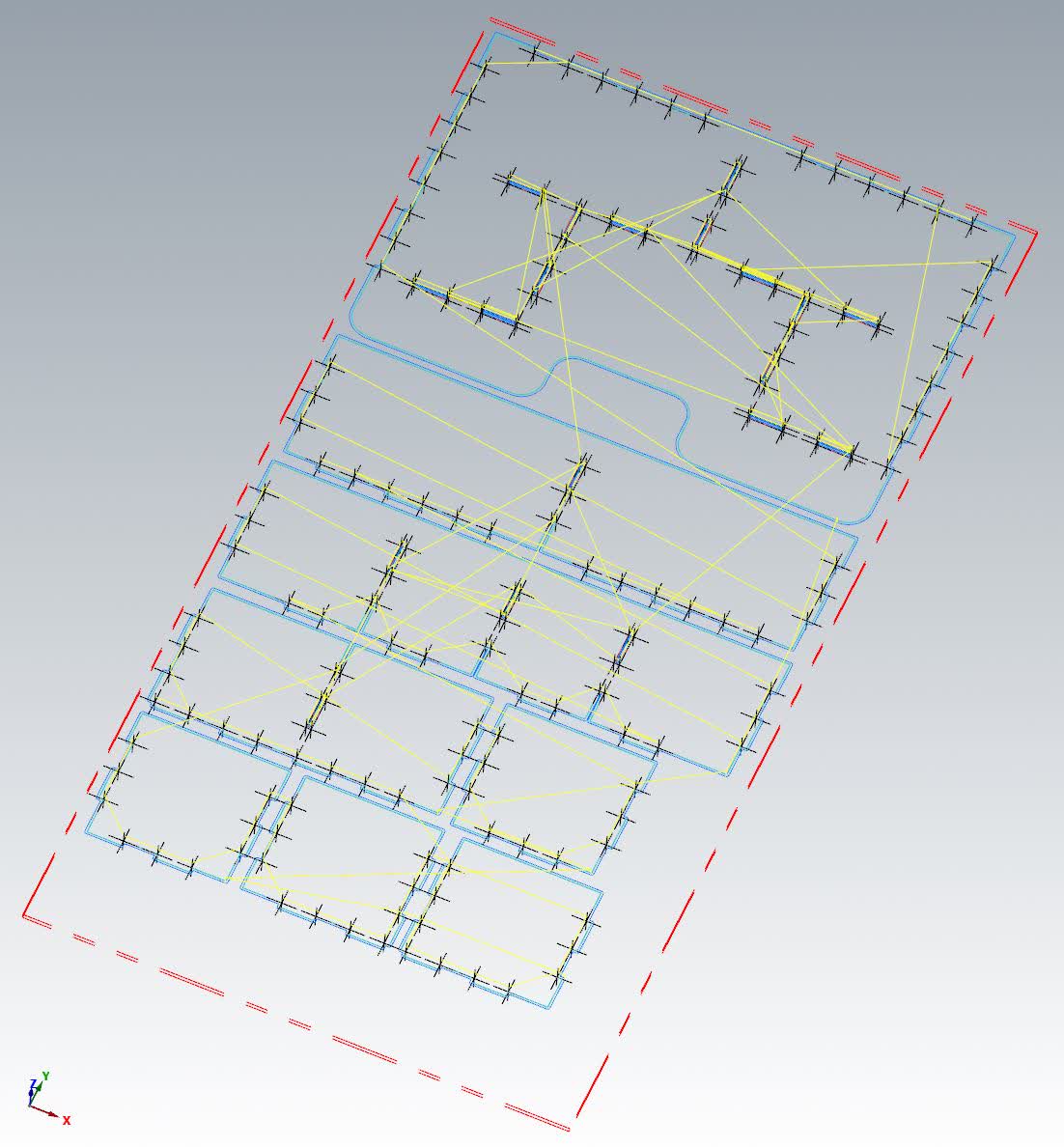
Above I showed close ups to better visualize what's taking place. Below I am showing the busy image of the whole process: Black crosses are holes, then red lines for interior slot cutout, then dark blue lines to cutout the exteriors:
This is for the second smaller board with the same process as described above:
One final note, the depth of the cuts were programmed to go down leaving 0.007" of material (ie not cut all the way through). This leaves behind a paper-thin layer of material called an onion skin. This is done to ensure that the vacuume holds throughout the entire cutting process so that the pieces don't go flying off from the moving tool pushing on it.
With that done, we load the g-code into the machine and we can get started with making this computer model into something physical!
Cutting
I started with the big 8 ft x 4 ft OSB sheet. It was pretty warped. When setting it on the machine's table, it definitely did not lay flat at all. However, After turning on the table's vacuum, it sucked down the whole board and it held it pretty firmly. To be on the safe side, the board was taped along 3 edges to ensure it held in place while cutting, as shown here: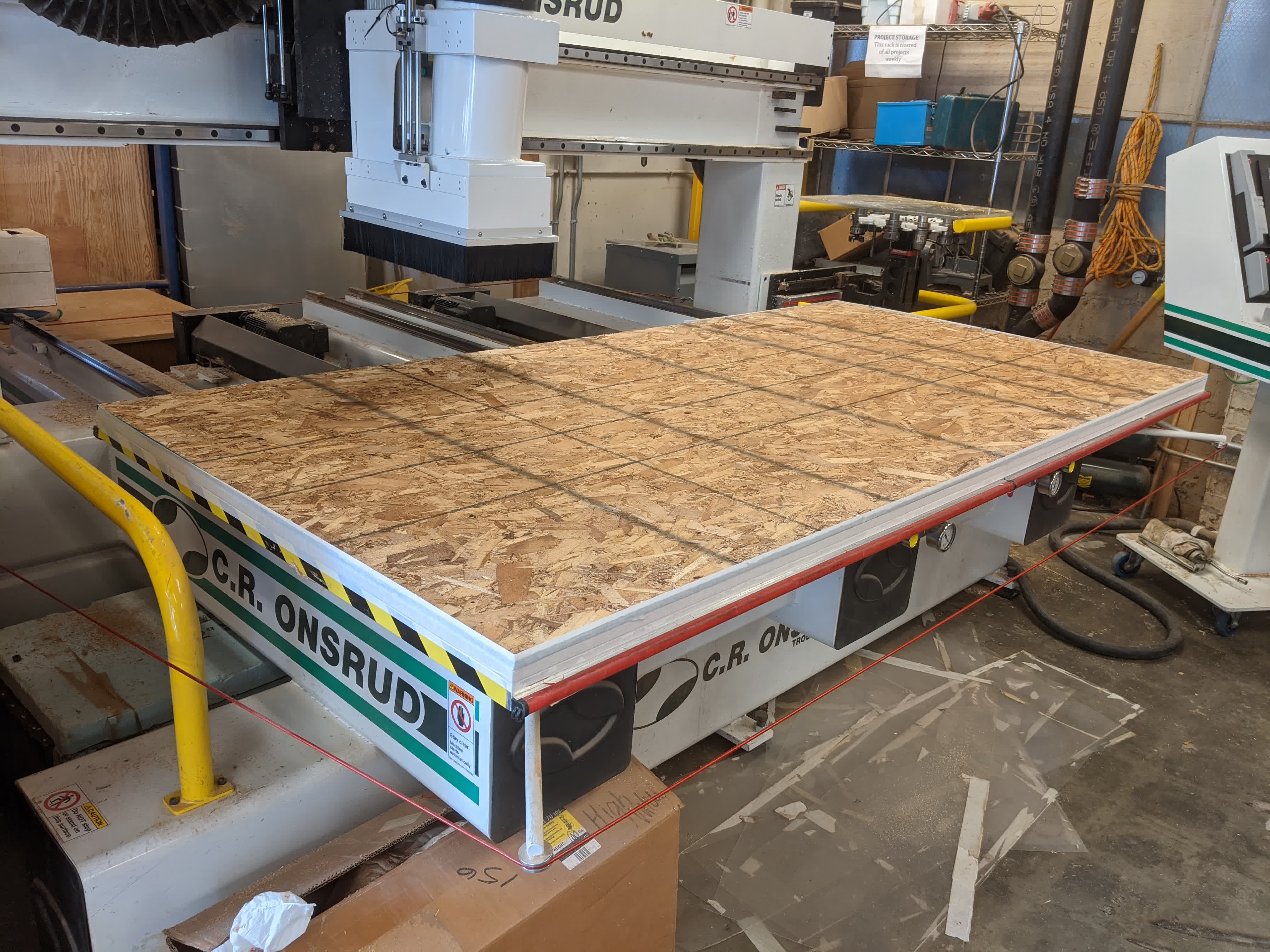
Before running the job, it is always good to do an "air cut". This was done by shifting the z-axis up by 1". The job will run, and the user witnesses the tool path to make sure things run as they were programmed to. Here is an example of this process on the smaller board (forgot to video when I did this for the bigger board):
After making sure things are moving how they are supposed to, the z-axis shift is reversed to zero, and the job is ready to commence. Here is the machine drilling the holes:
Here it is cutting out the interior slots:
and here, it is cutting the exteriors:
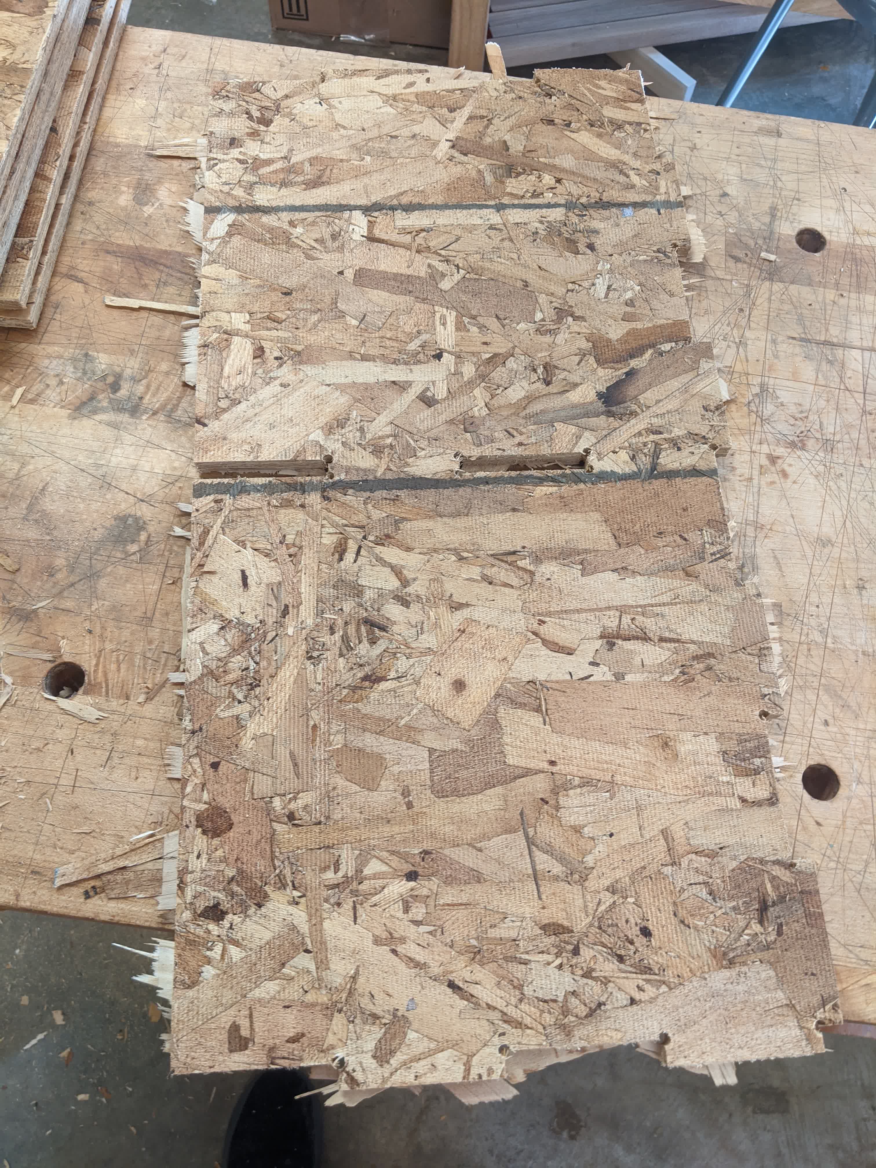
Once that was done, the pieces are removed from the table. As is clearly visible, the pieces of onion skin are still intact at every cut.
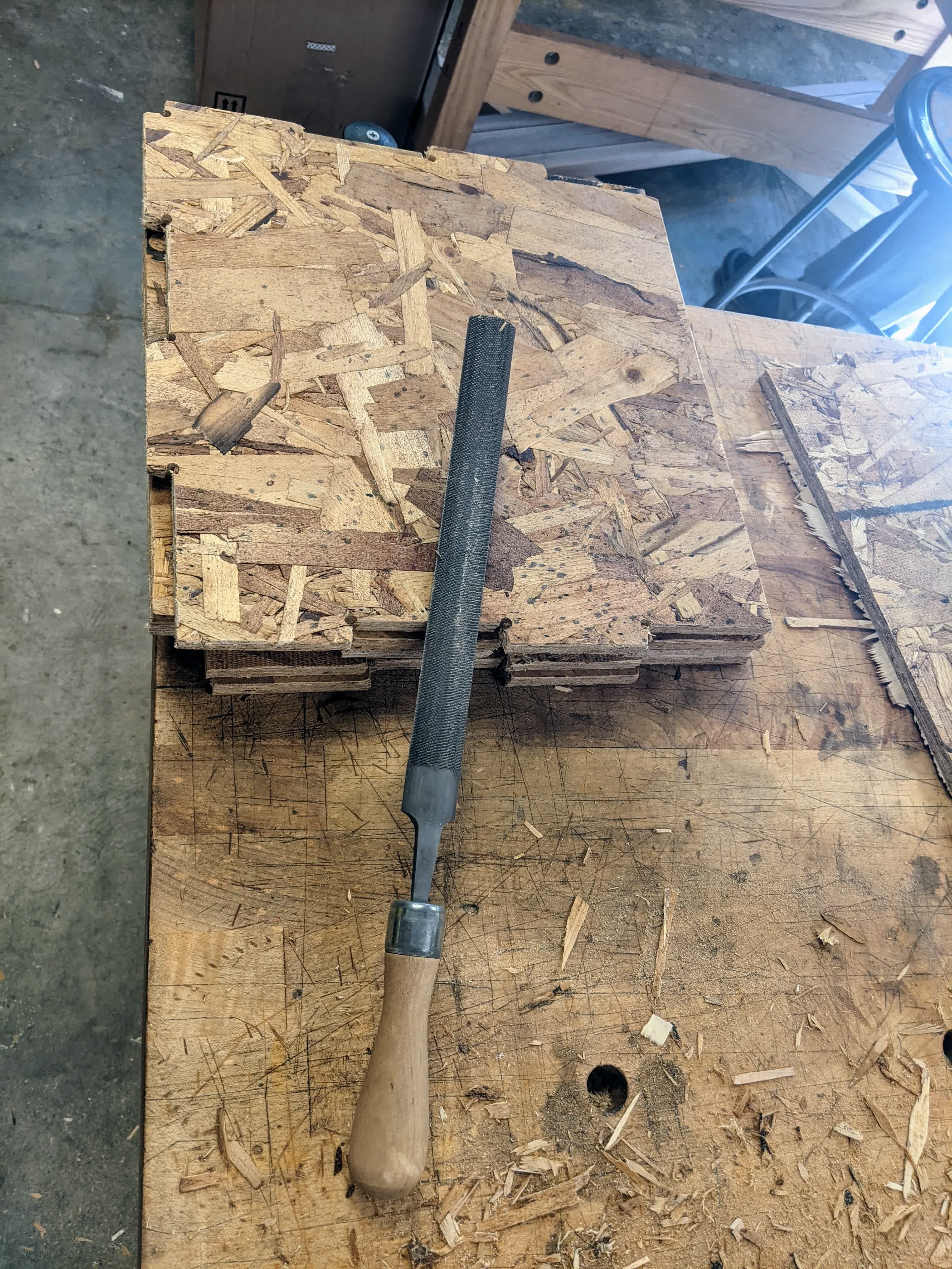
This is easily taken care of with a file. I say easily, but it takes a good amount of time. I spent about 2 hours filing away at every edge. Since this is something I will be using for my daughter, I don't want her getting splinters!
The final step is to take it all home and put it together. This was simple enough as it only had simple press-fit box joints. I did use a hammer in the process, but it wasn't too bad.
Once again, we must see if it passes my daughter's happiness test:
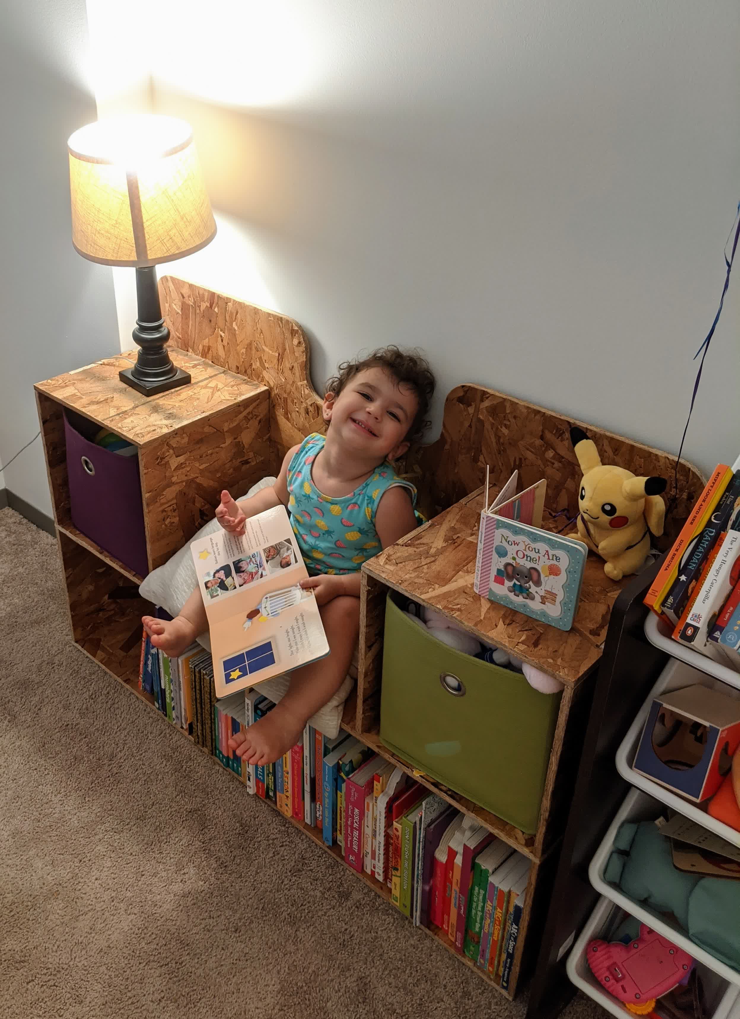
That looks like one happy two year old to me!!
One final thing, can't forget to child-proof this thing! A little foam and double sided tape will do the trick:
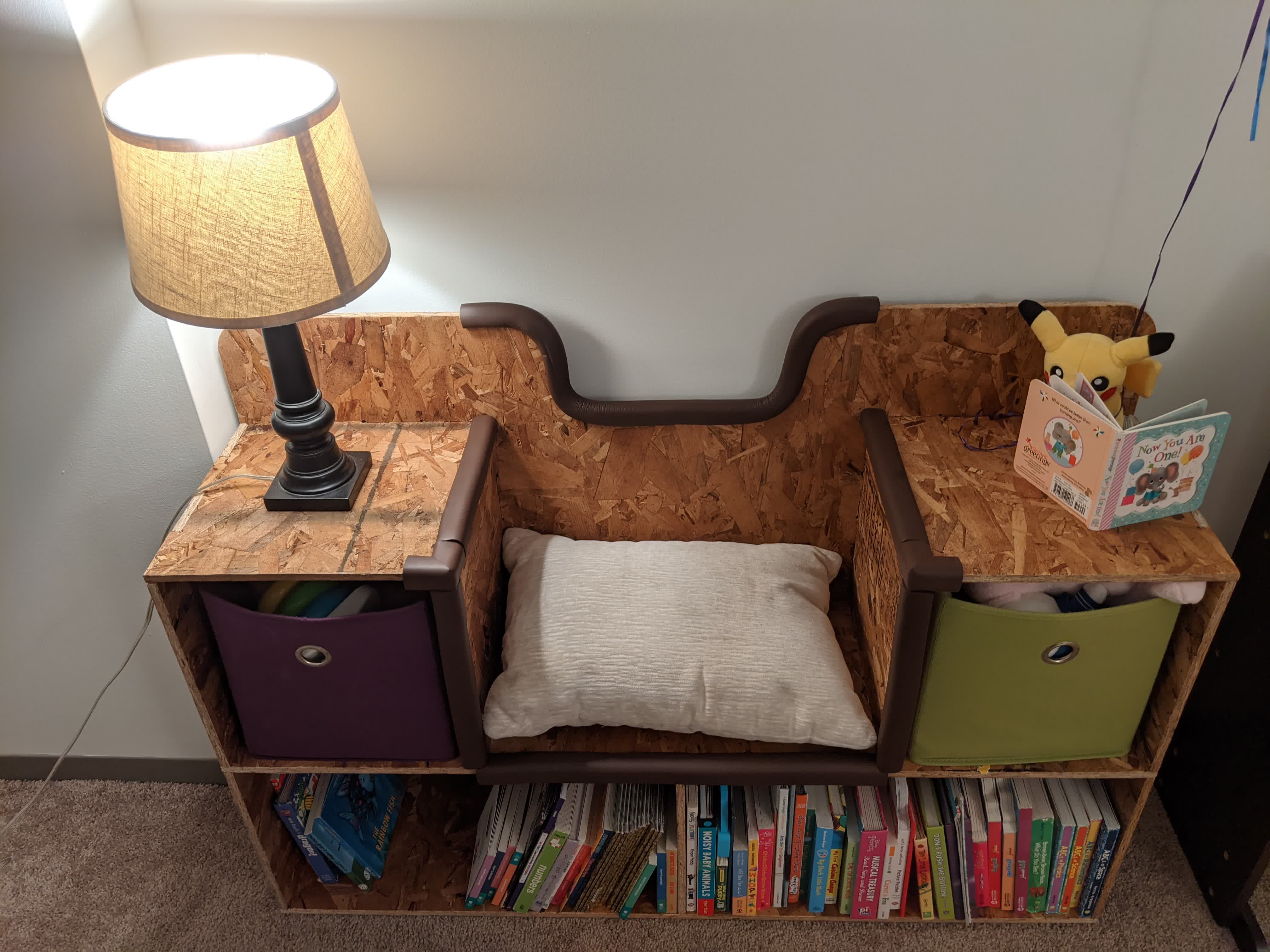
I'm happy we've transformed my daughter's old library on the floor to a new library on the floor with a place to sit :)
Files:
BookCaseBench.dxf
BigBoardToolpath.emcam
SmallBoardToolpath.emcam