Web Design, Version Control, and Final Project Brainstorm
Laser & Vinyl Cutting
3D Scanning and Printing
Make Something Big
Molding and Casting
Electronics Production
Electronics Design
Embedded Programming
Input Devices
Output Devices
Networking & Communications
Interface and Application Programming
Final Project
Group Assignment
We couldn't get to the group assignment this week because many of us were still struggling to get clank up and running. The group assignment was to use the test equipment in the lab to observe the operation of a micro controller circuit board.Electronics Design
Assignment: redraw an echo hello-world board, add at least a button and LED (with current-limiting resistor), check the design rules, make it, and test it.
I decided to go with the ATtiny1614 microprocessor board which was shown in the tutorial due to lack of time because of how long it took me to get clank up and running. First, I reviewed the datasheet for the microprocessor.
I needed to figure what this thing was, what it does, what all the pins do, etc.
Design
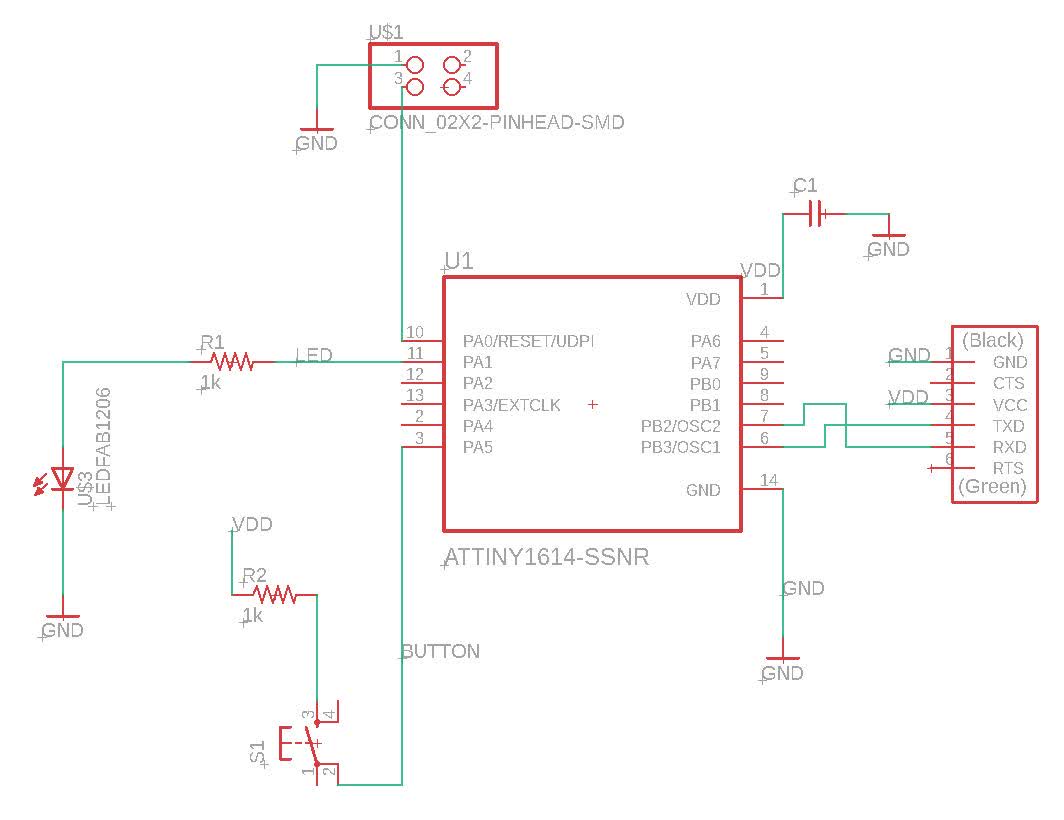
I chose to use Eagle for its integration with Fusion 360. I'd like to use it for my final project. I pretty much followed the tutorial made by Anthony. We started by drawing a schematic where we throw down all the components. The components I have are the following:-ATtiny1614 microprocessor
-2x 1k Ohm resistors
-a 1uF capacitor
-a 2x2 pinhead connectors
-a 6 pin FTDI header
-an LED (I chose red for no reason)
-a tactile button
I then connected all the parts. Things to note are a resistor on the positive leg of the LED to limit the current going to it, and the transmitter pin on the FTDI header going to the receiver on the microprocessor and the receiver on the FTDI header going to the transmitter pin on the microprocessor (I initially had them flipped), and the capacitor serving as a bypass filter. Here is the schematic of the circuit with all its components and connections:
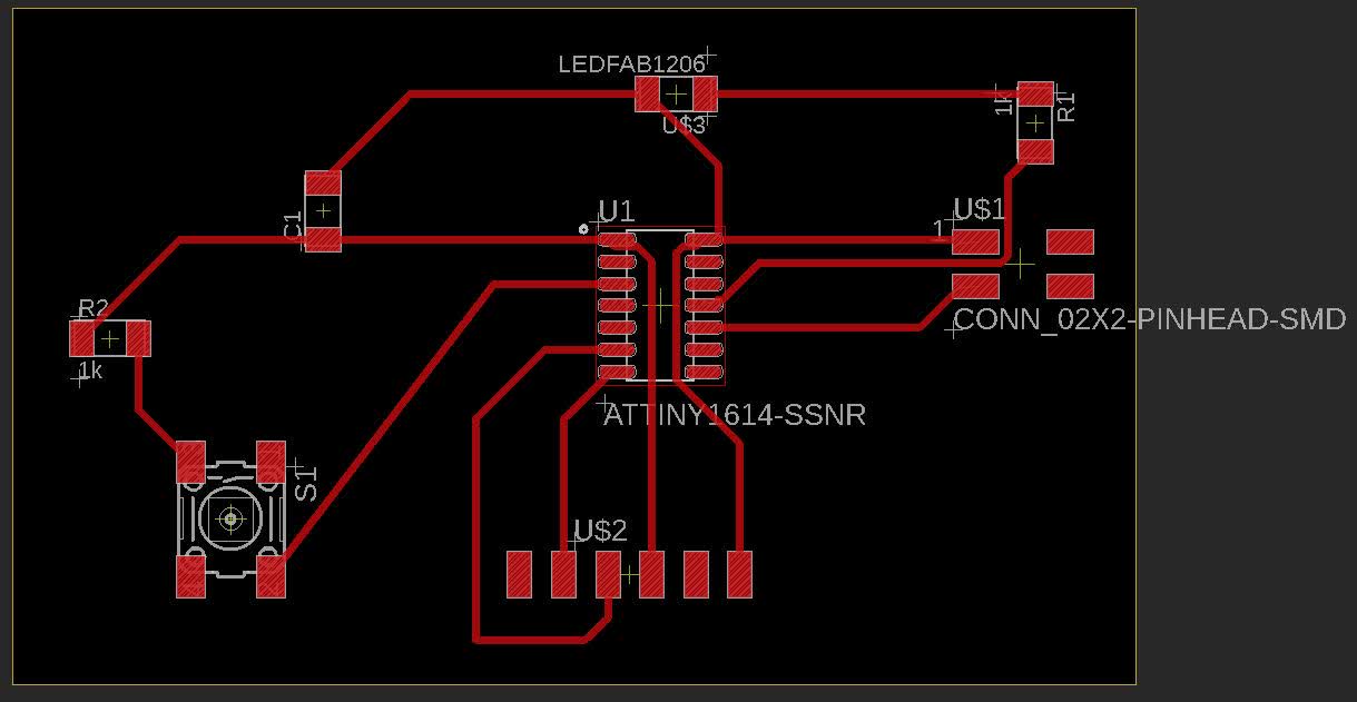
Then I moved on to generate the physical footprint and routing traces which was a bit tricky.
Cutting
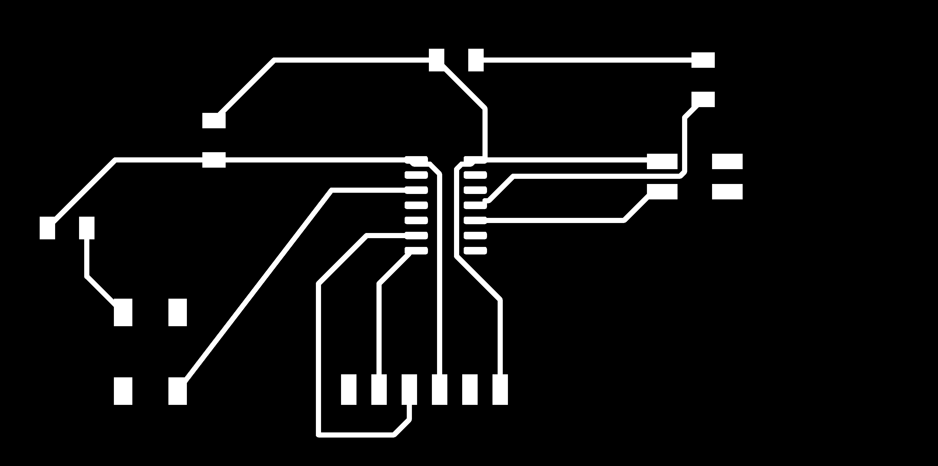
I exported a png of this and imported into inkscape to generate the gcode in mods. It took me a while to figure out Inkscape. The key takeaways are to import the image and maintain the dpi from file, and export the png by manually setting the dpi to what I originally set. Inkscape wanted to change the dpi which would change the dimensions.Here is the png of the trace:
and here is the cutout:

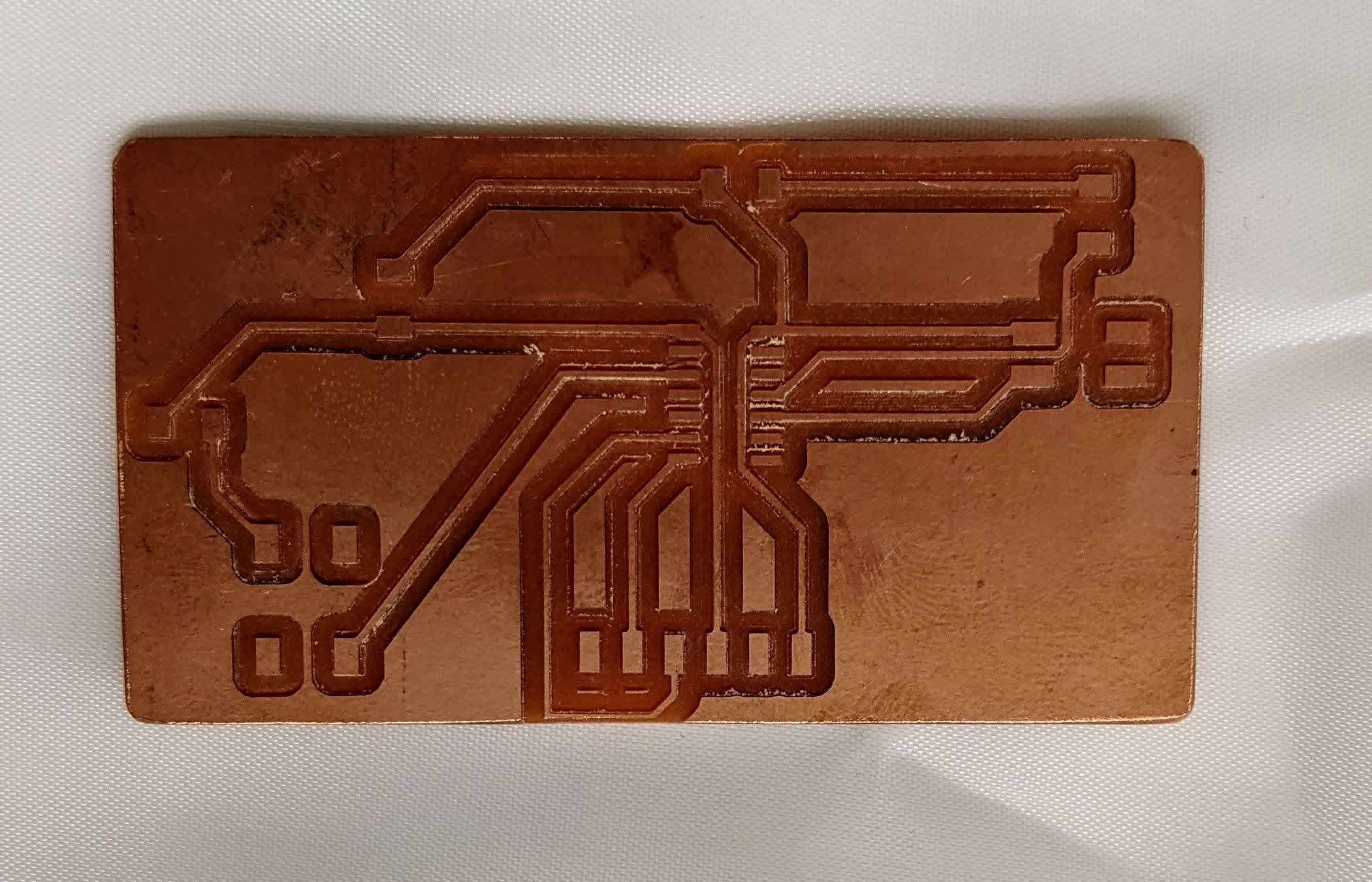
I generated the gcode in mods with the following settings settings for the traces: V engraving bit, cut depth of 0.002", max depth of 0.008", 6 offsets, and cutting speed of 1.5mm/s. It took about an hour and a half, but the wait was well worth it. For the cutout, I generated the gcode using the following: 1/32" flat endmill, cut depth of 0.01, max depth of 0.07, 1 offset, and cutting speed of 1.5mm/s. Here is the result:
Obviously this did not go according to plan. It cut what I didn't want to cut. This is a reminder to always check the toolpath before you cut, and invert the image if its oposite of what you want. Here is a video of cutting out the traces:
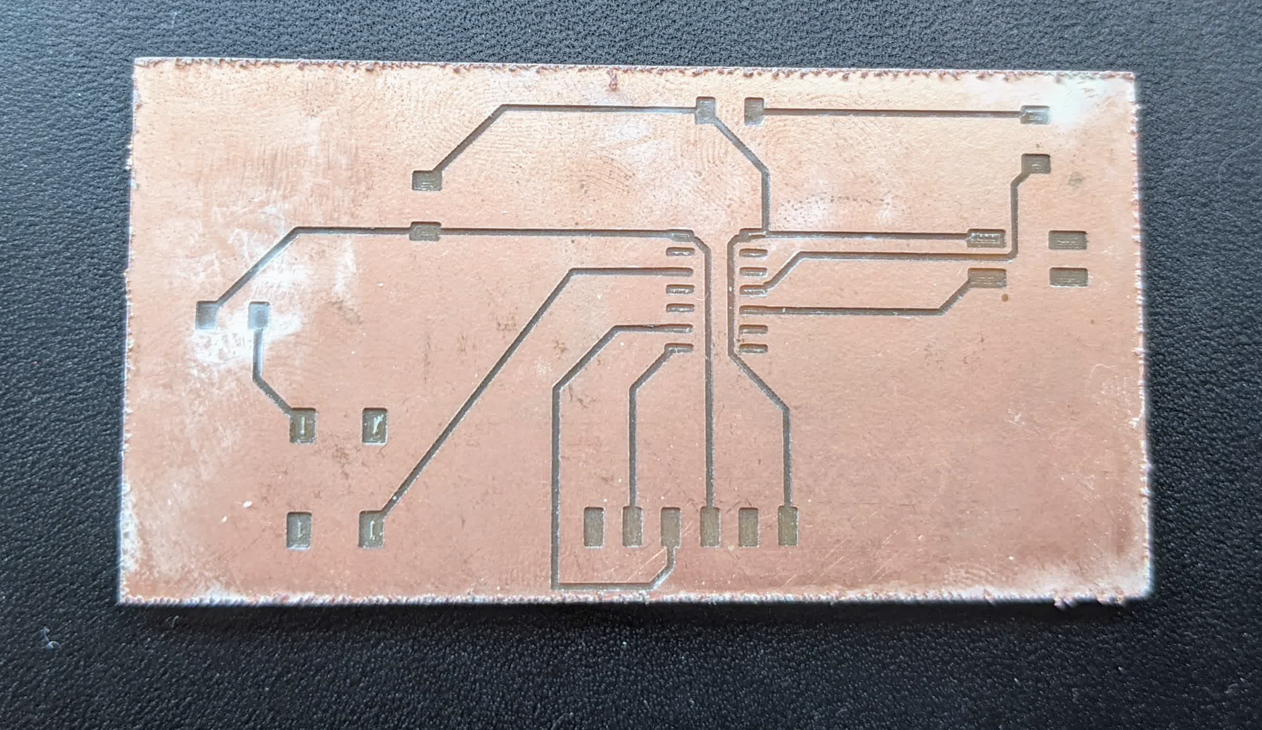
Here is the real final result:
Stuffing the board
Like last week, I laid out all the components listed above. Here is an image showing that: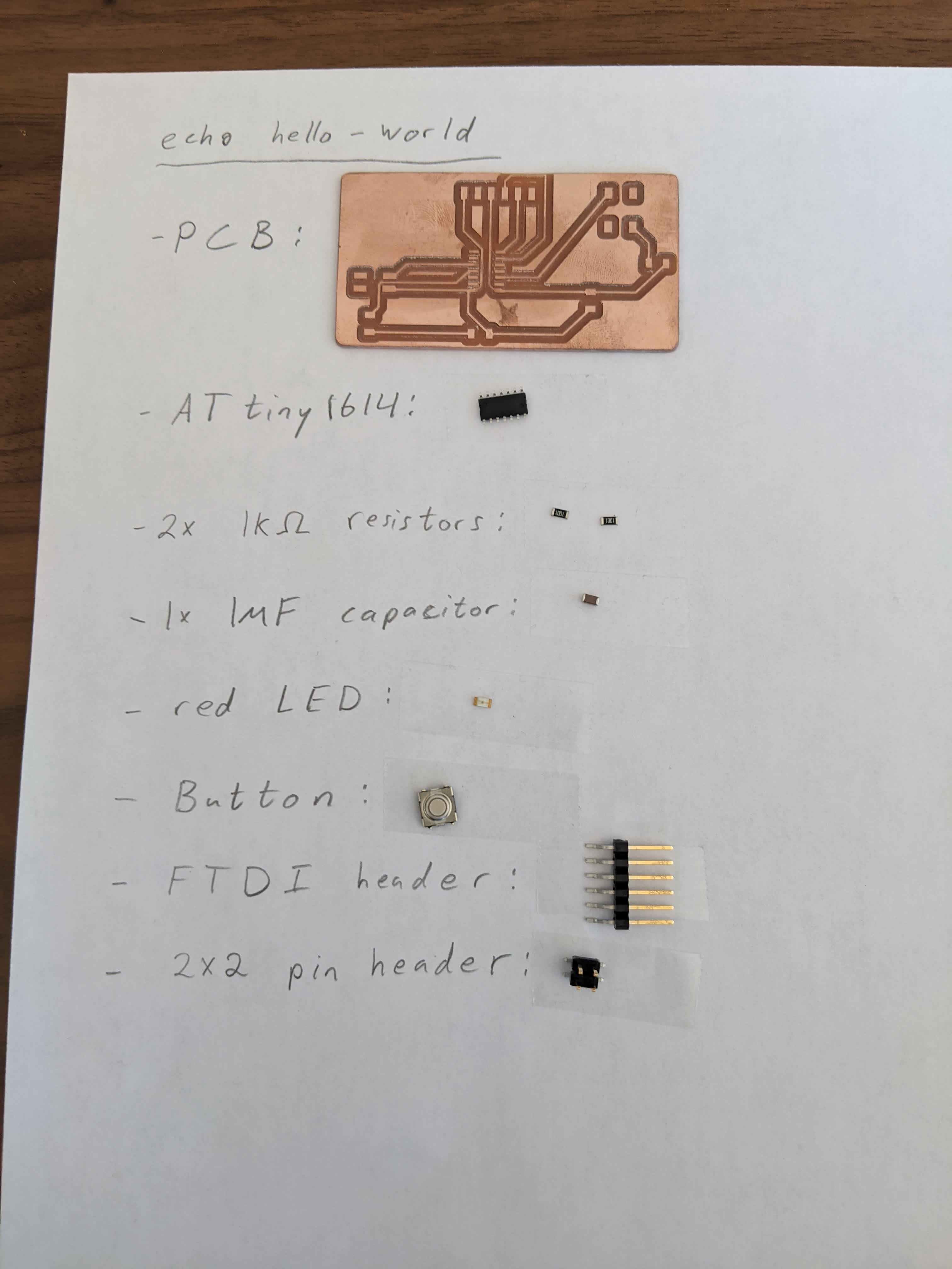
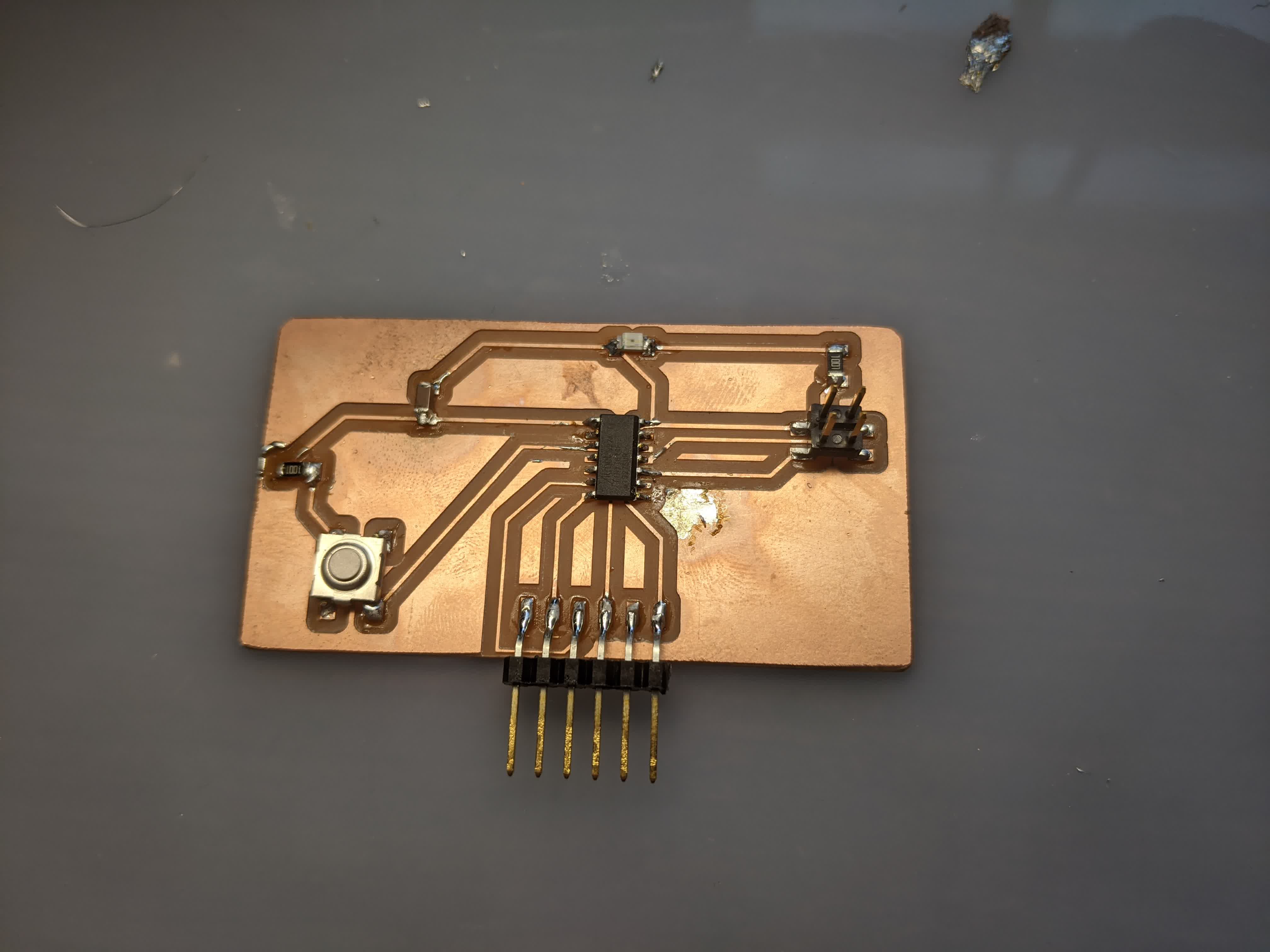
Here is the stuffed board:
Programming and testing
So I didn't have time to do this this week, and then I found out that this was basically the assignment for next week.Proceed here to see how this went.