Final project idea
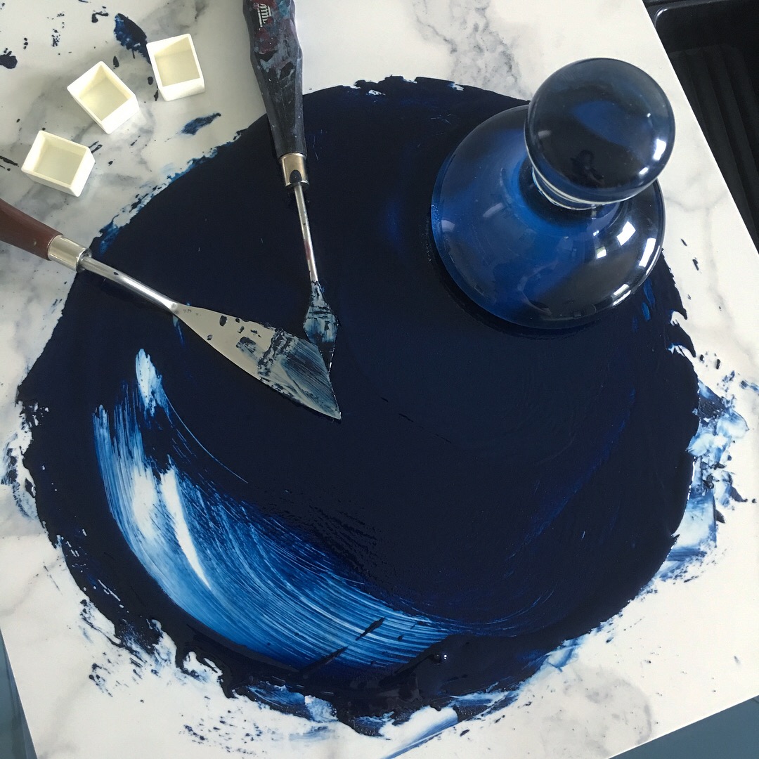
One of my hobbies is manufacturing watercolor paint by hand! Here's a progress shot of making milori blue paint. I use the pestle-shaped tool (muller) to incorporate the pigment into the binder by sweeping the paint around in circles.
3 roll mill
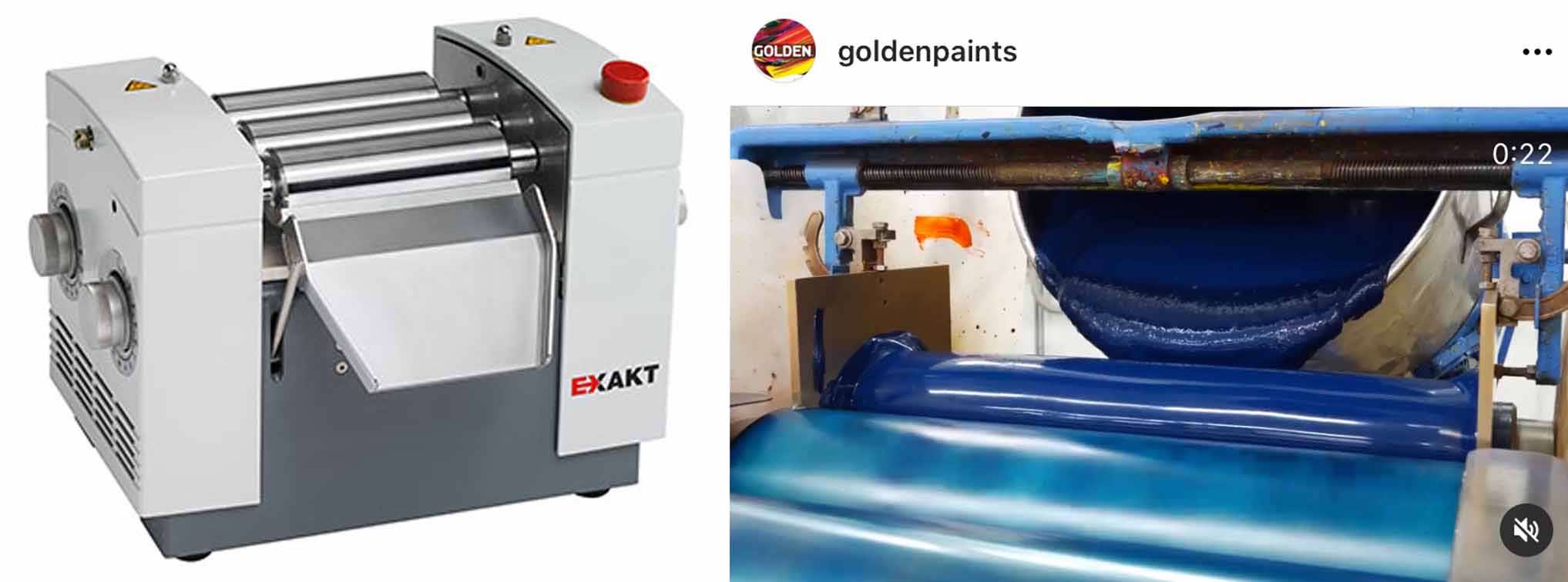
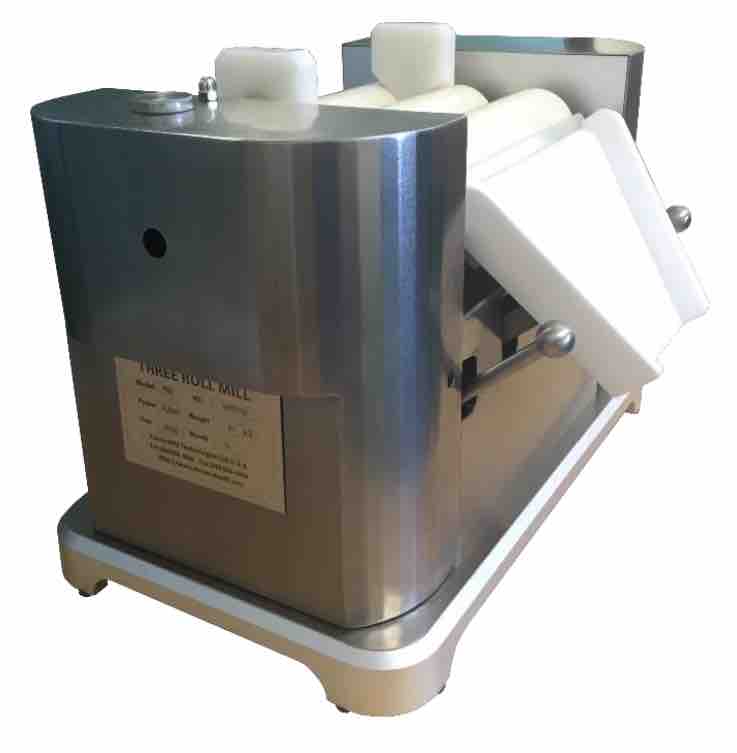
This process looks different for professional paint manufacturers; since they need to make paint in bulk, they use a 3 roll mill to mix everything together. 3 roll mills ensure that the pigment particles are a homogenous size and are fully incorporated into the paint binder. I'd love to make a 3 roll mill to make my paintmaking process more efficient, as I would be able to make paint much faster and at a greater volume.
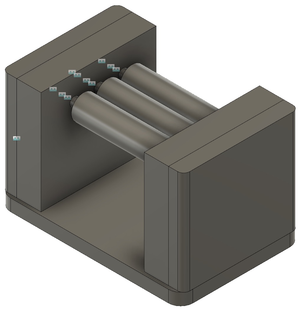
Preliminary CAD
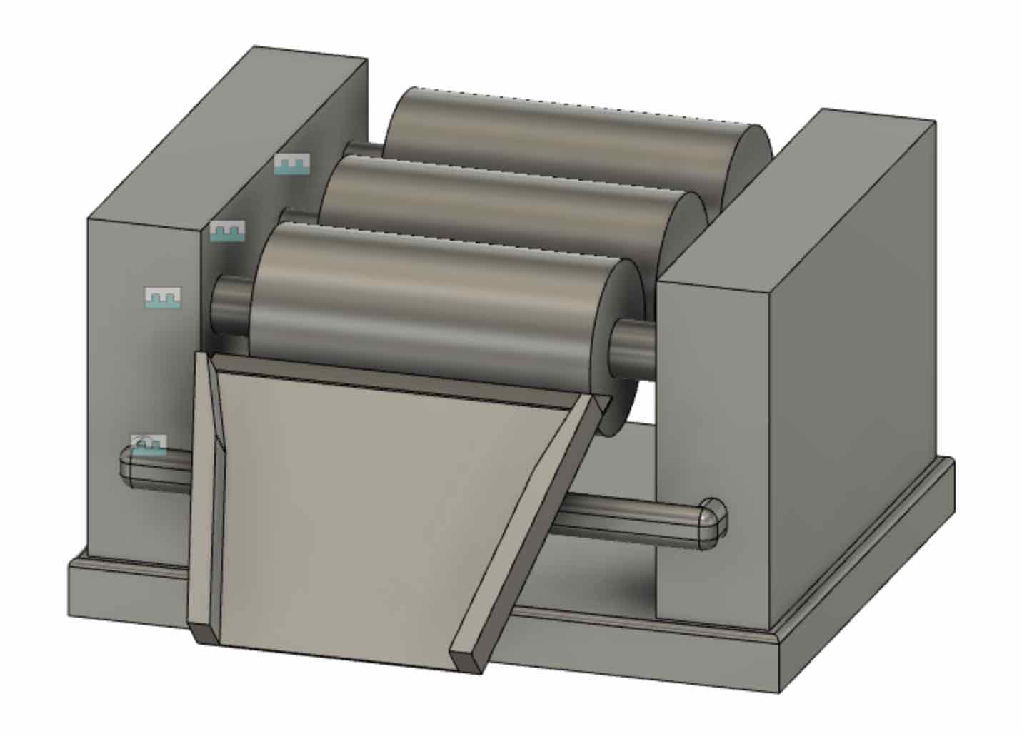
Here's the first CAD design I made for the device. The dimensions of the mill without the apron/trough are 12.5" x 9.5" x 7"
Research Pt. 1
I talked with Dan from the LMP about how to actually make this device, and he said it wouldn't be
a big deal to machine. We weren't sure whether mill rollers are adjustable or not, an element that would highly impact
our design and the performance of the machine; my next step was to do some research. I reached out to a prominent paintmaker I
follow on social media to ask about her mill, and she confirmed the rollers are adjustable and that she moves them closer for
each pass of paint. I just followed up with her again, since she said she'd send me the owner's manual for her machine.
Once I take a look at the manual, I'll have a better idea of how the adjusting system works and can move on to a more concrete design!
Research Pt. 2
The paintmaker couldn't find her manual, so I reached out to Torrey Mills, the company that she bought her mill from. I didn't get an email or call back after a request to talk
about their mill design, which is understandable since they probably don't want to share their methods with someone who could potentially establish a rival mill company (saying you're studying
mechanical engineering at MIT helps with credibility, but could also sound threatening).
Then I just searched for manuals on their web page and found one for the tabletop 3 roll mill, which was a lot more efficient. And their manual is fantastically
detailed, explaining all the dimensions of the machine components, showing images of the gear train, and listing materials. The only element excluded is the mechanism
for adjusting the rollers; there isn't a picture, though the manual does say the system consists of turning knobs attached to screws connected to tensioning springs. Hmmm...
Brainstorming - 10/31
I met with Dan again to share the results of my research, and we wound up having a brainstorming session on how we'd build the machine. We specifically
thought about the adjusting mechanism, working off of the clues from the manual. We figured out that when you turn the knobs on the sides of the machine,
the screws push the roller bearings closer or farther apart, with the tensioning springs in between each square bearing. But how would tensioning springs
work with a gear train? Wouldn't moving gears closer or farther apart ruin the gear train? After some more research, it turns out 3 roll mill rollers move
on a micrometer scale, so moving them wouldn't really impact the gear train, especially if the gears have long teeth. We also counted the gears' teeth from the
manual's diagram and started researching gears on McMaster.
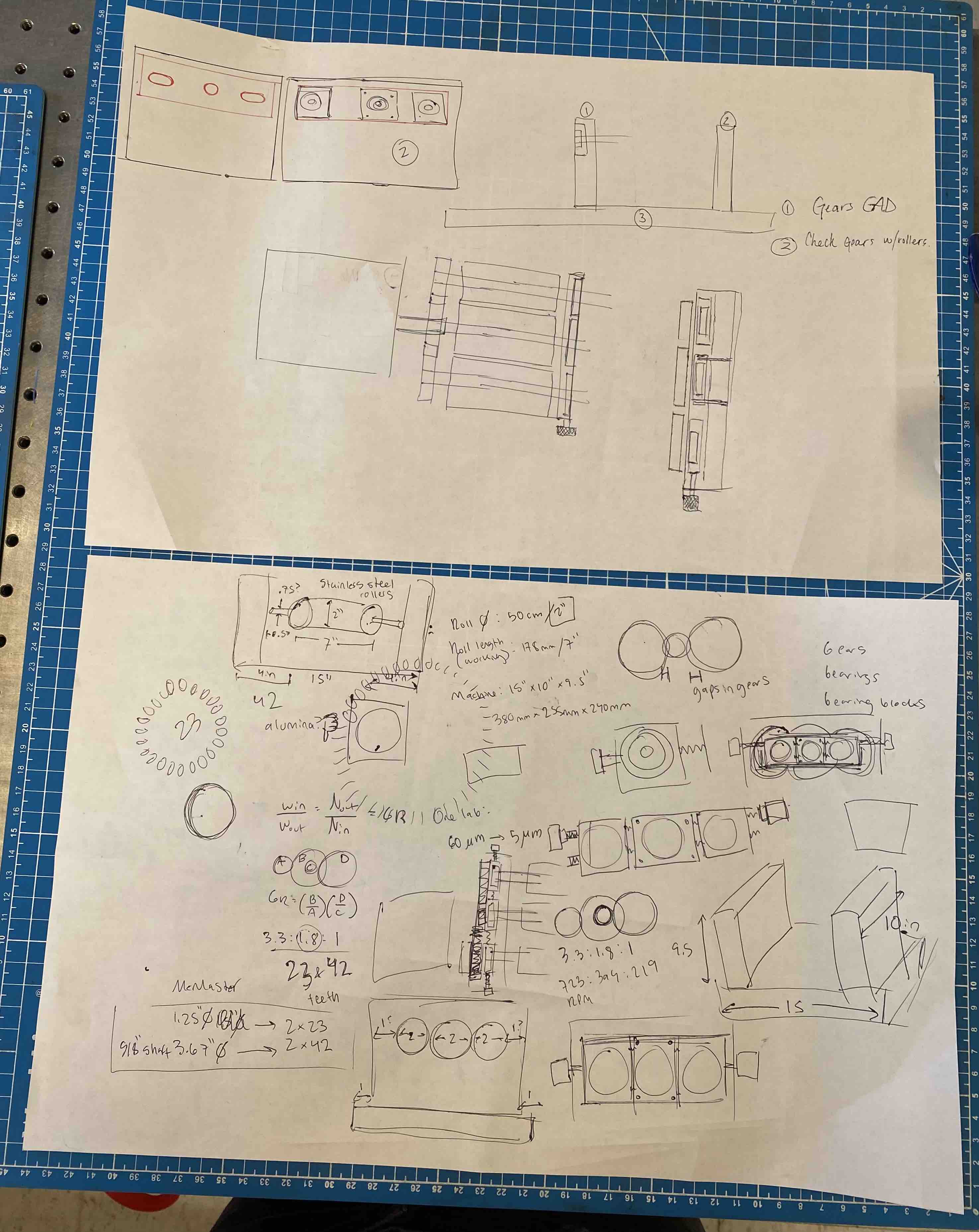
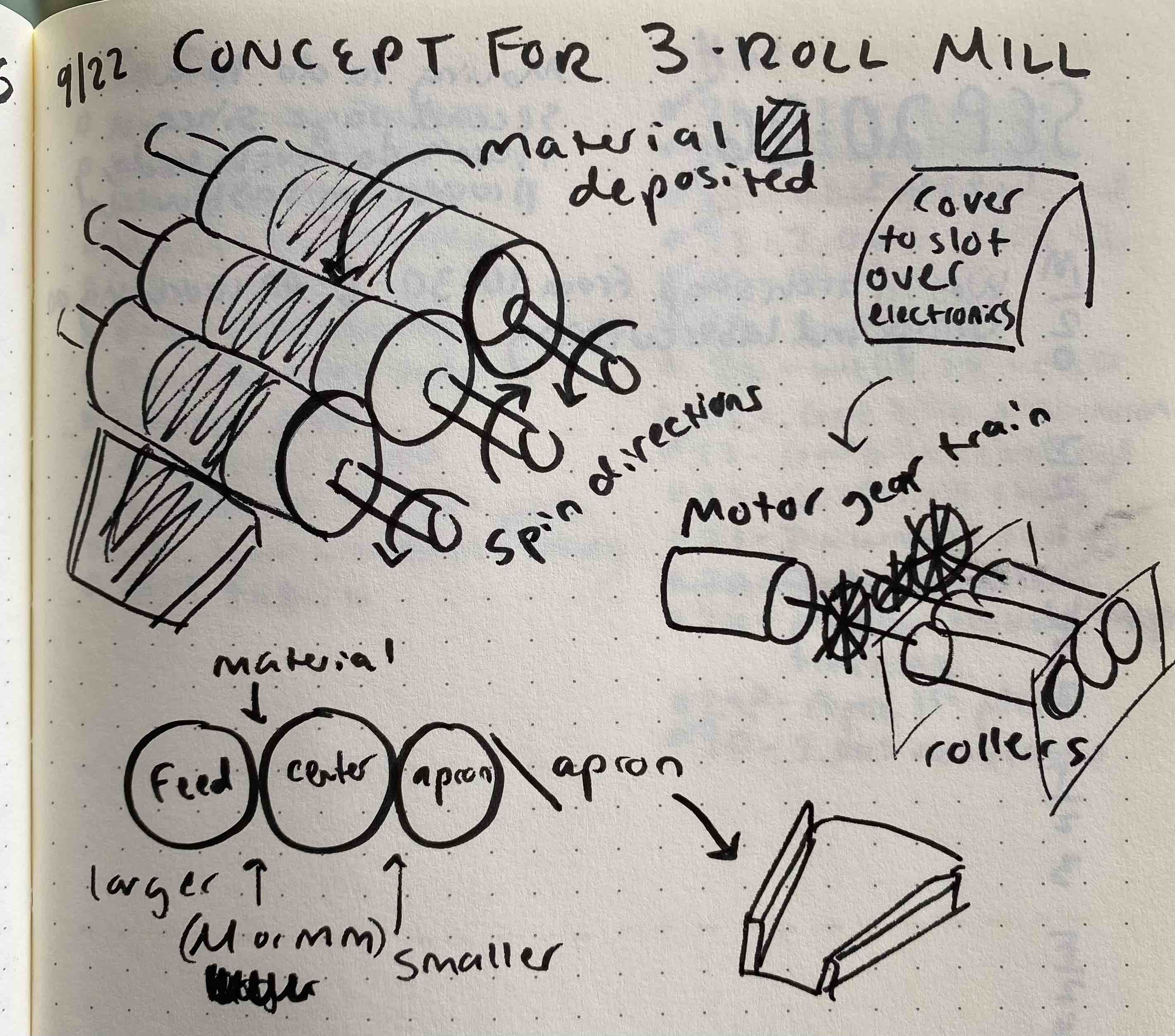
Here are our brainstorming sketches and notes. Dan's are pretty neat, while mine are chaotic. The next step for me is to CAD each component, then make drawings, before we can start machining. To do this, I'll download the CAD files of the gears we found on McMaster to use as reference for the dimensions of the roller bearings.
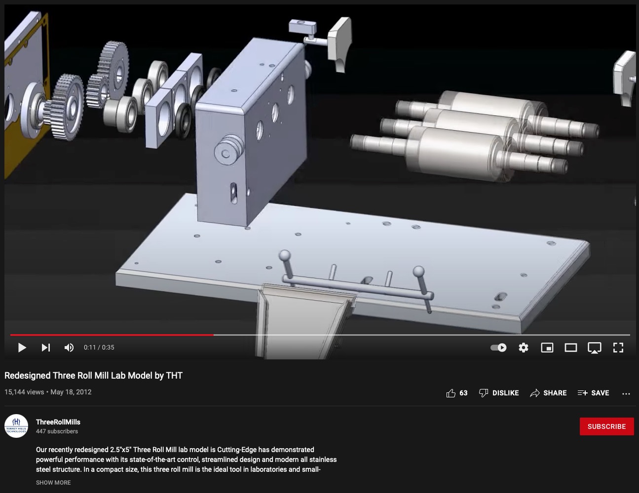
I've been using this video from Torrey Mills as reference for my design. Strangely, there's not much info on 3 roll mills online, so I was super lucky to find this video detailing the CAD. Seeing all the individual parts has been so helpful for determining what I need for my design.
Final project review with Calvin - 11/7
I met with Calvin in N51 to discuss my final project. I updated him on my progress so far, and he recommended using the upcoming weeks to work on learning what's required for my mill's electronics.
Fabrication plan as of 11/7
Here are the required elements of our final project and how I'll satisfy them:
Additive and Subtractive Processes: I'll turn the rollers on a lathe and use 3D printing to make the buttons for stop/start/etc.
Electronics Design and Programming: I'll make a PCB to control the motor that turns the rollers and wire it to the machine buttons.
Input week: learn to make a PCB with a potentiometer
Output week: learn to control a motor with a potentiometer
System Integration and Packaging: I'll assemble all components (rollers, gear train, electronics) in a frame with a metal structure and
thermoformed covers (to make it look professional).
Designing - 11/12
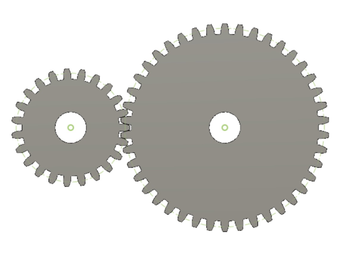
Although Dan and I had picked out some gears on McMaster, upon downloading the CAD files for them, I discovered they didn't mesh. I perused the options on McMaster, this time paying attention to pressure angle and diametric pitch to make sure the gears would fit -- I realized I
should be flexible about the gear ratio, as 23 and 42 tooth gears were rare, but then realized that it didn't matter; the options on McMaster were super expensive. Upon chatting with Dan, we decided it would be more cost-effective and efficient for us to machine our own gears. CADing the gears turned out to be super easy, since Fusion has a gear plug-in where you input the gear dimensions and it automatically generates one.
I also made some general components of the device, using parameters for key dimensions since I hadn't yet determined the exact dimensions yet. I had thought that I would use the McMaster gear sizes to size the bearing blocks, which would size everything else; now designing the gears, I had so much flexibility with the dimensions that I wasn't sure if I should just pick a number and go with it.
Meeting with Dan and Dominic - 11/15
A few days after CADing, I visited the LMP to discuss the project with Dan, as we've decided to that meet regularly. We picked out skateboard bearings on Amazon (cheaper and would arrive faster than McMaster), which informed the bearing block dimensions. We decided that I should CAD all parts of the mill despite being uncertain about dimensions (huzzah for parameters) so that we'd have more to work with.
I wound up chatting with Dominic, a MechE senior with a lot of technical experience, all about motors (it was output devices week). I didn't know where to begin with researching motors for the mill, so he was a huge help! We started by using the viscosity of paint, speed of the rollers, and gaps between rollers to determine the torque required to run the mill, then used that to figure out watts and voltage. In the end, we determined that the motor stats in the Torrey Hills manual were, indeed, correct for milling paint:
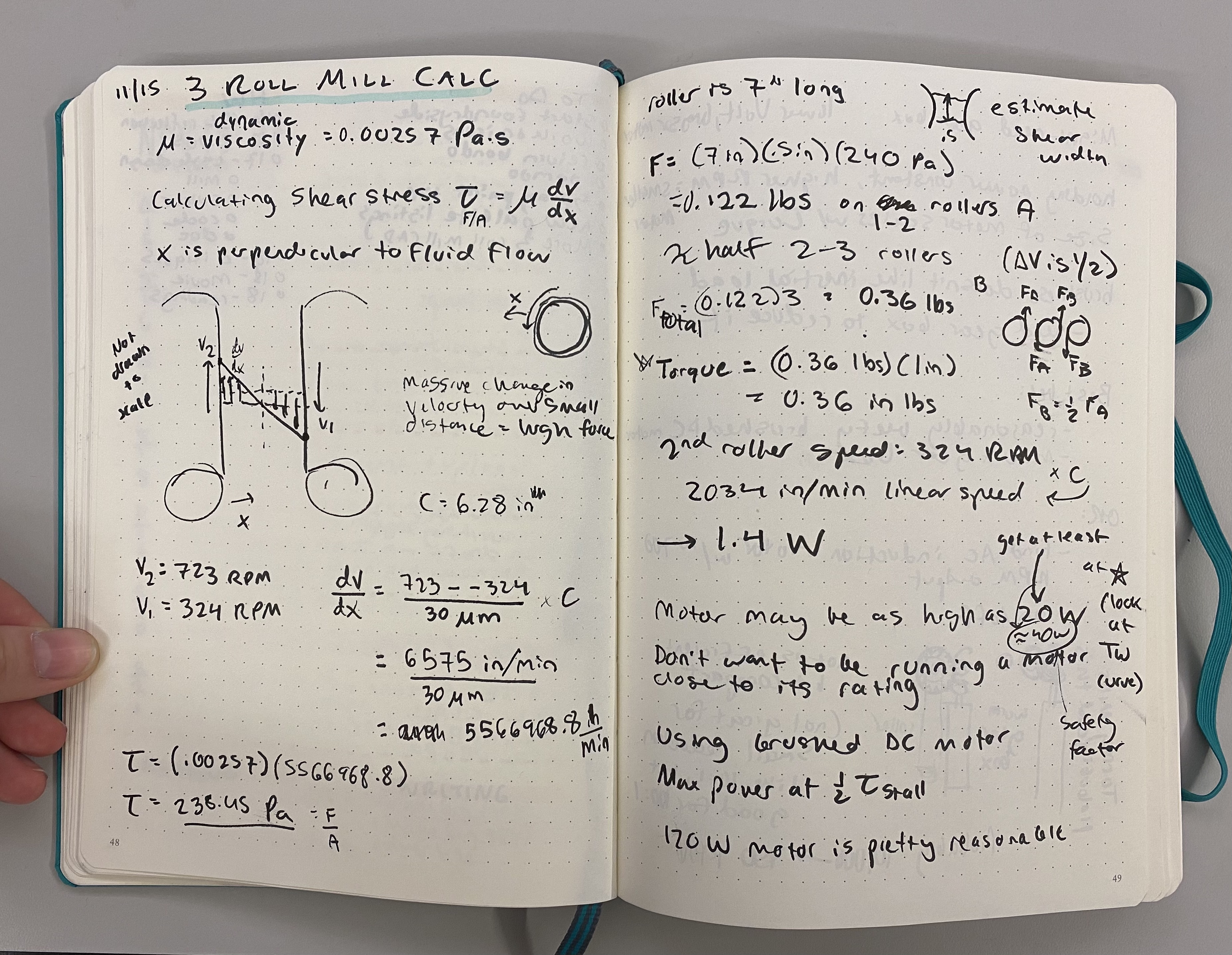
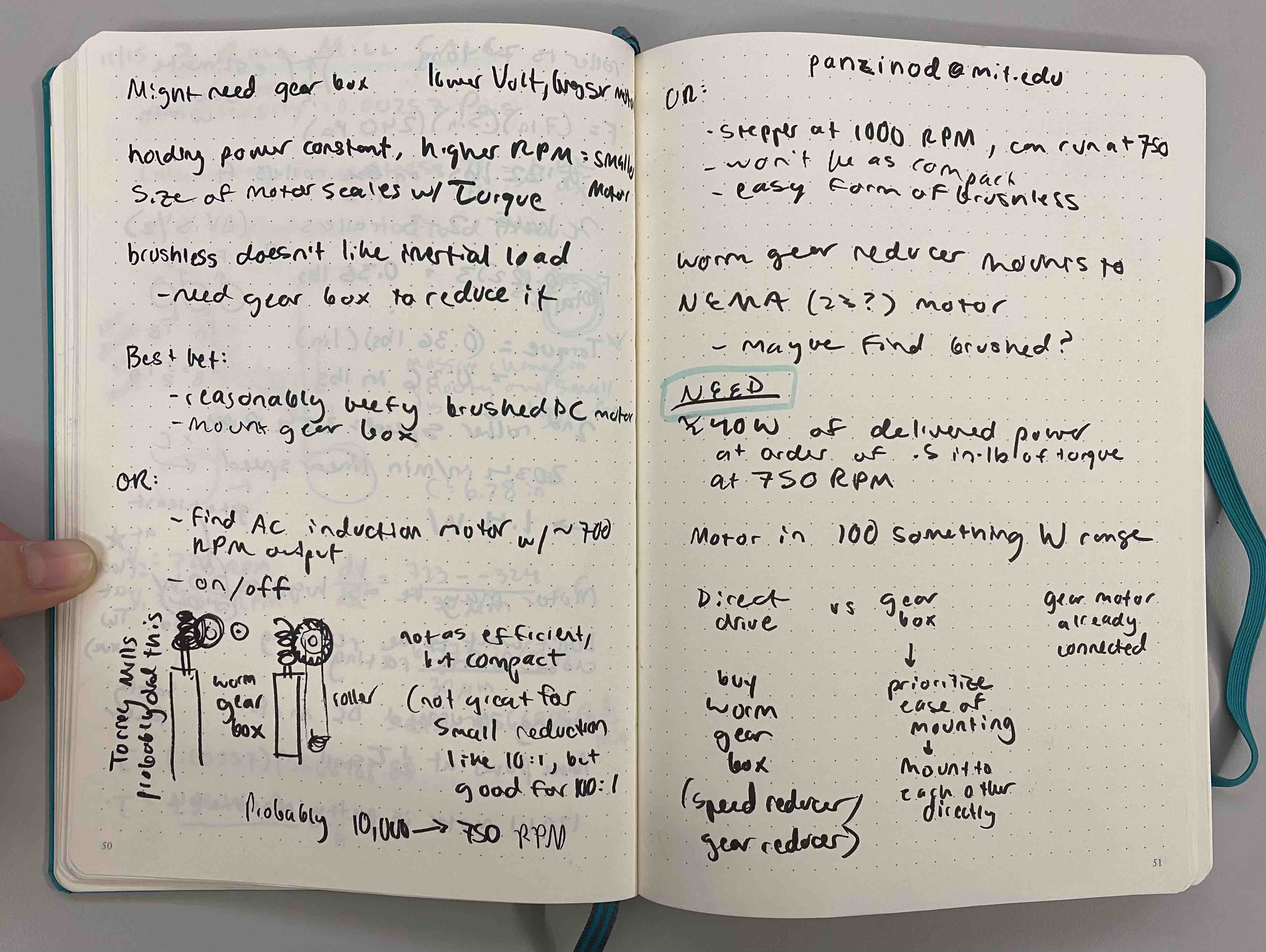
Dominic walked me through the differences between brushed and brushless motors and DC and AC motors; we ran through several options for what I should look for in a motor. Bigger motors will have a lower output speed, while smaller motors will have a high output speed and may require a gearbox to reduce the RPM. I don't want a huge motor, so I'll try to go with the latter option, but then I need to consider how to mount a gearbox. And I still have to find a motor with the correct specs, which may be tricky. It's a lot to think about, so I'll have to come back to the motor later and return to CADing/designing in the meantime.
Designing and Planning - 11/21
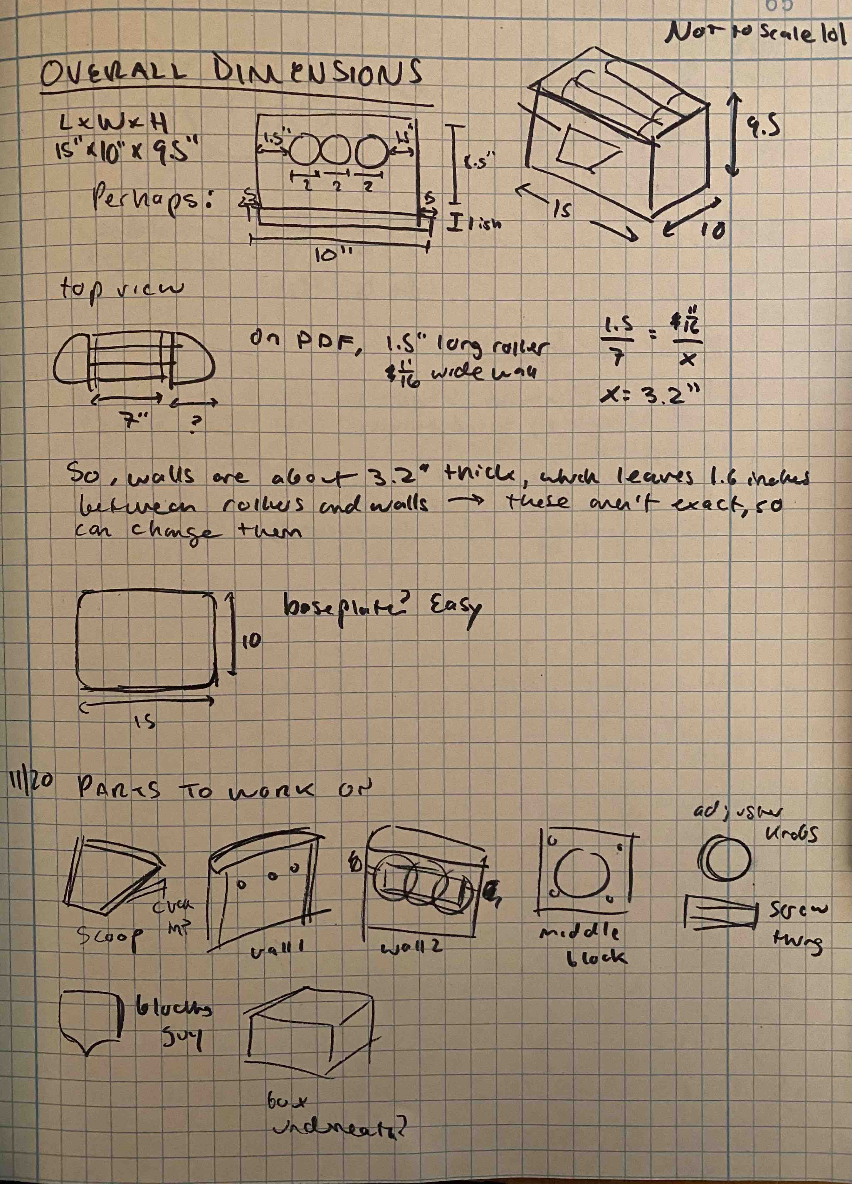
At this point, in order to progress, I had to refine my design. In my engineering notebook, I figured out general dimensions for the size of the mill by using my manual and the CAD video as reference. I also listed all the individual parts to CAD to help me visualize my next steps.
My process has been this: CAD using many, many estimated parameters so that I actually have a model, then refine those parameters once I talk to Dan and Dominic, do more research, and figure out other elements of the device.
Researching and Ordering - Thanksgiving Break
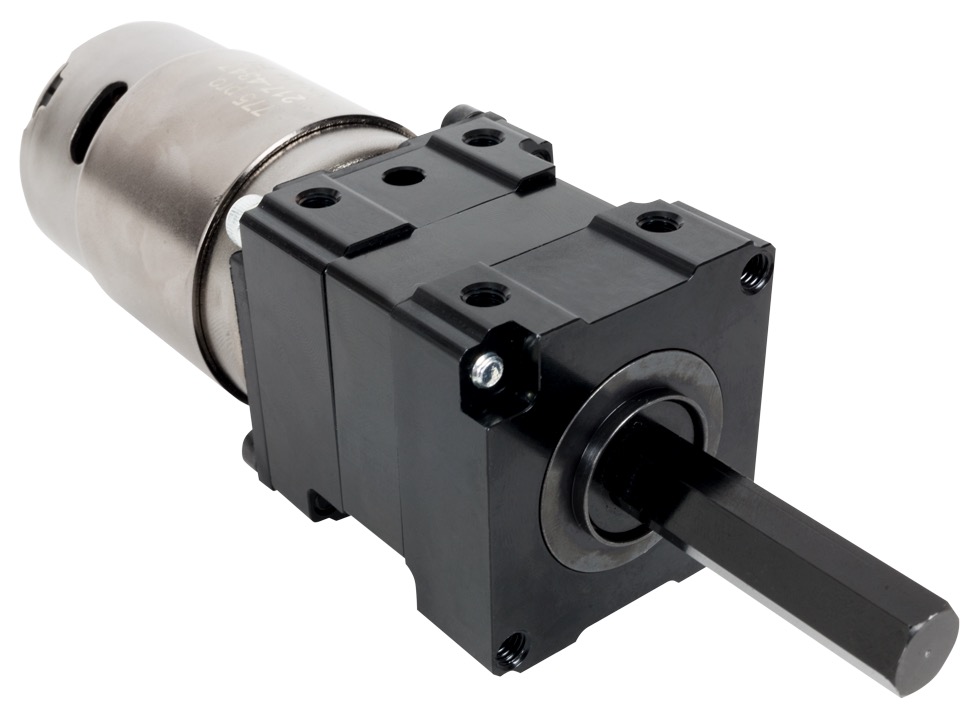
My good friend who was in FIRST robotics recommended I check out the VEX Robotics website, and it wound up being great! I was worried about finding the right motor, since I thought my specs weren't realistic due to not knowing much about motors, but I was able to find a great one that was configured to fit with a gearbox. I ordered the 775pro motor and VersaPlanetary Gearbox (to reduce the RPM from 18,730 to 700-900) from VEX.
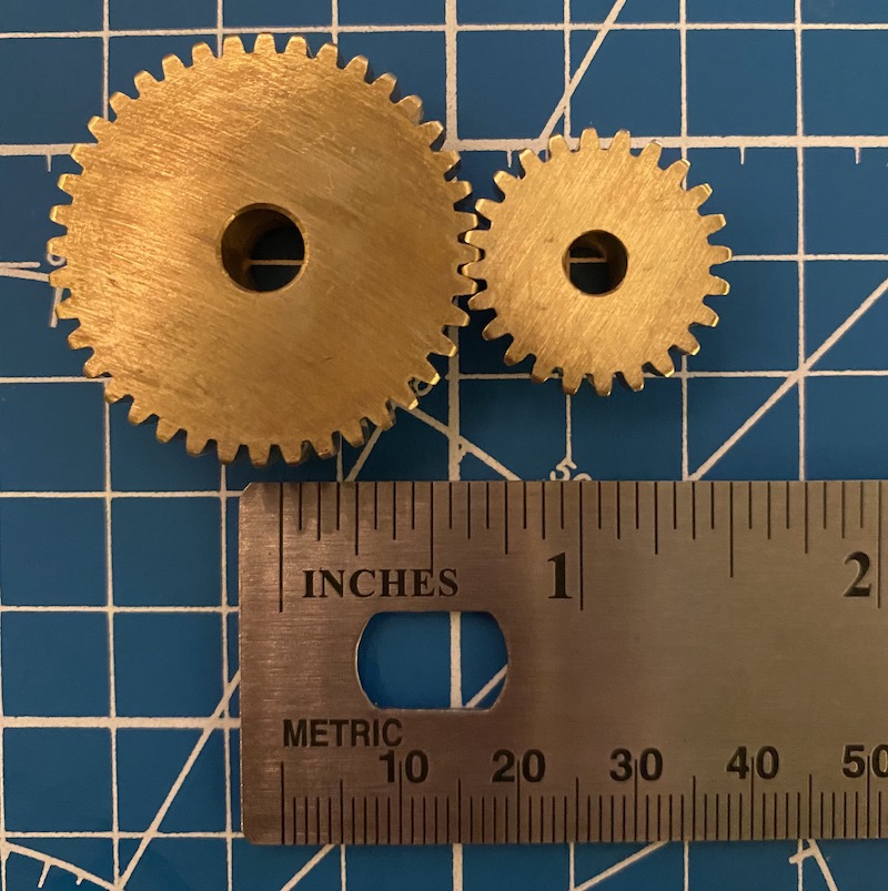
I also ordered gears from McMaster -- we had realized it would just be easier not to machine the gears. I learned to use McMaster's filters to find meshing gears, but ordered ones that were too small (the distance between the centers should be 2 in), so I'll be returning them.
Details - 11/29 to 12/1
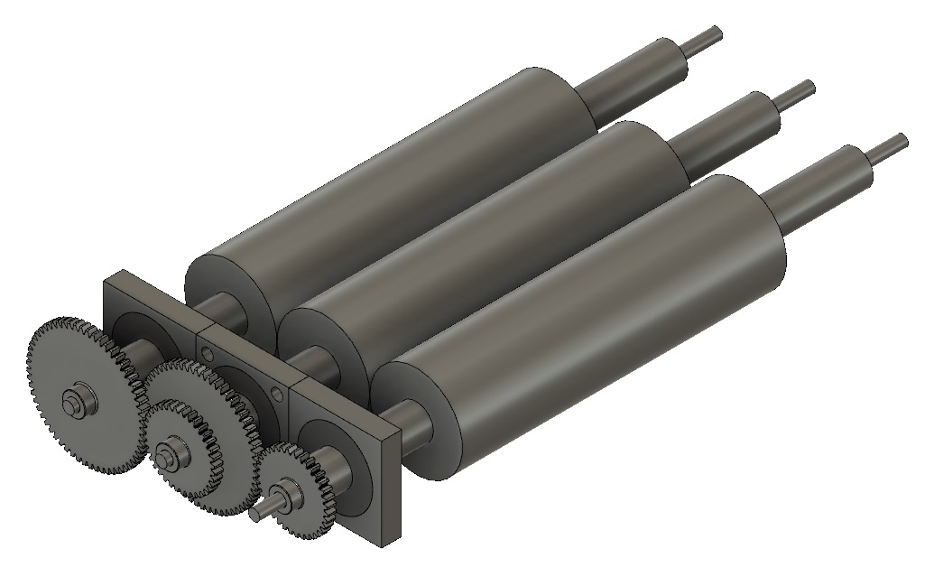
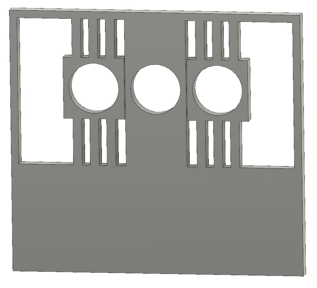
I found gears that worked and inserted them into my CAD; then I added a step-down in radius to my rollers and assembled the bearings and bearing blocks to get an idea of what everything would look like. I'm going to talk to Dan to see what he thinks of the gear orientations.
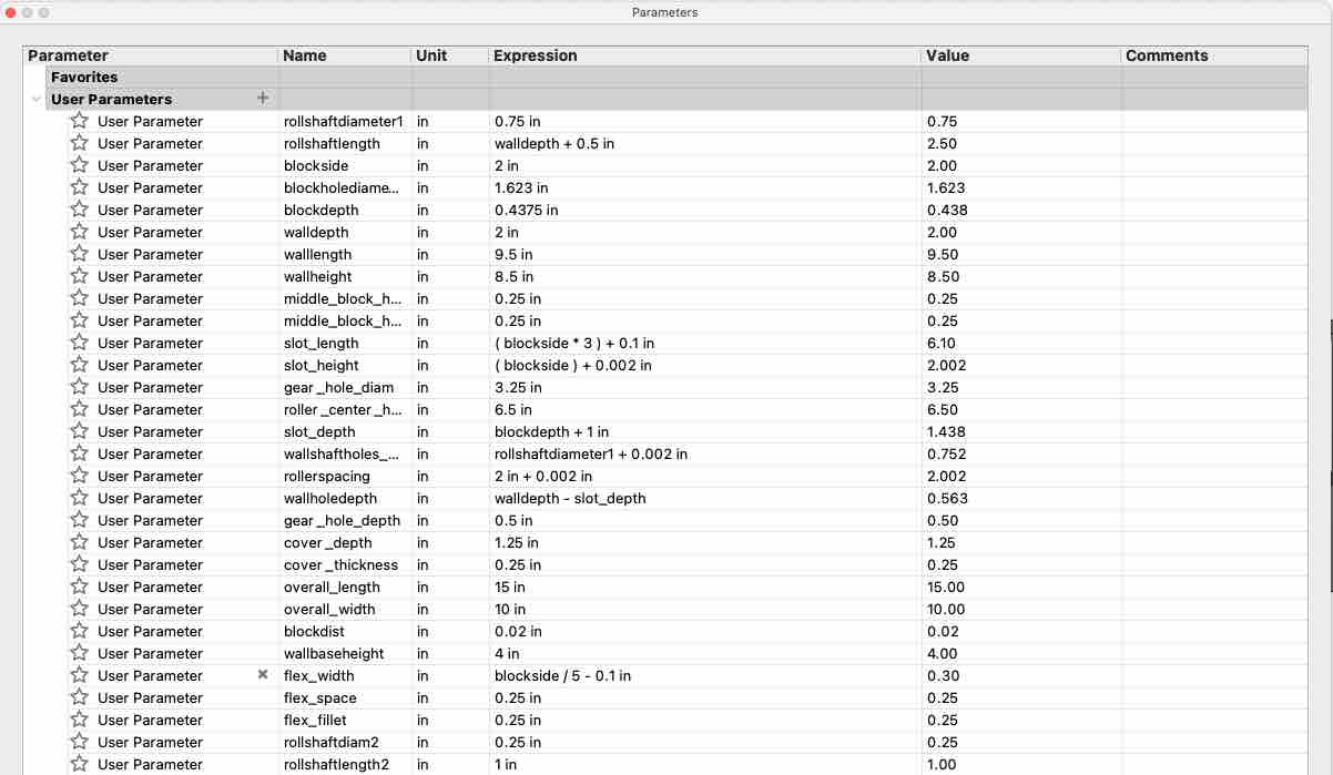
Here's how many parameters I have at this point in the CADing process!
Dominic suggested that I use a flexure plate instead of bearing blocks with tensioning springs; this will avoid slop when the blocks slide in the slot and allow for small adjustments. The adjustment knobs will push on the blocks in the plate, and they'll displace horizontally.
I need to make the thin flanges thinner, add radii to the sharp edges, and make the bounding box thicker. Also add in parts for the adjustment knobs.
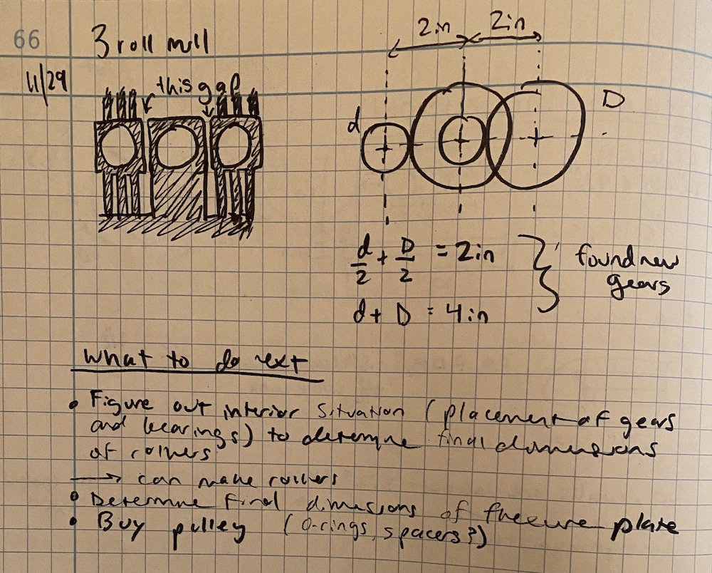
Some notes on ordering new gears, the flexure plate, and my next steps.
More CAD - 12/1 to 12/4
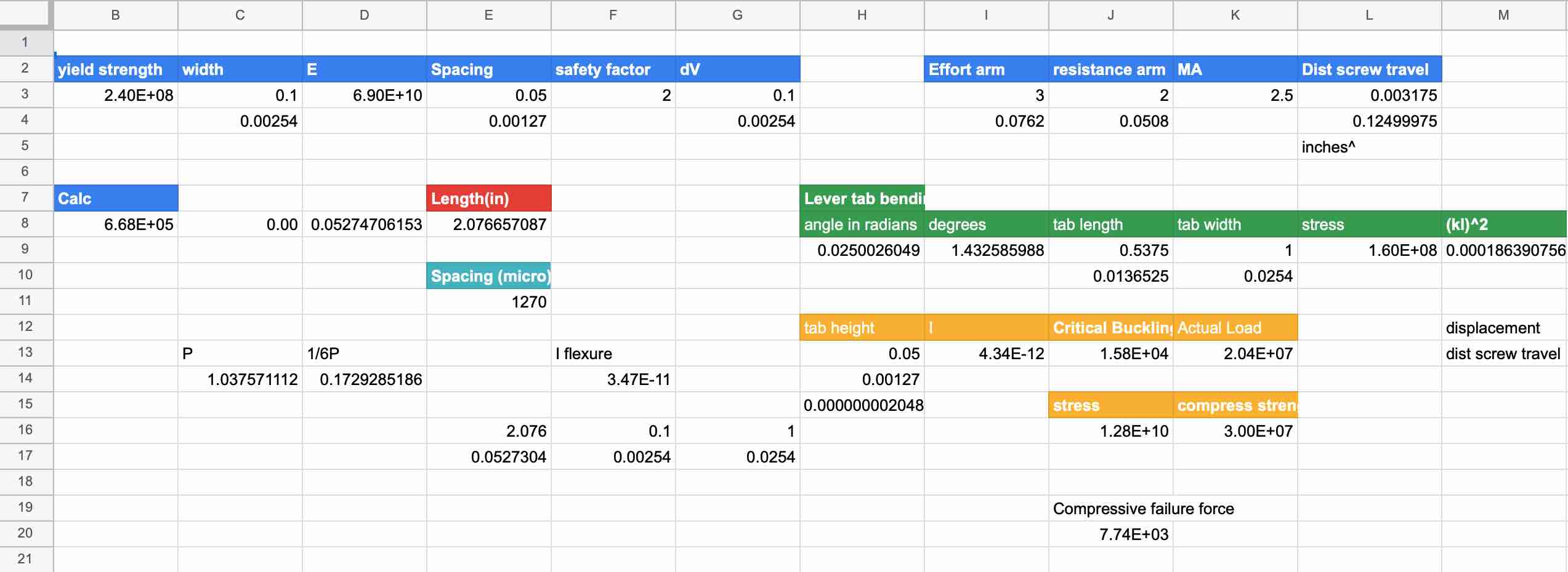
I wound up doing a ton of calculations to determine the thickness and length of each beam in my flex plate so that they wouldn't buckle, bend, or break. Initially, I had been calculating beam bending and such in my notebook by hand and with a
calculator, so transitioning to Google Sheets was incredible for how much faster and more efficient it was to tweak all my variables.
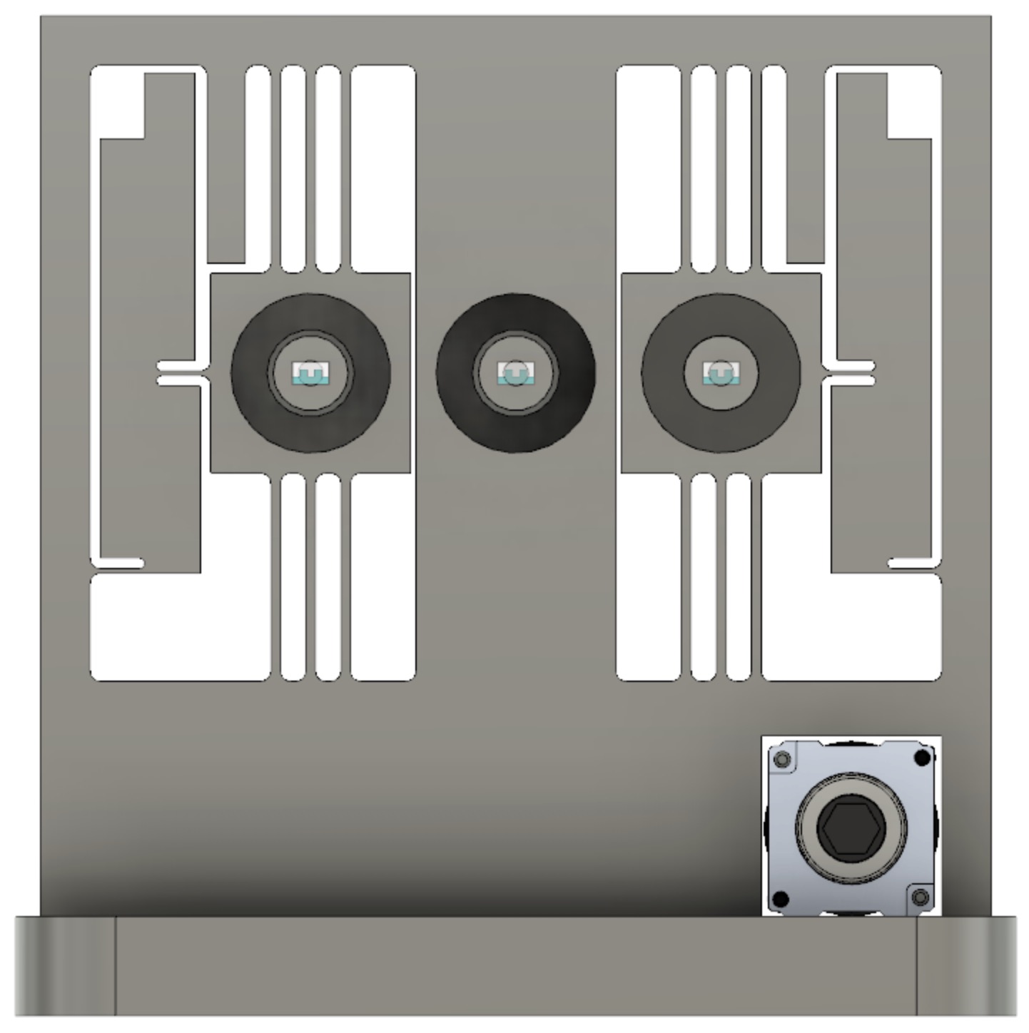
Here's my flex plate after calculations and adjustments. The funky looking parts on the left and the right are the adjustment levers. I'll turn a knob at the top of the lever, which will
push the bearing block inward, allowing fine-tuning of the gap between the rollers. I used a mechanical advantage of 2.5, which means the bearing block will travel a lesser distance than the screw. If the user
turns the screw so that it displaces .25 in, the block will move .1 in.
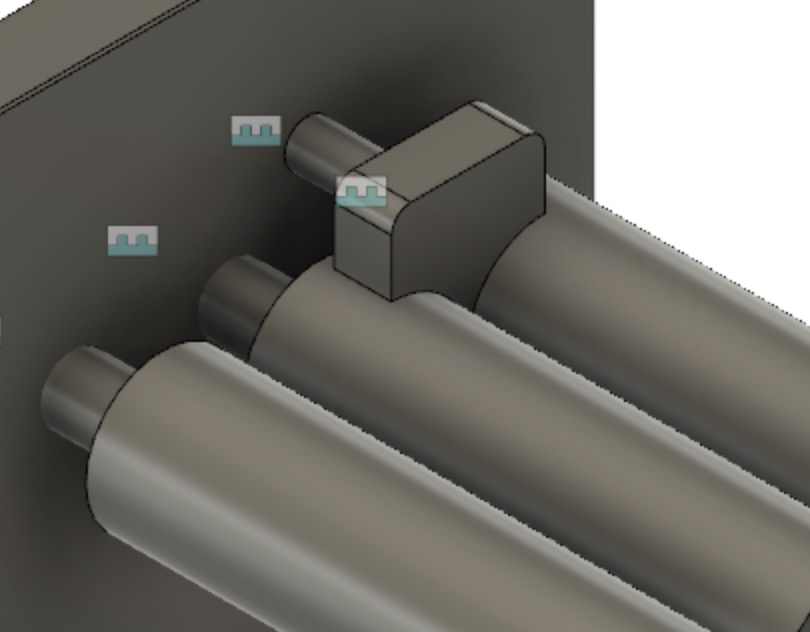
I also added an inner plate to protect the flex plate and internal components. The roller shafts go into slots that are slightly bigger so that they aren't resting on the plate.
A detachable guide slides into a tube on the inner plate; the guide sits on the rollers and keeps the paint from going too far to the side.
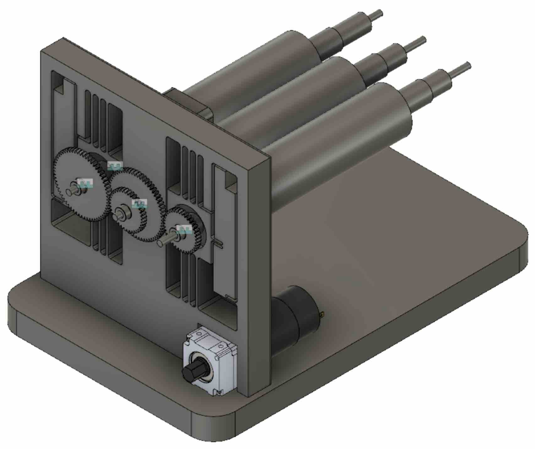
And here's the CAD as of final presentations. I didn't design the scoop or the cover for the electronics, since I decided those were
less critical than the other components. The goal: have at least one roller spinning and the flex plates attached to the baseplate.
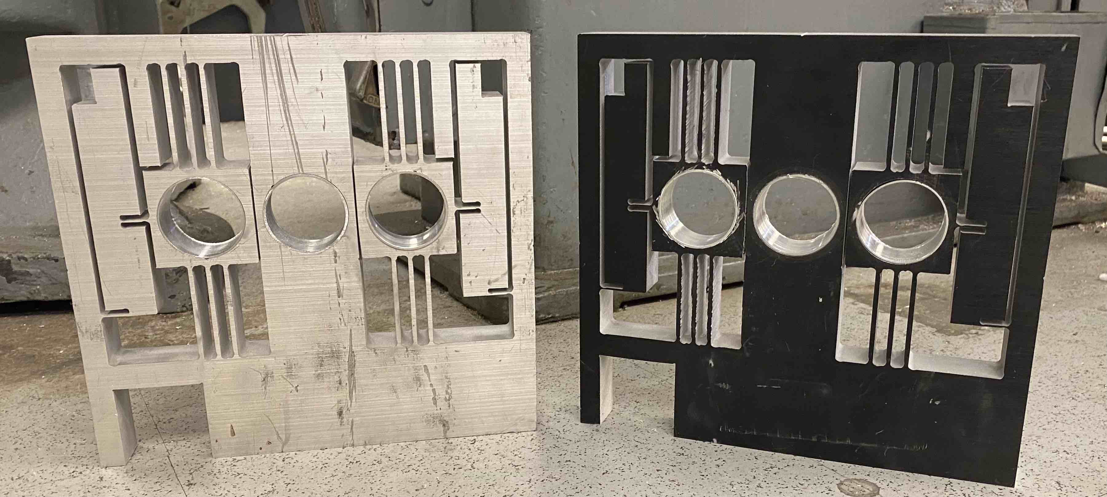
Waterjetting Flexure Plate - 12/4
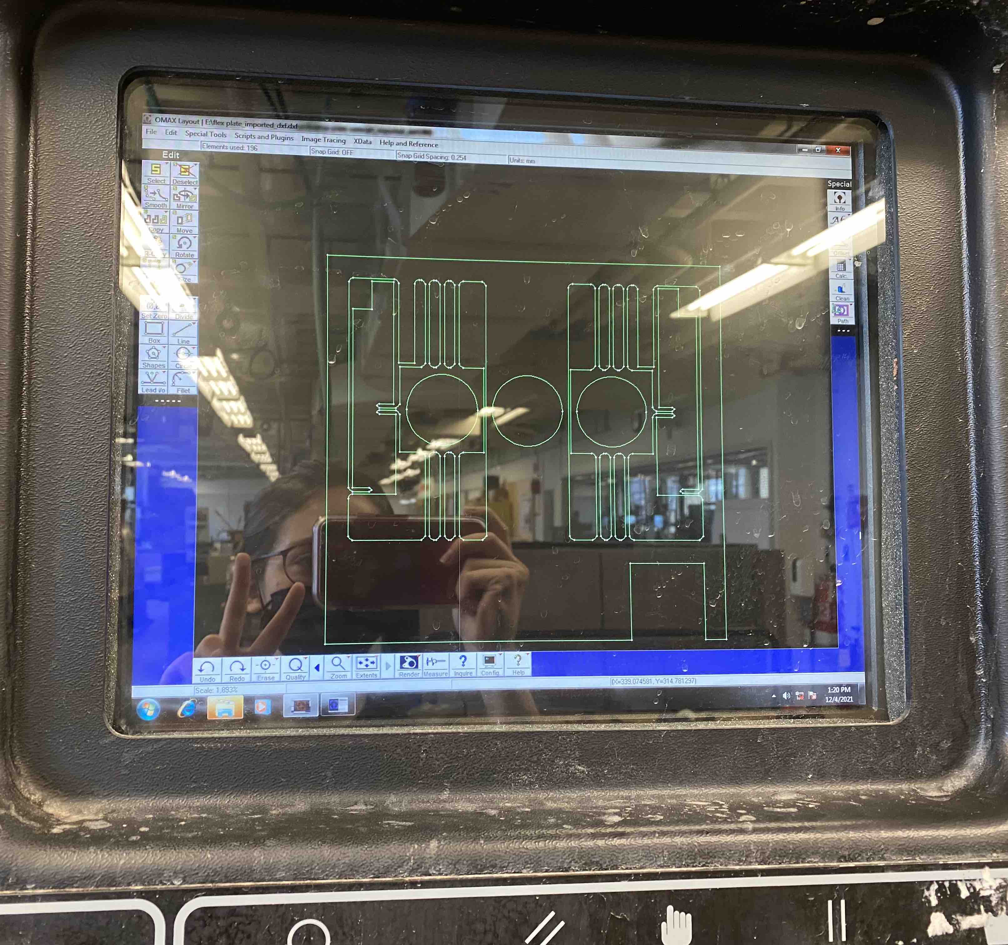
After transfering a .dxf version of the flex plate to the LMP's OMAX Waterjet, I created the cutting toolpath in OMAX Layout.
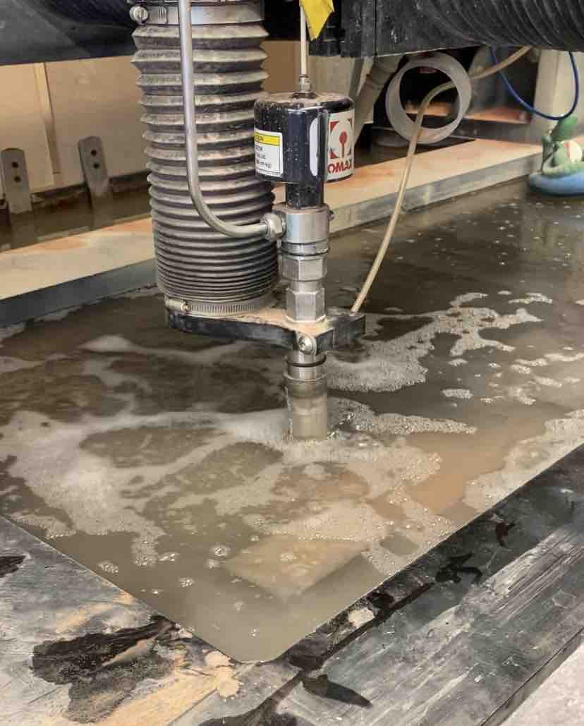
Waterjetting the flex plate from 1 in thick aluminum.
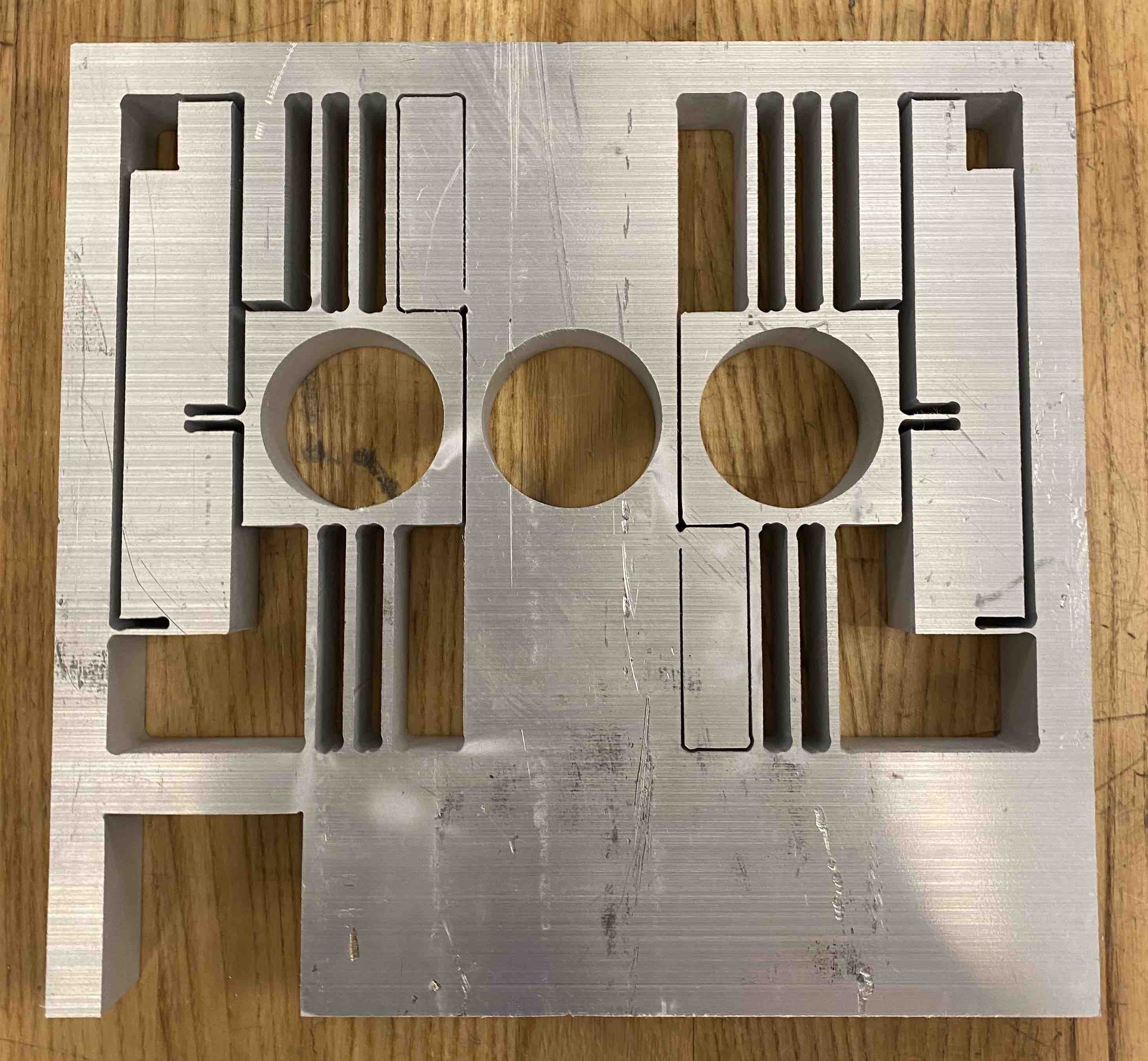
And here it is! For some reason, the waterjet didn't cut all the way through certain holes. This also happened on the other flex plate (but because I ran out of garnet and didn't notice). To fix this, I used a dremel to cut the remaining blocks and a hammer to tease them out. The second plate (not shown) got a bit beat up by the waterjet running without garnet, so it looks pretty rough (dremeling didn't help).
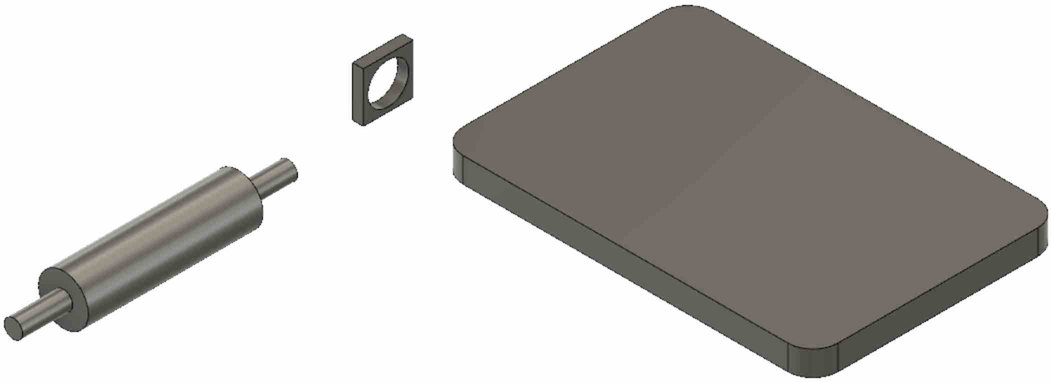
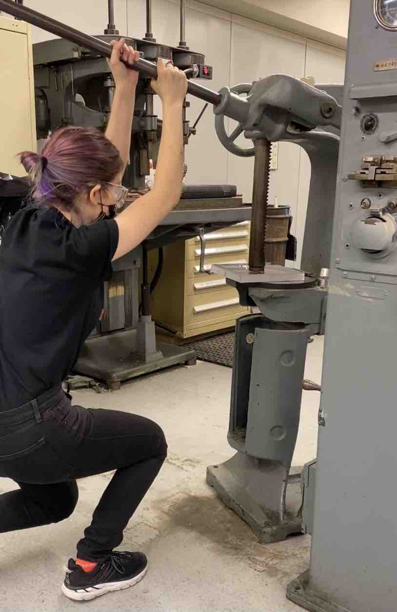
Turning Roller Shafts - 12/9 - 12/11
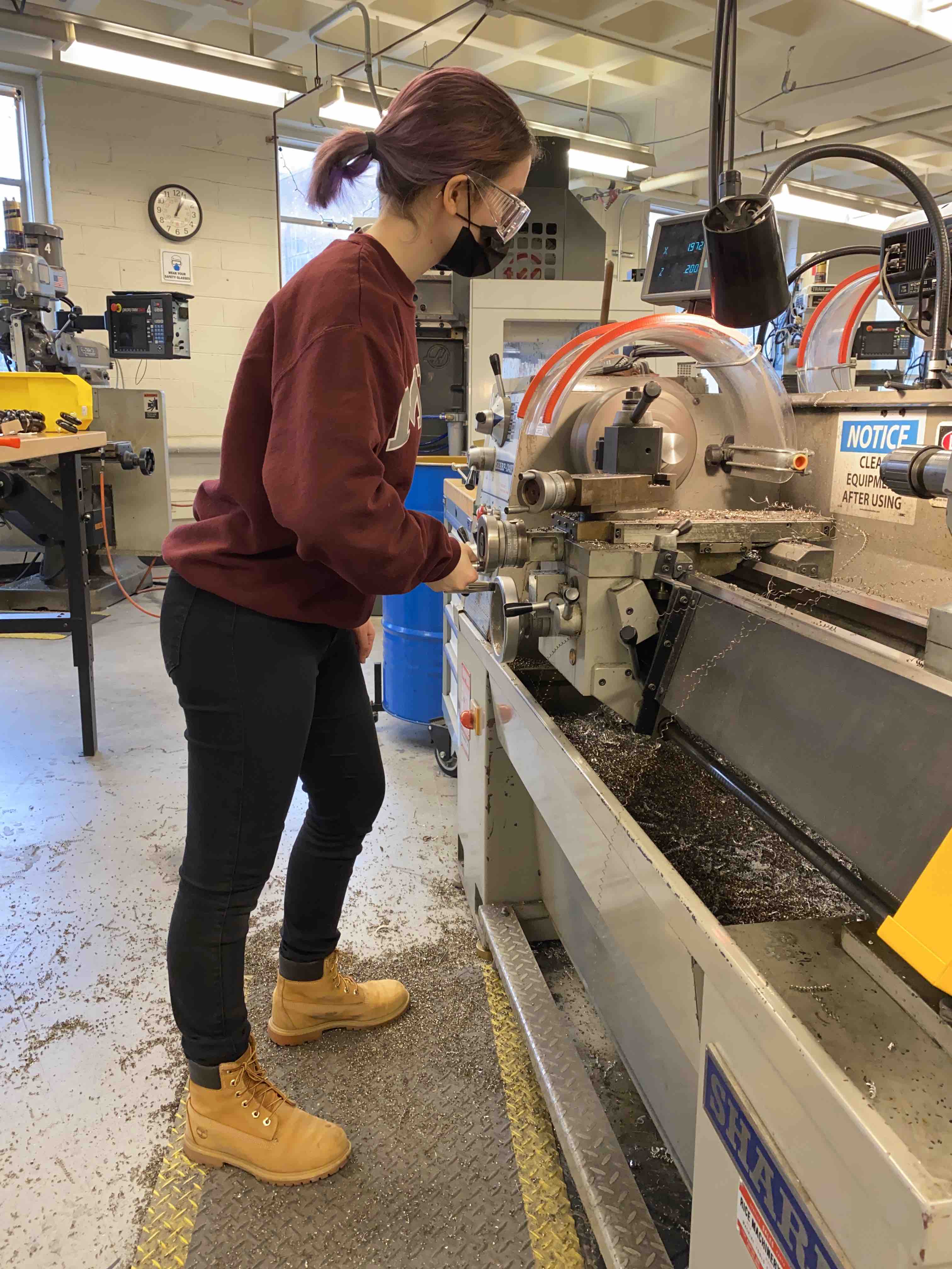
Jen helped me order 3 ft of stainless steel pipe for the rollers. I chose pipe instead of solid stock so that the rollers (and whole machine) would be lighter, since
I envisioned this mill as something I could carry. To make shafts for the rollers, I turned down solid stock to press fit (with a bit of clearance) into the rollers, which would align them before welding it all into one piece.
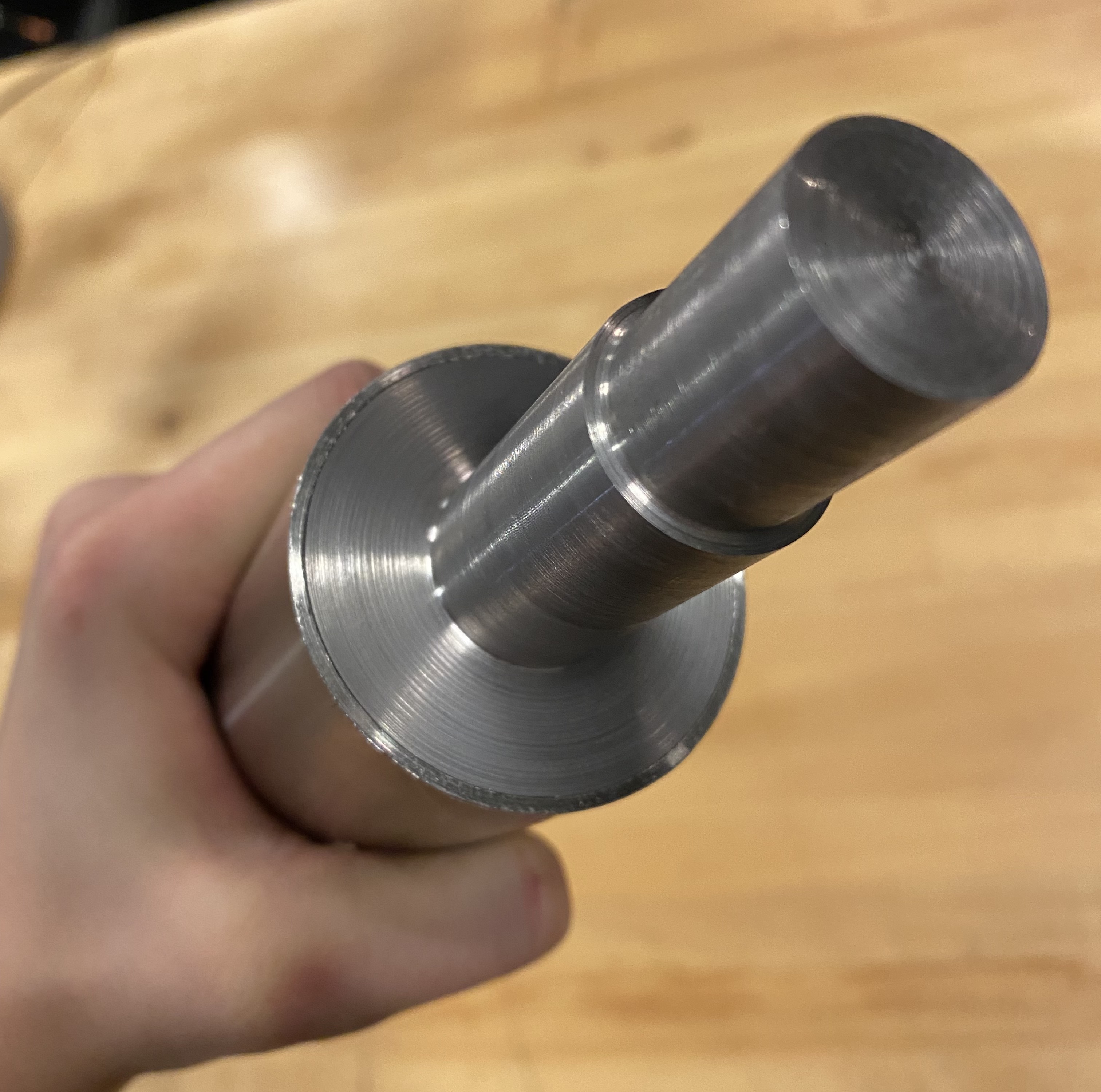
We only had 2.25 in diameter stock, so I had to turn down a lot.
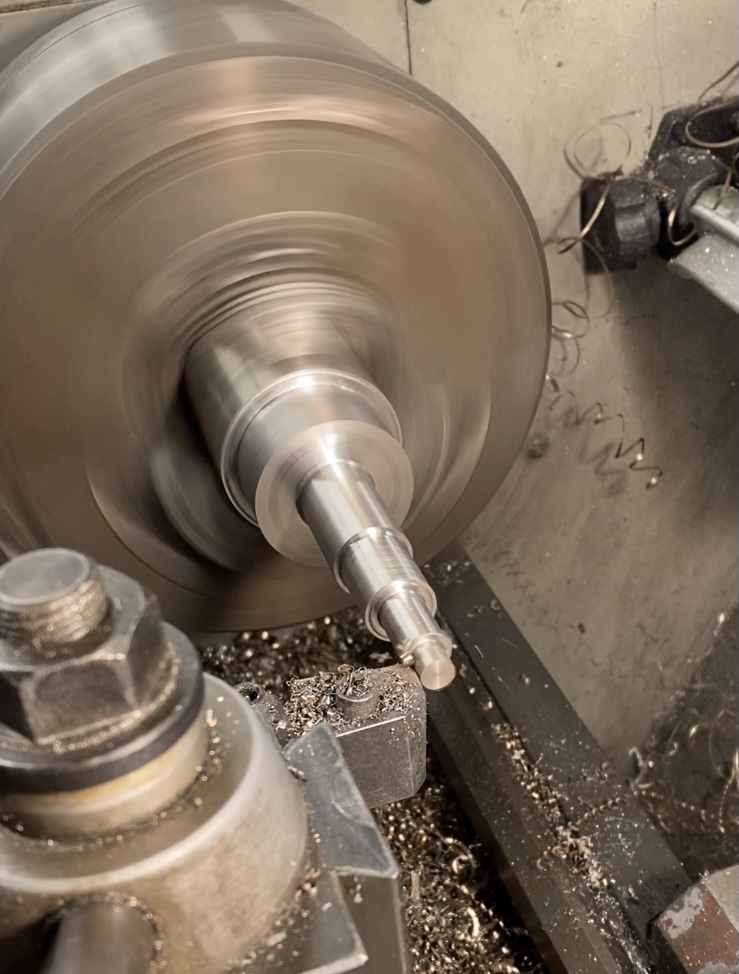
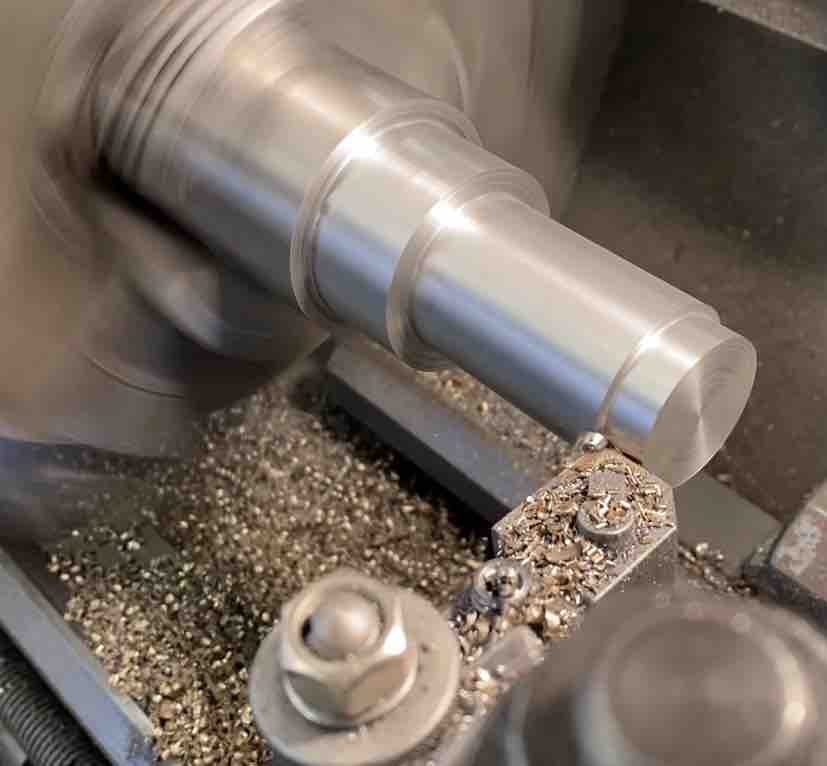
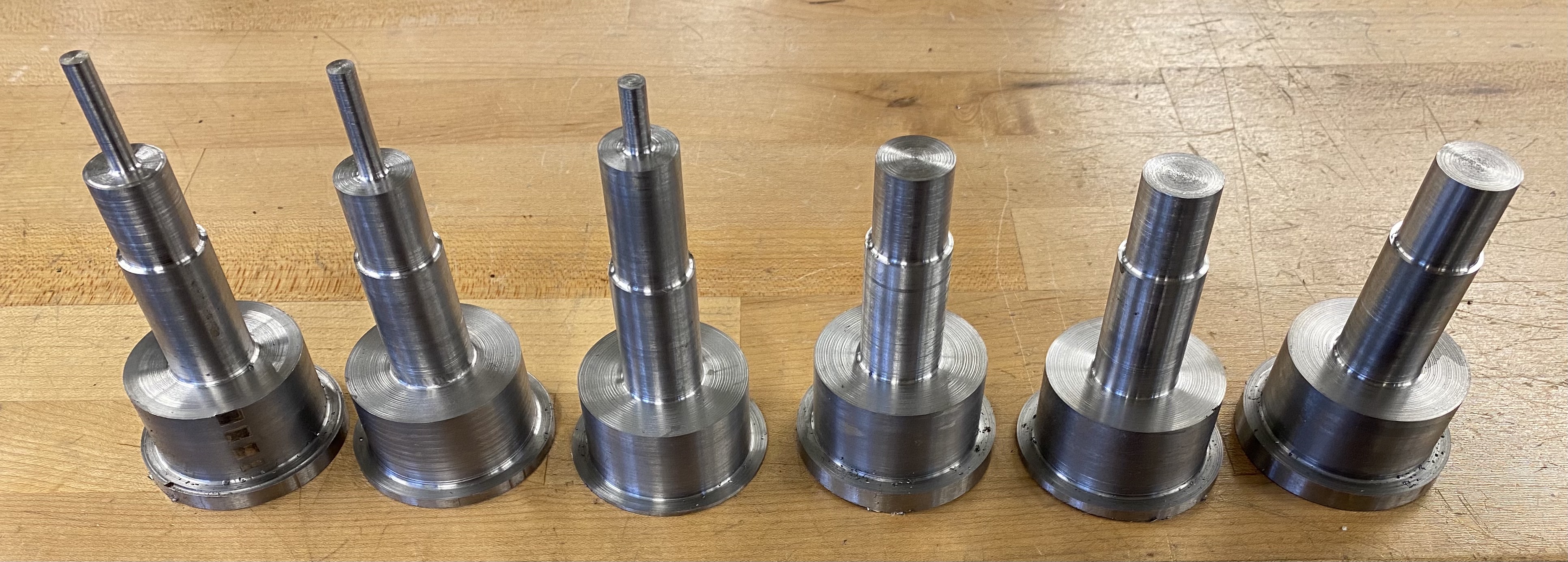
Several step-downs on the shafts ensure the rollers align in the bearings and stay in place, and the gears align. I had to be pretty careful with turning down to the right size
so that my bearings could press fit on.
And the gears spin! I didn't have to worry too much about the gear fit since they'll lock on through set screws.
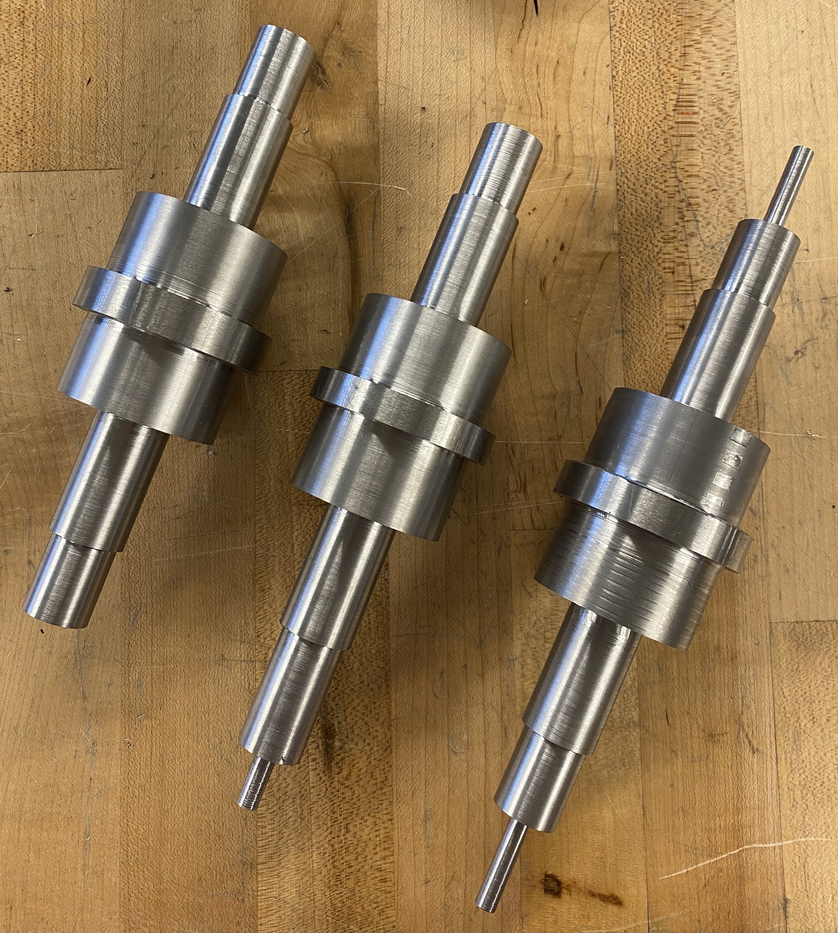
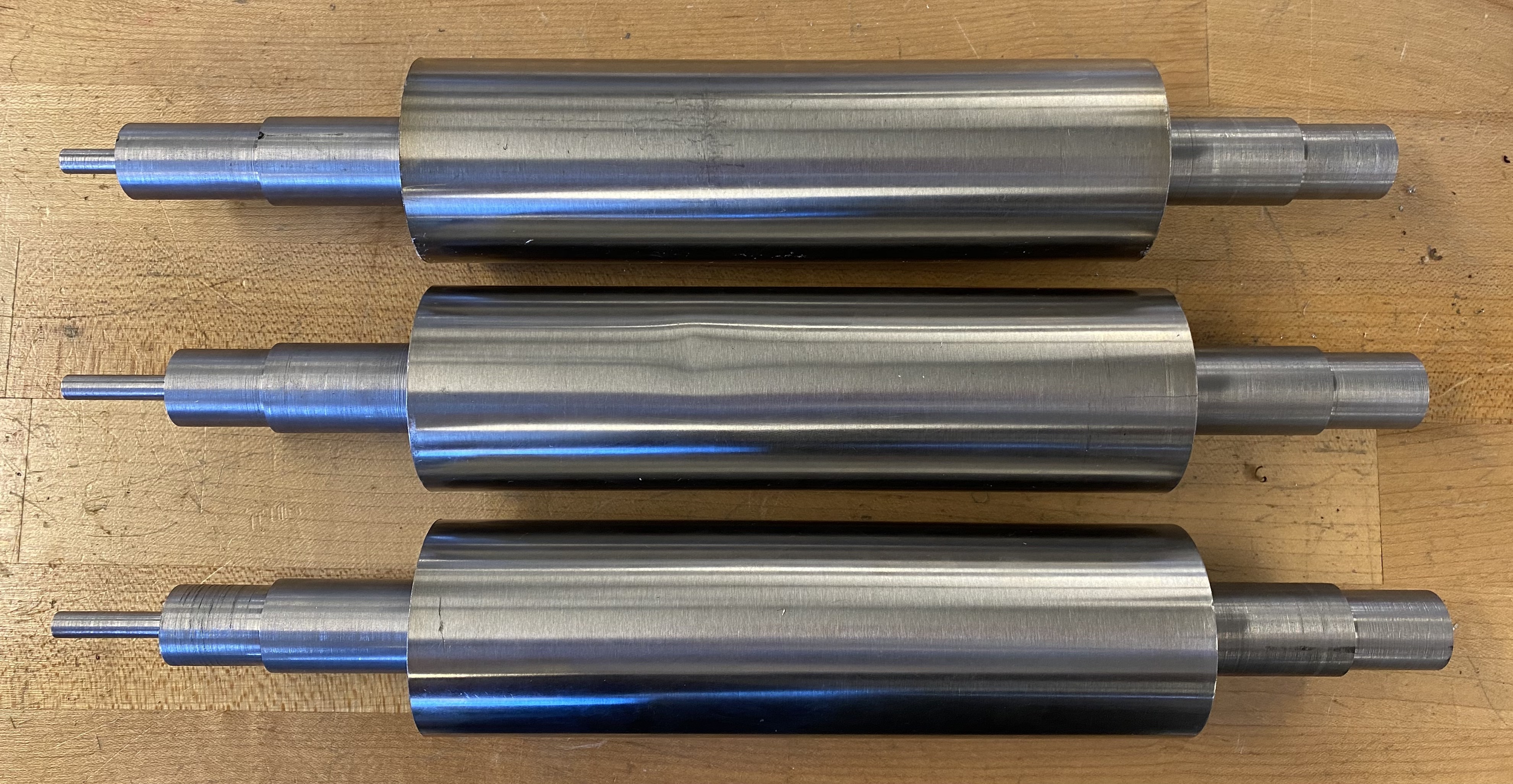
The shafts all turned down. I made two shafts on each bit of stock to save on material. To protect the shafts when clamped, I wrapped a snippet of brass sheet around them so the jaws of the
lathe wouldn't produce clamp marks.
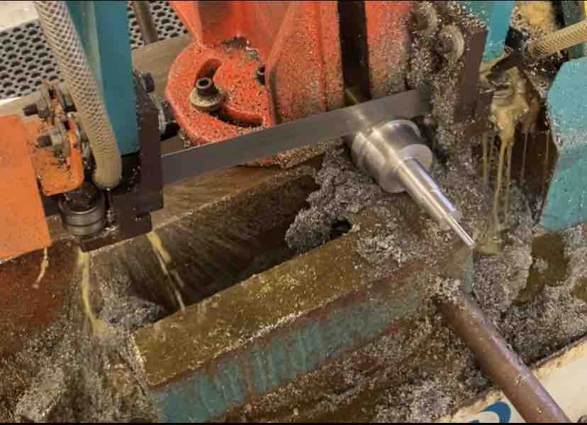
Choppin' the shafts apart on the horizontal bandsaw.
Shafts all cut apart.
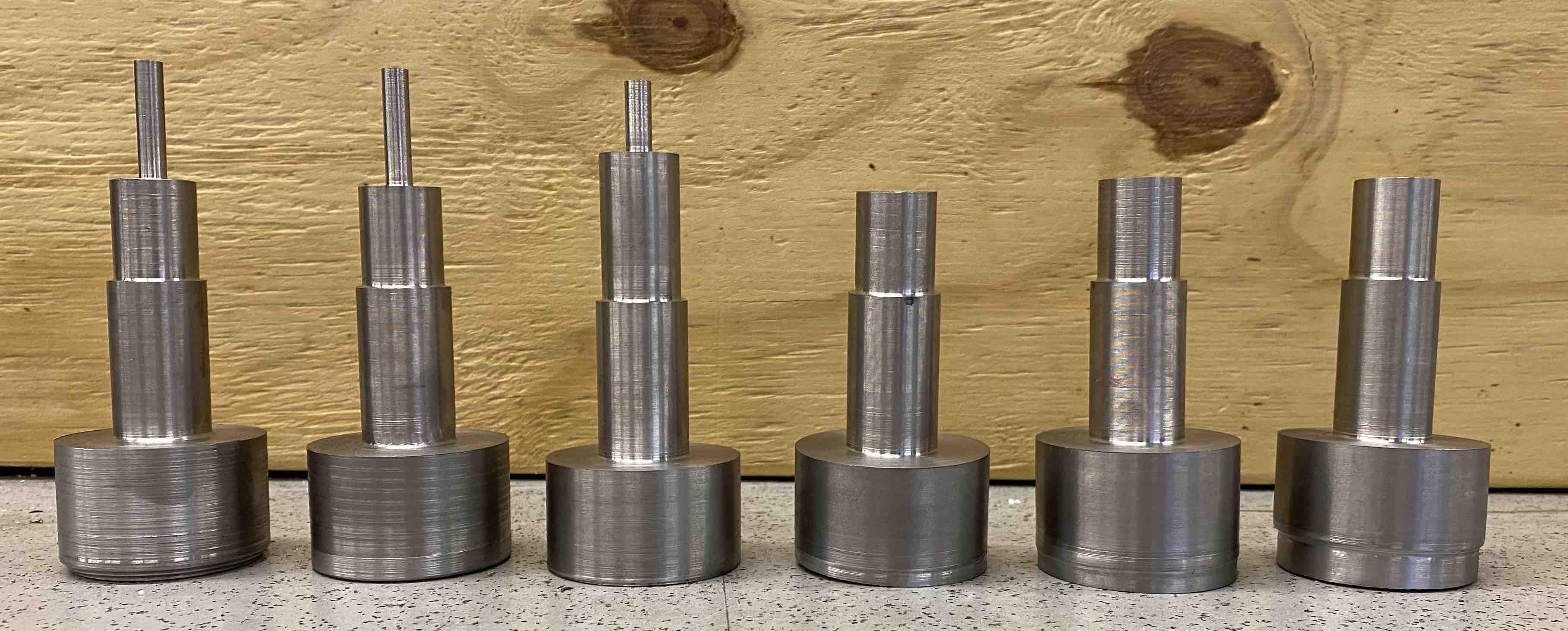
Shafts after turning down the extra material on the end.
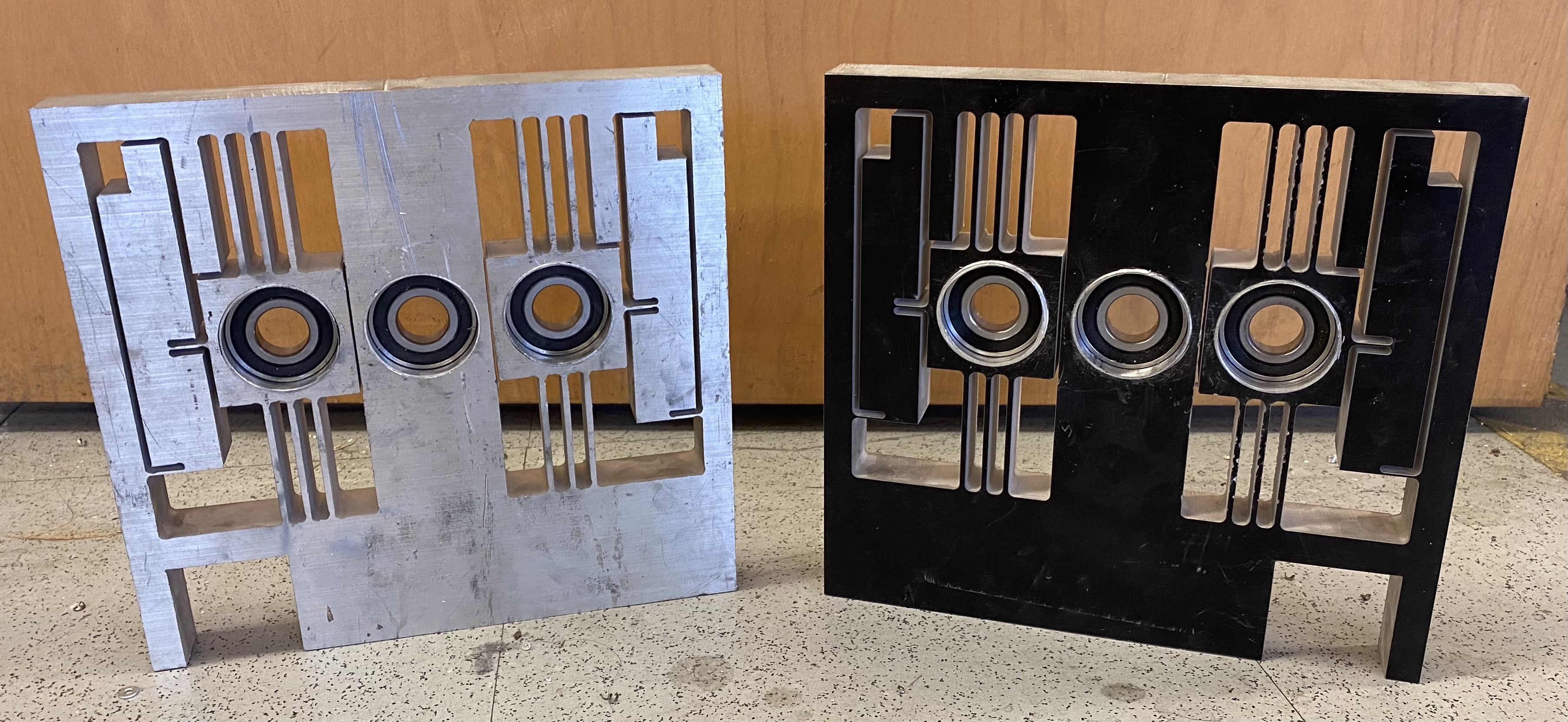
Flexure Plate and Bearings - 12/11 - 12/12
The waterjet doesn't cut straight down, but instead at a slight angle. To ensure the bases of the flex plates were smooth, I milled a tiny bit off the bottom. I also bored out the bearing holes.
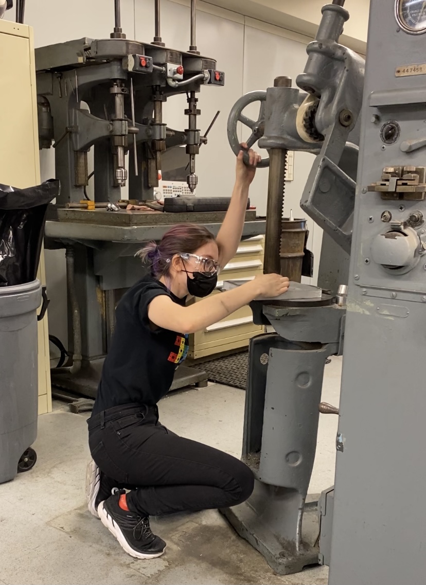
Six hours of turning produced six rings to shim the bearing holes, since when I had adjusted the diameters through parameters to account for clearance, I goofed up and added instead of subtracted. Here I am pressing the rings into the flex plates.
This was pretty fun!
And here are the flex plates with the rings inside!
Electronics - 12/6 - 12/13
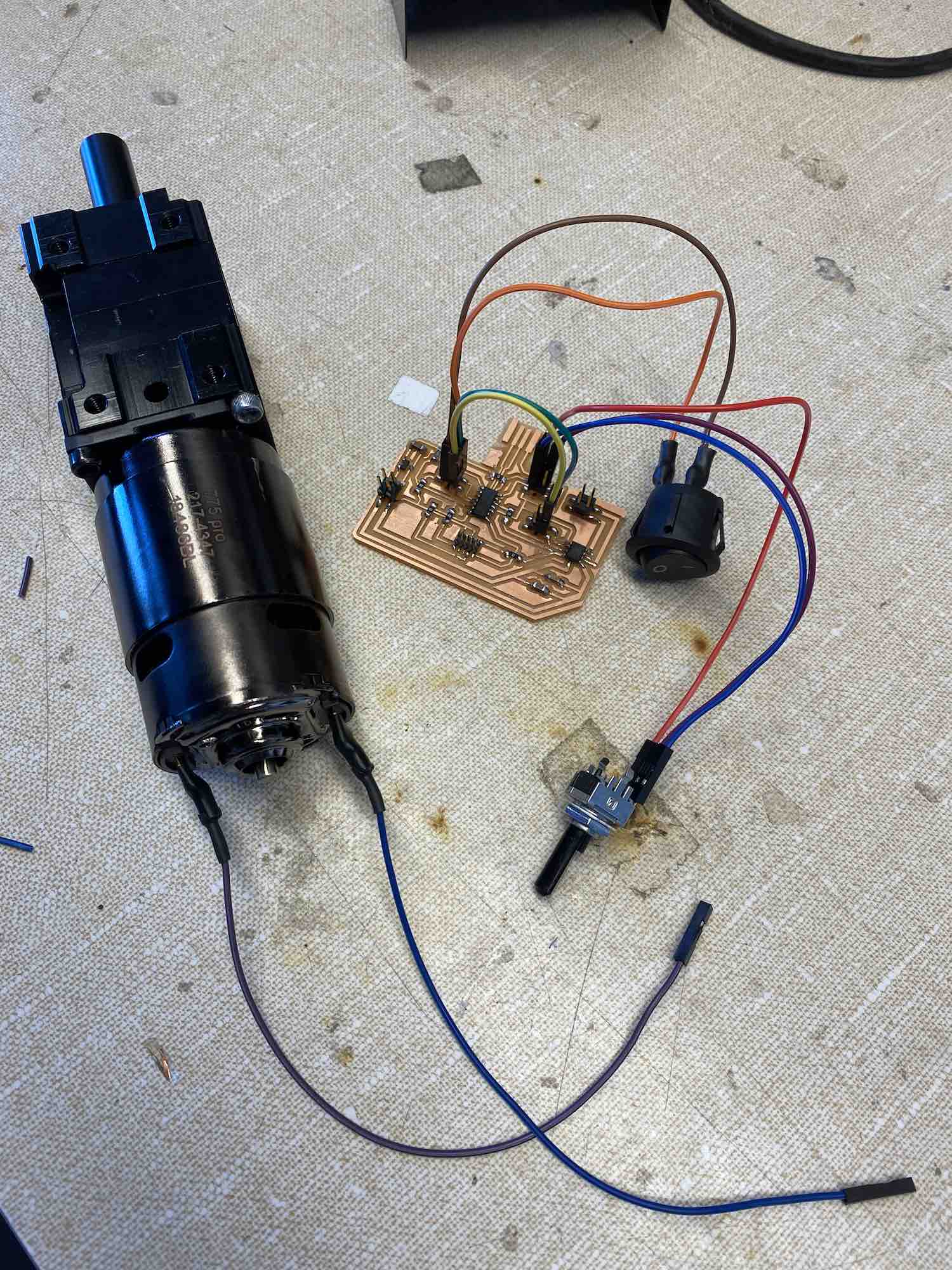
When the LMP wasn't open this week, I spent time on the electronics. I adapted my motor board from output devices week (Week 10) by adding a switch and a couple more headers so I
wouldn't have to solder wires directly to the board. I milled the board with both of the Arch Shop's remaining 1/64 endmills, and discovered both had broken since the traces were
totally misaligned and butchered. After a third milling with a good endmill, the board was all set for soldering. I then soldered the ends of jumper wires to my switch, potentiometer, and motor and used
heat shrink to make it look nice and keep everything in place.
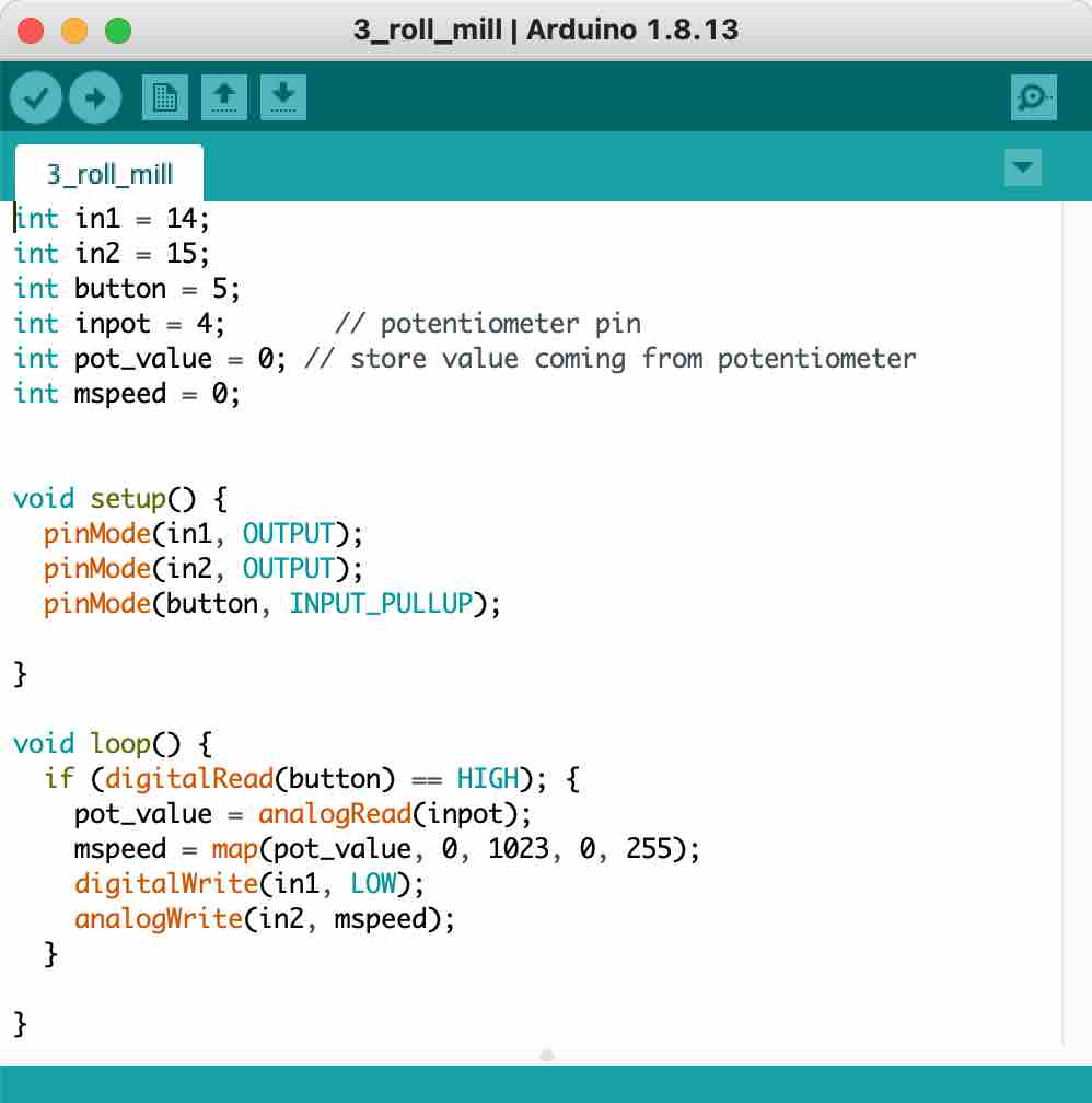
Here's my Arduino code. When you turn on the switch, then you can use the potentiometer to control the motor speed. This prevents
the motor from starting as soon as you plug in the power source, allowing finer control and also providing an on/off function.
Misc 12/12
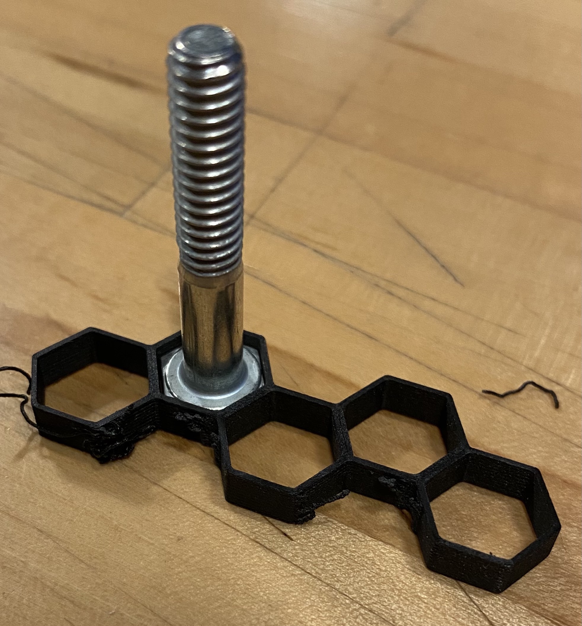
With the LMP closed early on Sunday, I turned to what I could do elsewhere. To make the handles for the adjustment mechanism, I first measured
the screws I planned to use, and then I made a tolerance test print. I made several hexagons, differing by two thou plus or minus from the measured dimension. After printing, I slid the screw into the hexagonal slots to see which dimension was ideal.
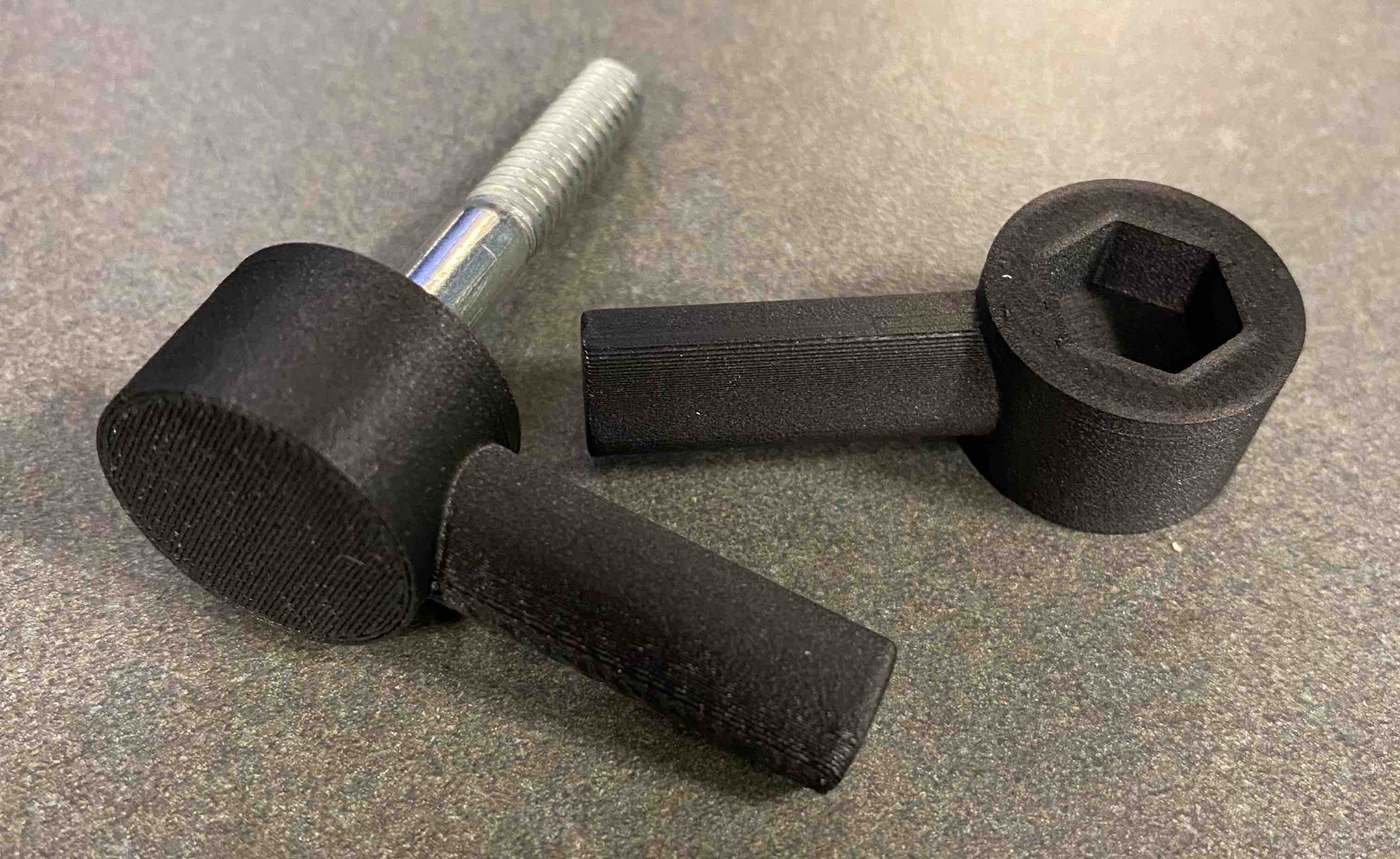
Then I printed the handle! I'll need four of these for the final machine for each of the four adjustment knobs.
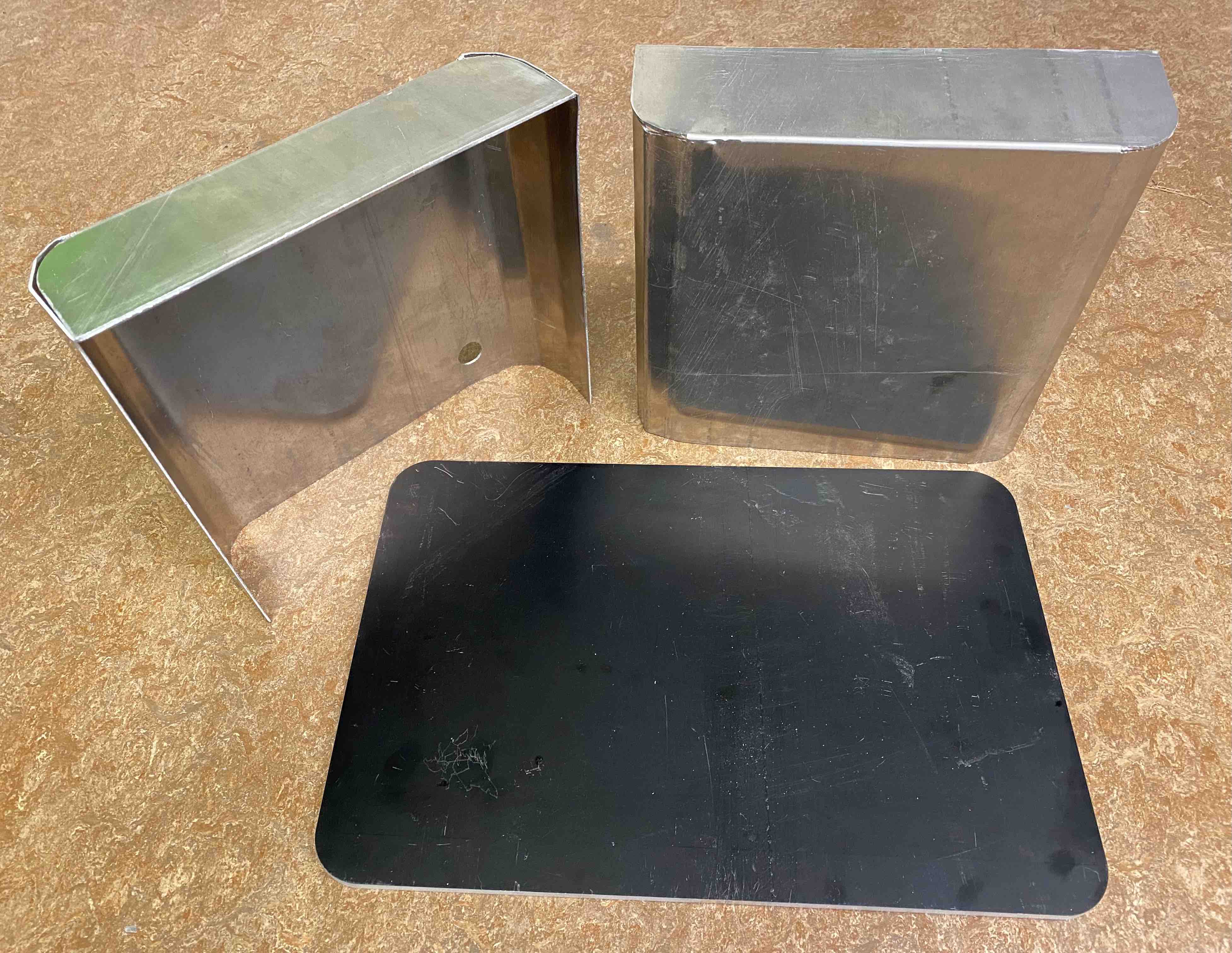
Here are some other parts I've made over the days: a baseplate waterjetted from aluminum and two covers that I bent using a metal brake.
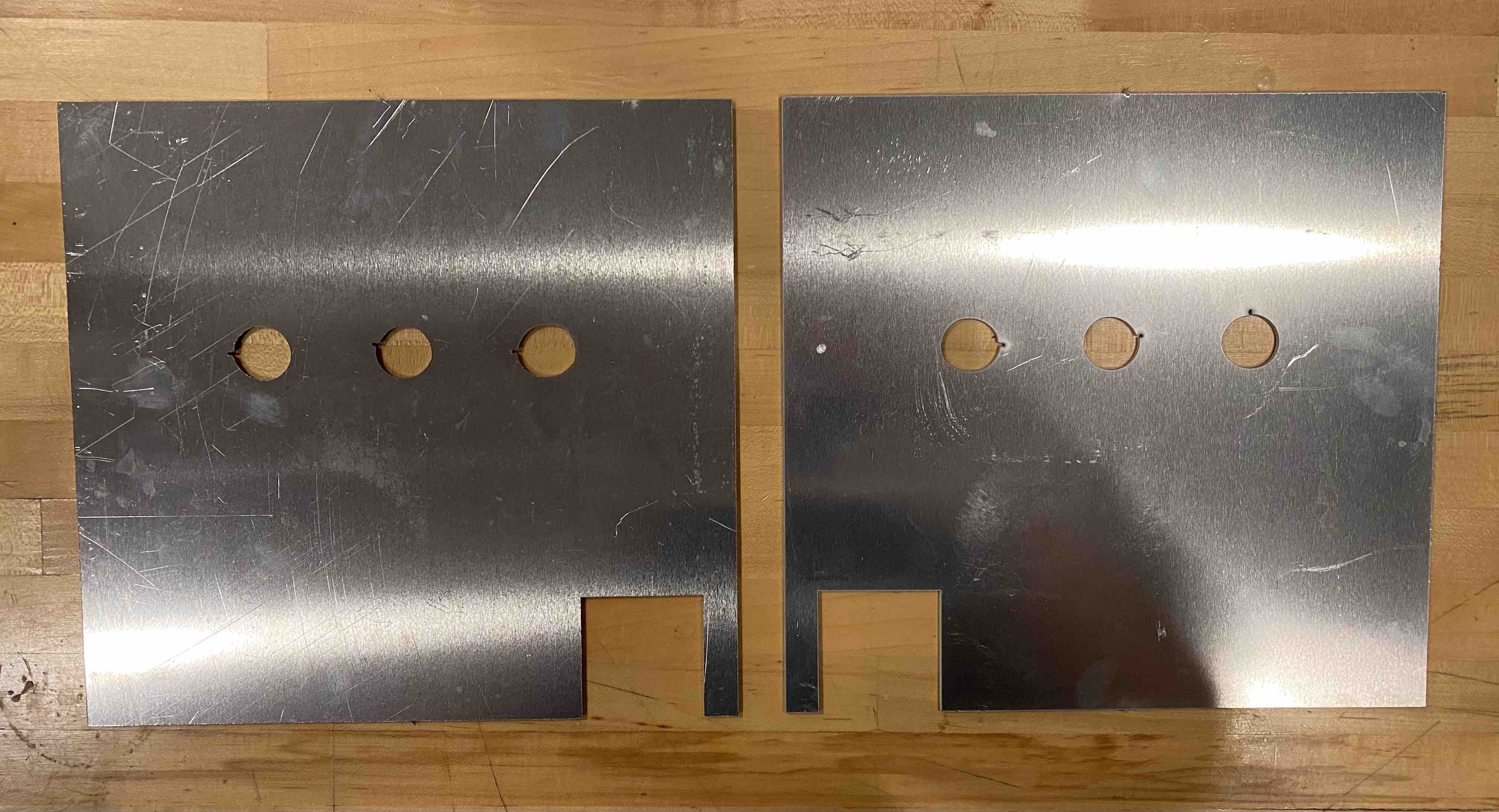
These are the inner covers -- they go along the flex plates to protect the internal components from the paint rolling area. I waterjetted them, but the holes came out
uneven because the sheet metal wasn't clamped down secure enough. That wound up being okay, since I thickened the motor shafts and have to mill the holes bigger anyway.
The day of final presentations - 12/13
I had time in the morning to go back to the LMP. The rings I had made the previous day all fit in the flex plates, but when I press fit the bearings into the rings, it was too tight. Either the
bearings didn't go in, or did go in, but didn't spin. Removing the bearings required a lot of pressing and patience. And making little cylinders to sit on top the bearings to help push them all the way through (the press was too big to fit inside). Then I
put the flex plates on the mill and bore out the rings to the diameter of my one ring-bearing couple that did spin. And then, after much more pressing and removing, finally, all bearings were spinning.
I slotted all the shafts into the rollers, which used a press/slip fit depending on the shaft.
I aligned the base of the shafts with the end of the roller. I plan to weld the shafts in place in the future.
The Final Final Project - 12/13
Here's the status of the mill as of the end of this class:
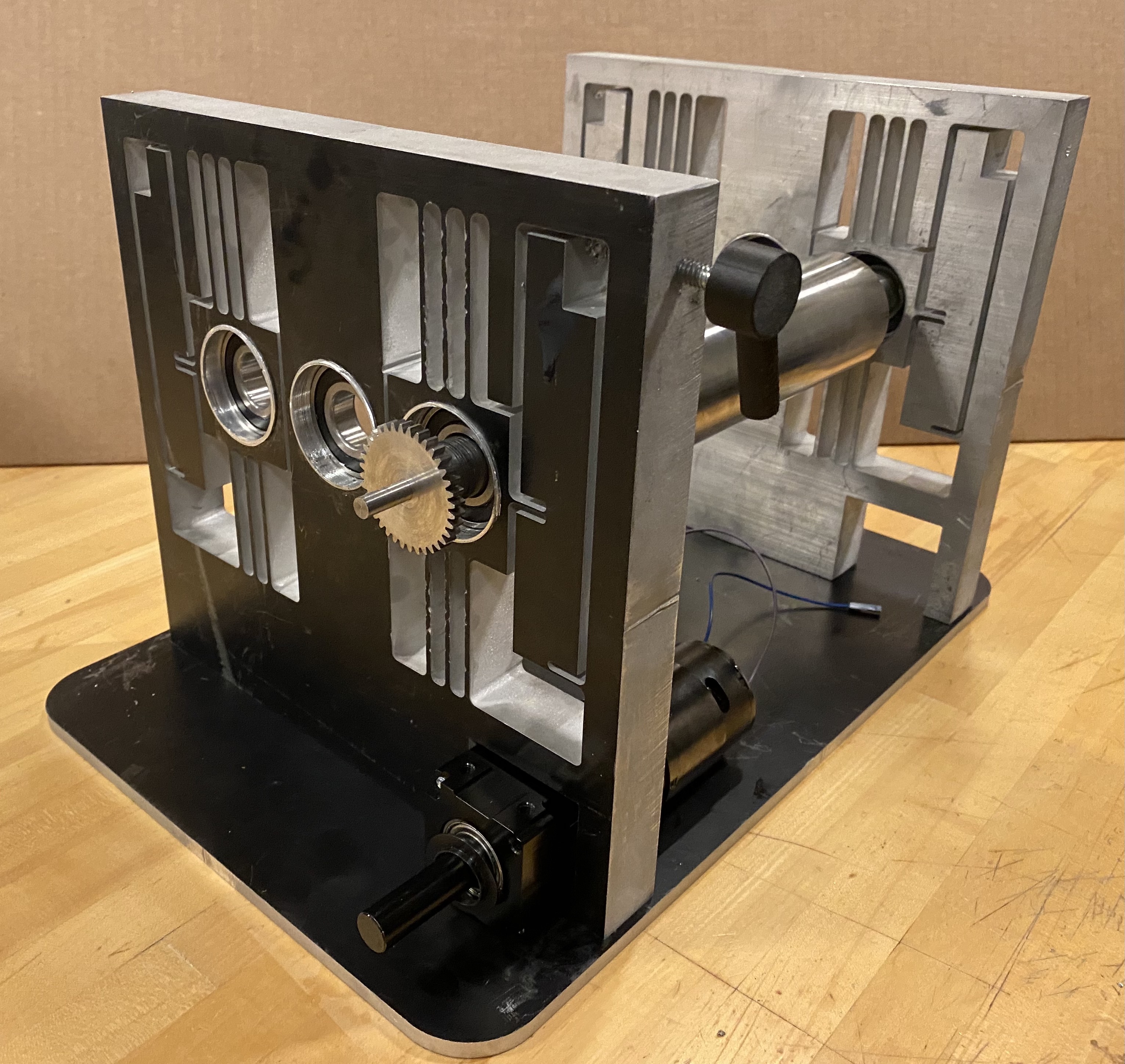
Side view of the mill without covers and electronics. I only had time to press-fit one roller into the machine, but it would've been fully operational had I
put all three rollers in! I also had ordered pulleys and a belt, but they didn't arrive in time.
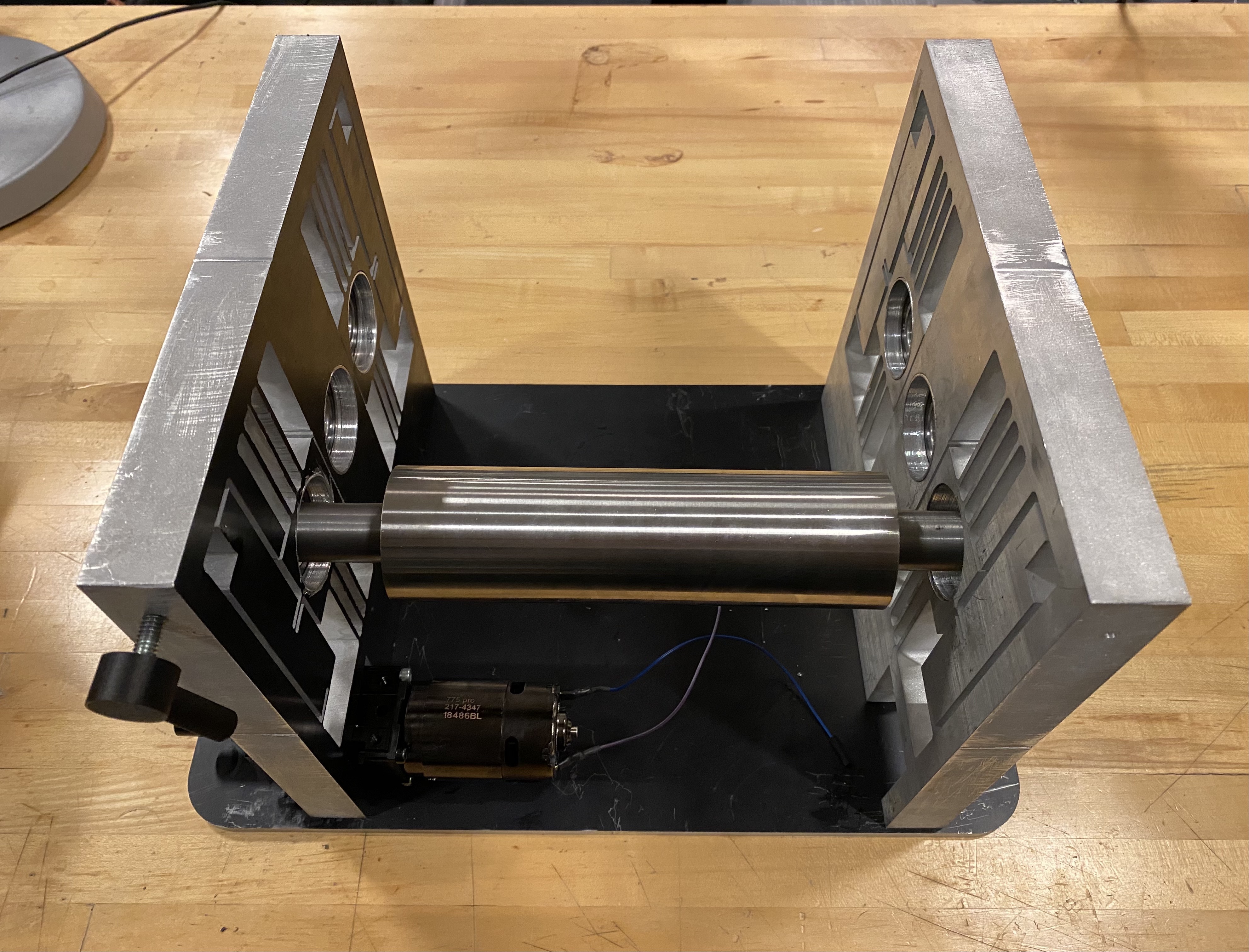
Top-down view of the skeleton of the mill.
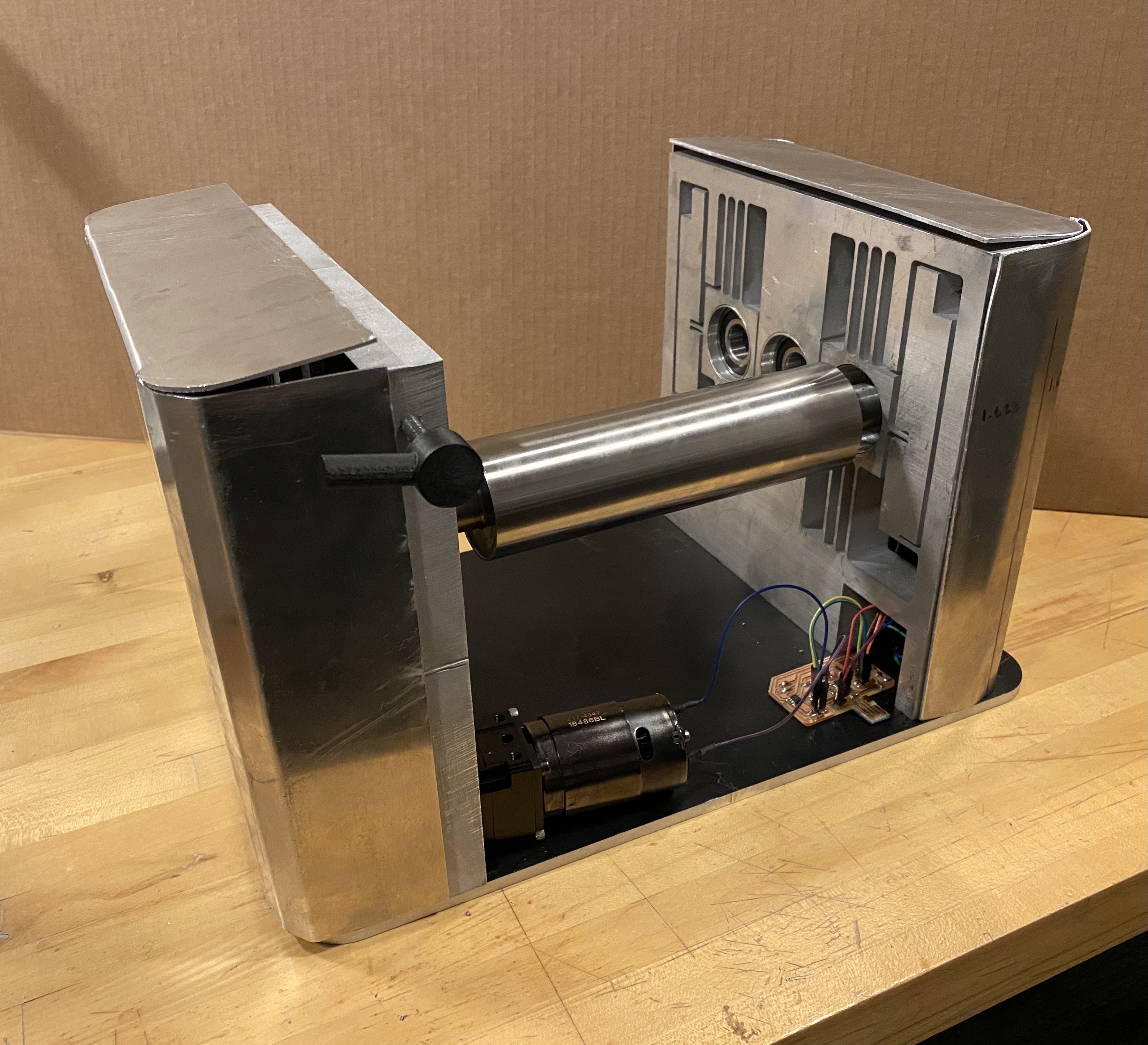
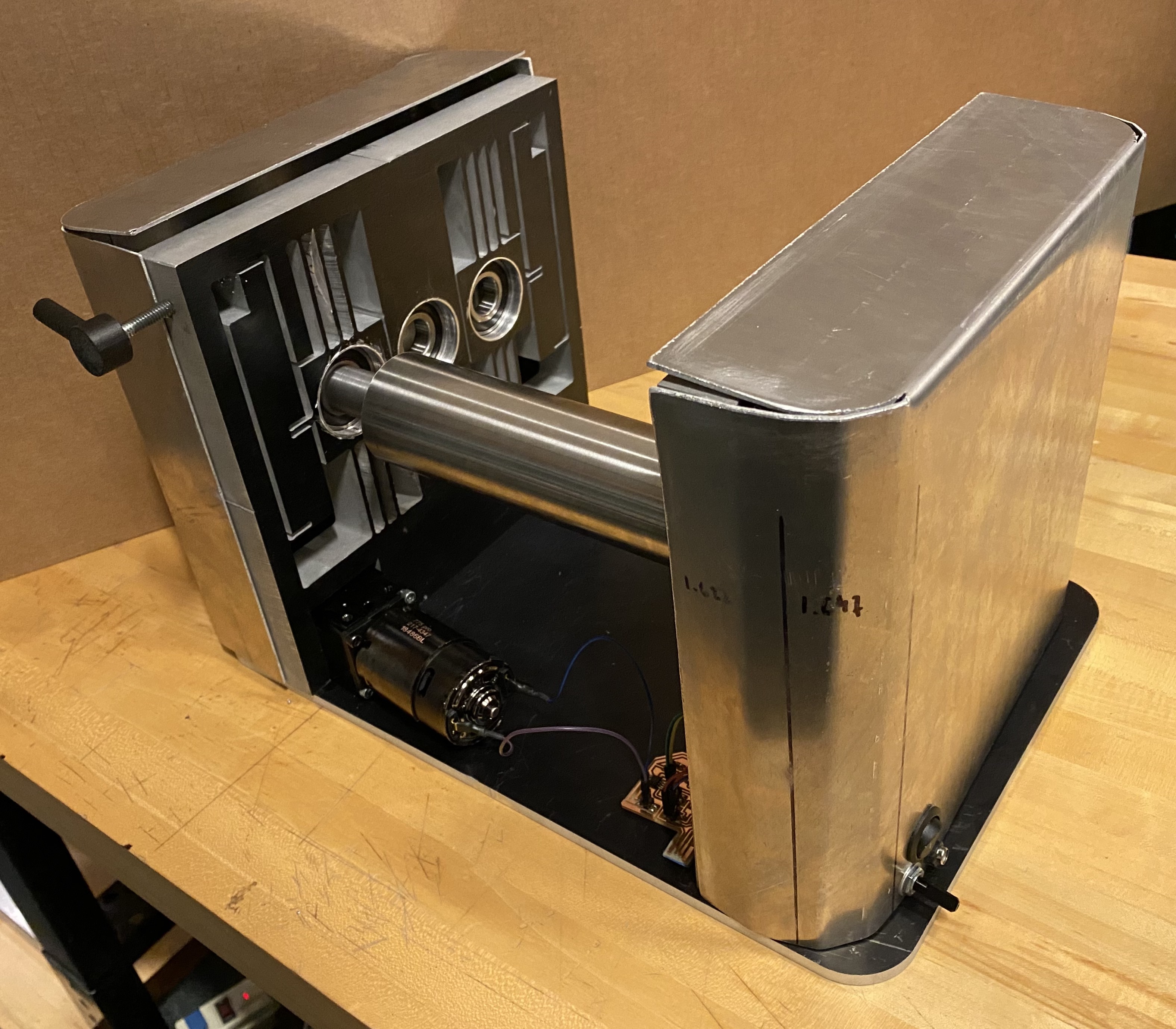
Mill with covers and electronics.
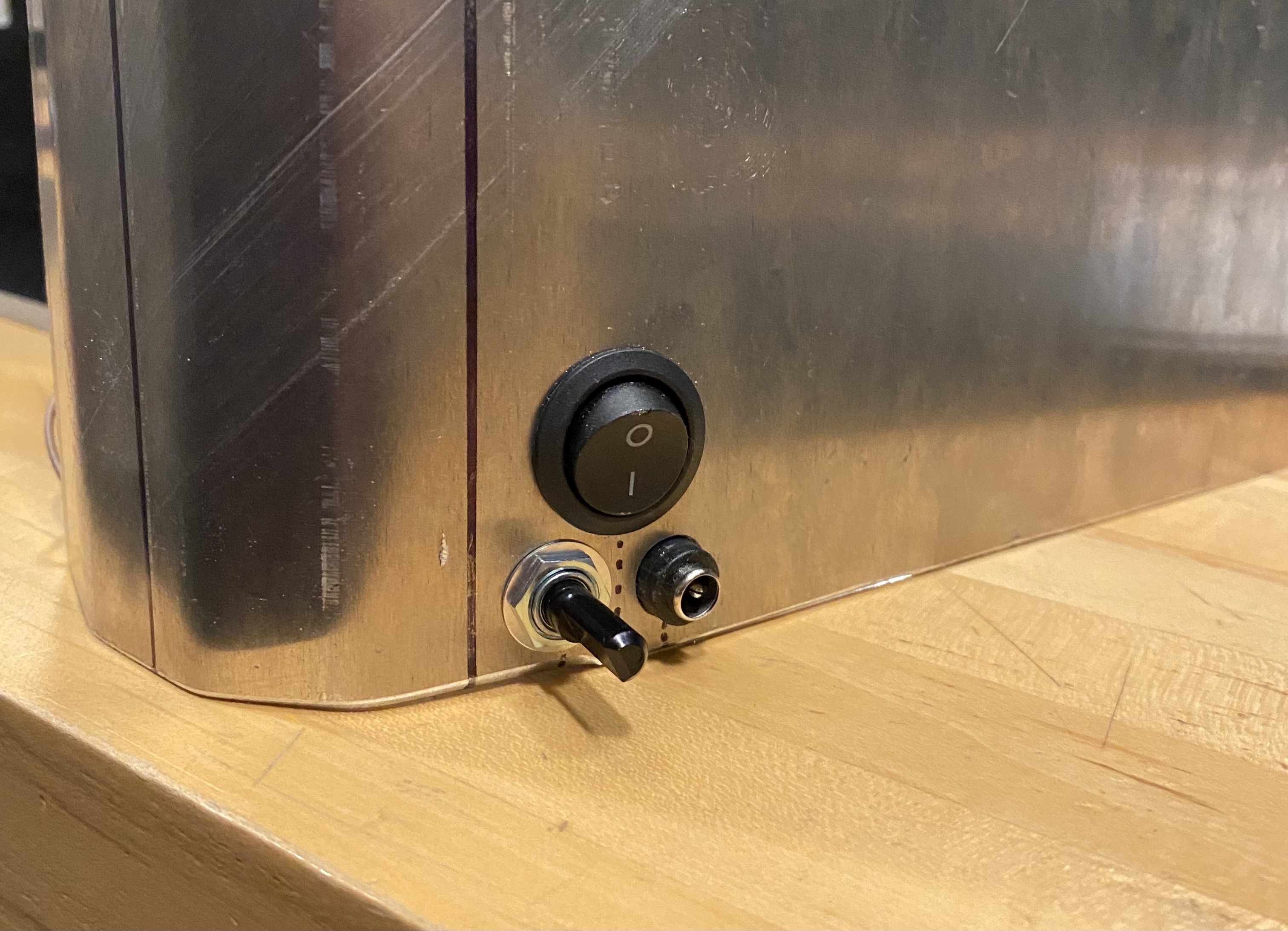
Here's how the potentiometer, power jack, and switch sit in the cover.
Wrapup
And that's my mill! Here's an overview of the project:
What does it do?: my mill's intended purpose is to increase the efficiency of my watercolor paint manufacturing process. In particular, it performs the stage in
which I pulverize the pigment particles to ensure the paint is smooth and homogenous. So far, my mill spins one roller, but I am going to add the other two and make some aesthetic
elements for the machine over IAP.
Who's done it beforehand?: In particular, I was looking at Torrey Hill's three roll mills for inspiration and guidance.
What did I design?: The flex plates, inner plates, baseplate, covers, electronics, rings, shafts & rollers, plus the not-yet-implemented guides and paint scoop.
Materials and components:
Gears: McMaster, $153.86
3 ft of stainless steel tubing: McMaster, $73.91
755 Pro Motor: VEX Robotics, $19.99
VersaPlanetary Gear Box: VEX Robotics, $100
Electronics: from the EE and Architecture shops
Aluminum plate: from the LMP shop
Steel tubing: from the LMP shop
3D printed handles: fabricated on the Mediated Matter's Markforged printer
I learned so, so much by working on this project and am so excited to keep refining it! I'm really proud of how it turned out and can't believe that it's actually going to make paint. Because I've never made a machine before, and because market 3 roll mills look so professional, I somewhat doubted my ability to actually make one; I feel really empowered now, especially since I learned so much machining over the past few weeks. I feel like a real MechE and can't wait to tackle more challenges in the future.