Designing
It's input devices week, so my goal is to learn how to make a PCB with a potentiometer, which will come
in handy for my final project. I'll be using a motor to spin the rollers of my 3 roll mill, so I'd like to use a potentiometer
to adjust the spin speed -- this will take a form of a little dial on the control panel.
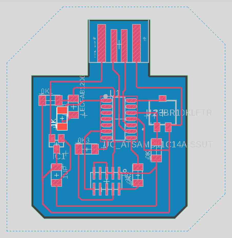
Here are my initial designs in Eagle for a D11C PCB:
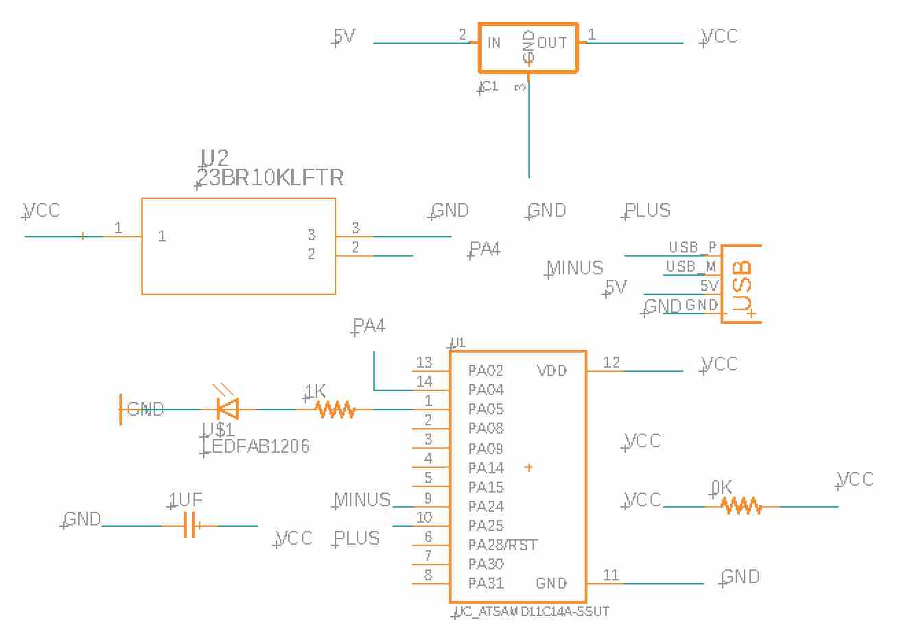
I had to design my PCB from scratch, since I transitioned from using an ATTINY to a D11C. I worked with an ATTINY last electronics week to keep my board simple, but it wasn't very efficient to hook up to a computer for coding since I needed a lot of adapter wires; I'll no longer have that problem with a D11C thanks to the USB connection.
Fabricating
I excluded the 5x2 pin header from my design, thinking that I didn't need it for the board. Thinking I only needed a USB connection, I completely forgot that it's required
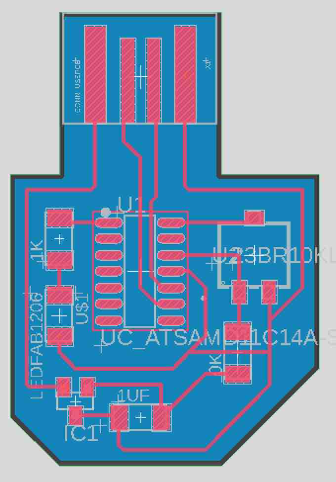
for bootloading the D11C! I only realized this after milling and soldering when I chatted with Laura at her office hours. Here are my new designs:
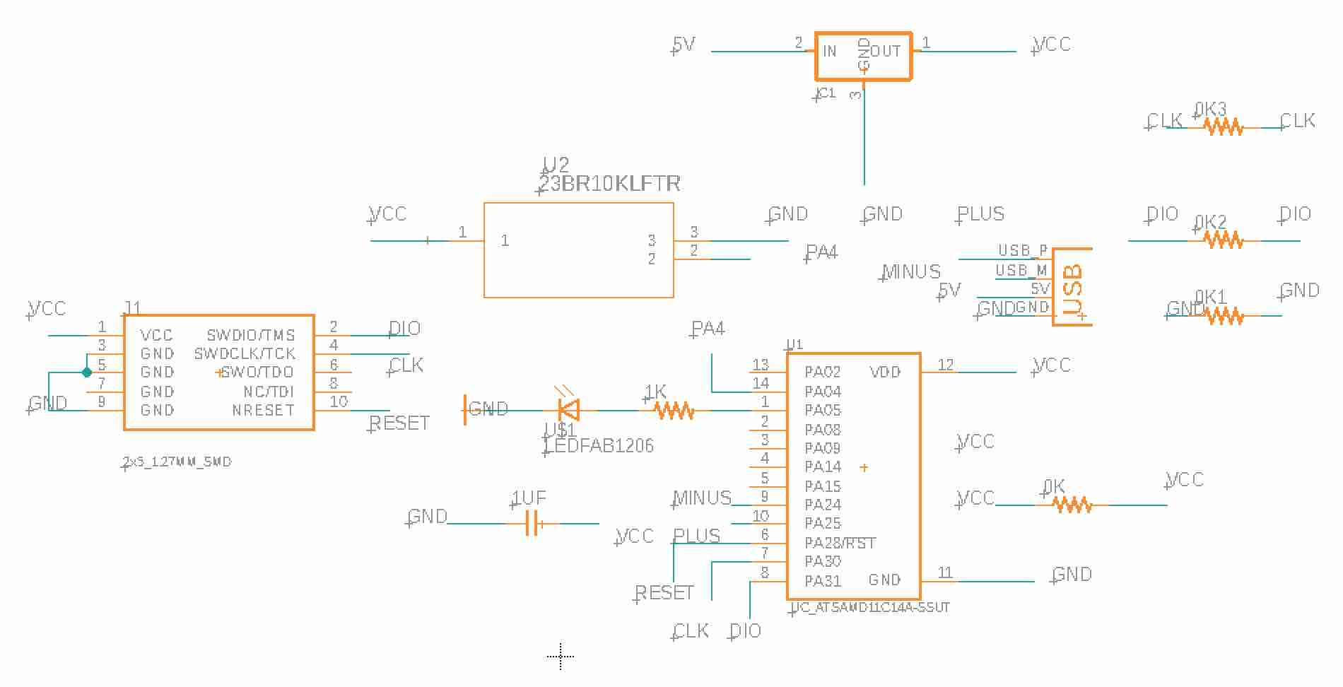
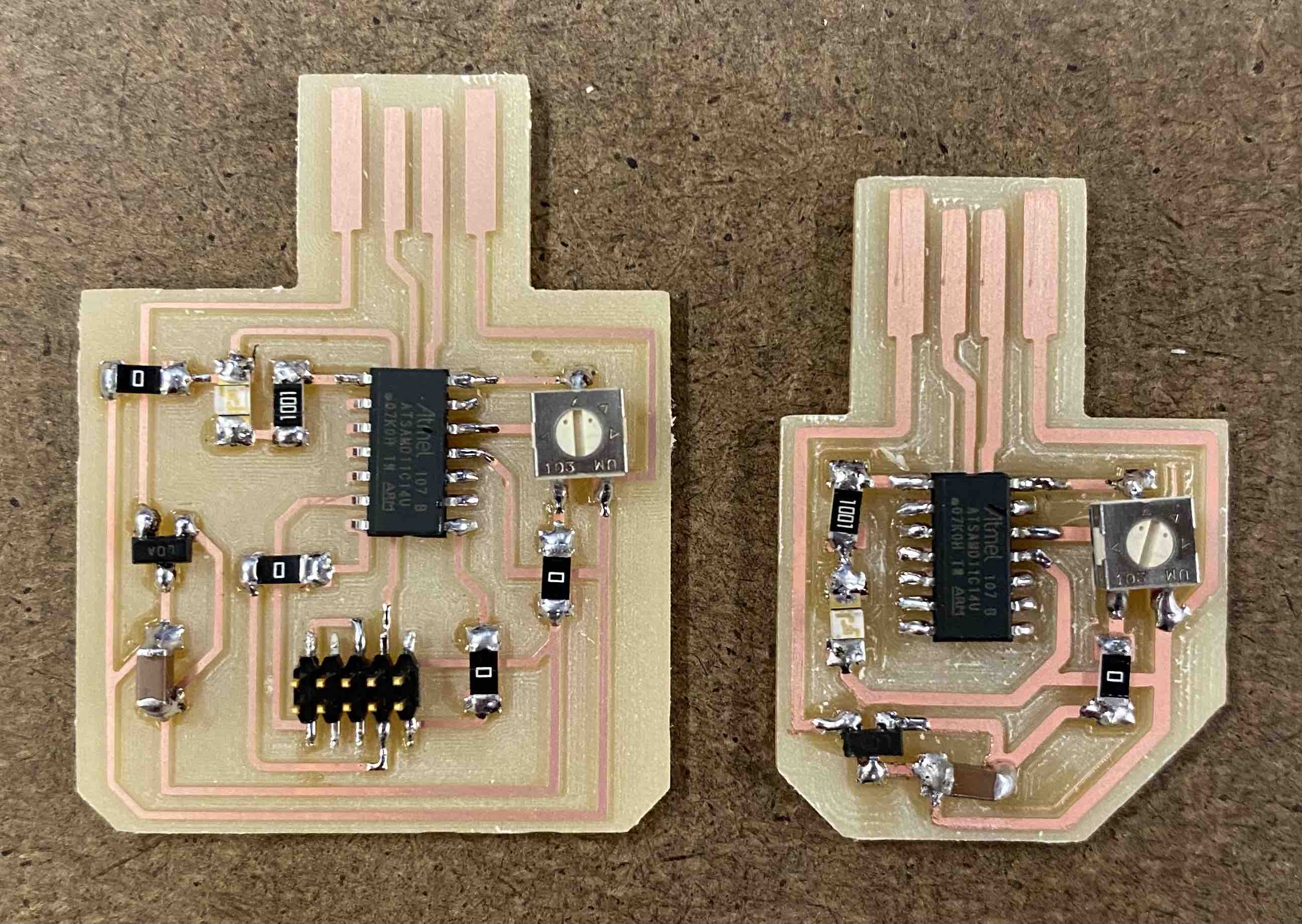
In the process of routing the header to the D11C microcontroller, I had to add several 0 ohm resistors to make everything connect. If I had more time, I would've tried to find a more efficient way of routing everything so I needed less resistors.
Coding
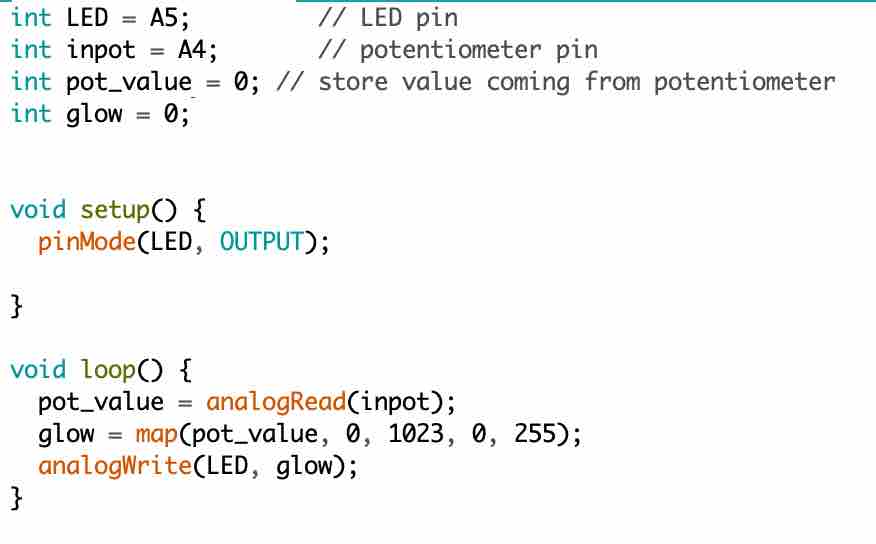
Next, I opened up the Arduino IDE and wrote some code. I wasn't sure how to make the LED glow brighter/dimmer depending on the potentiometer
reading, but after a quick Google search, I found some examples. The map command converts one number range to the next -- I had to use this
since Arduino's analogRead value range is different from its analogWrite range. This seems pretty inefficient, so I wonder why it is this way.
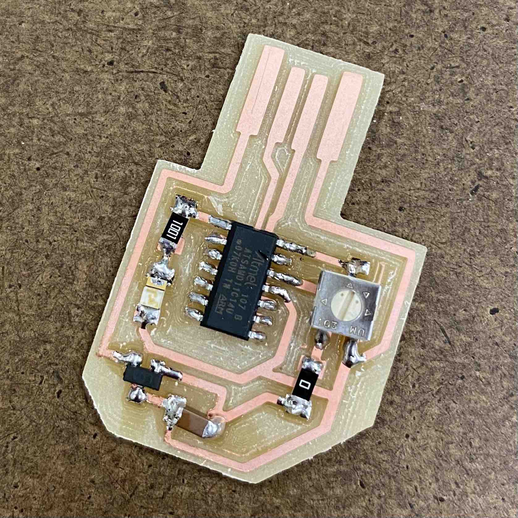
And here's the board in action! I wound up finding a tiny screwdriver in a forgotten emergency glasses repair kit in my backpack, which was perfect for
adjusting the potentiometer.