Designing
For networking week, I'll be making two PCBs that talk to each other; the potentiometer on A controls the LED on B and vice versa.
I'll be using my PCB design from Week 9, but modifying it.
Here are my designs in Eagle:
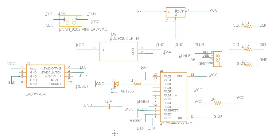
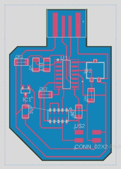
To adapt my Week 9 design for networking, I added a 2x2 header with pins for Tx, Rx, VCC, and GND; this will be how I connect the two boards.
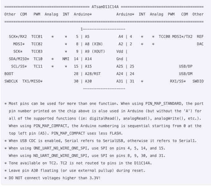
This mapping guide from the CBA documentation was really helpful for figuring out which pins on the D11C correspond to Tx and Rx.
Fabricating
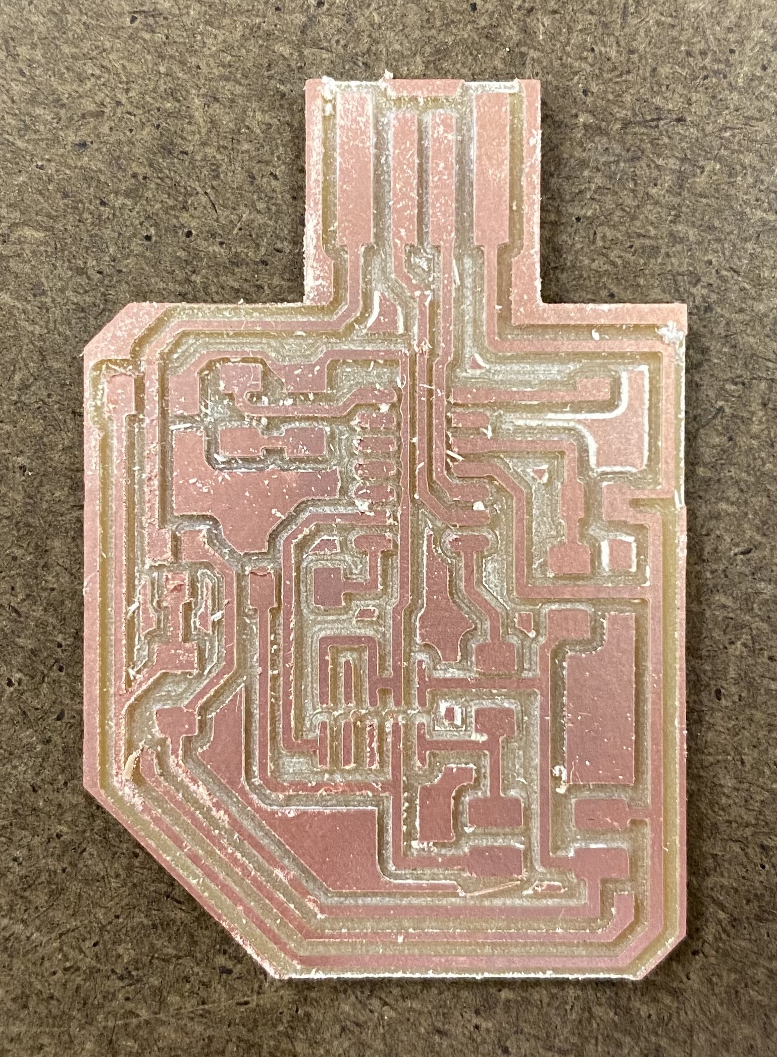
I usually mill with an offset of 0 and tried out offset 2 last week to disatisfaction, so this week, I tried offset 4. And then I finally realized what
offset was doing, since I had a vague grasp of the concept. It helped that this time I actually looked at the toolpath for this board; there were 4 paths bordering the traces, 4 offsets. Decreasing from 4 results in less
of an offset -- I had got this all wrong, thinking that 4 was not offset much since 0 cleared the whole board. I wish I had realized this earlier, since milling all my boards at offset 0 has taken
hours, when offset 4 was pretty decent while being relatively quick this whole time.
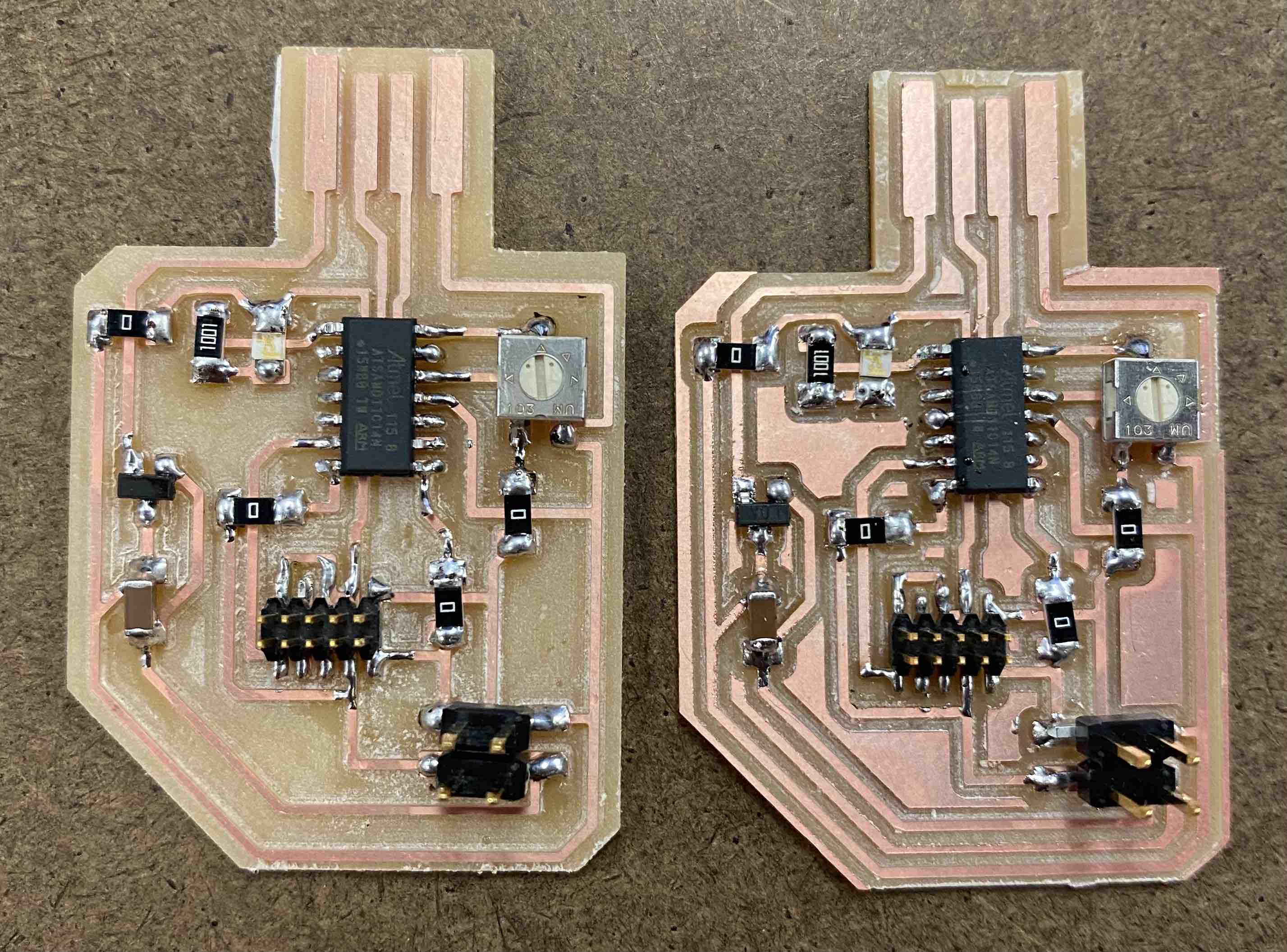
Before trying offset 4, I had used offset 0 on my first of the boards, hence they're both different. It's fun to compare.
Coding
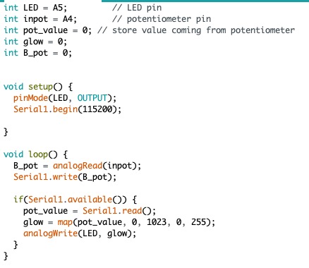
Next, I opened up the Arduino IDE and adapted my code from Week 9, adding in Seriai commands to incorporate networking. This is my original code before I started troubleshooting.
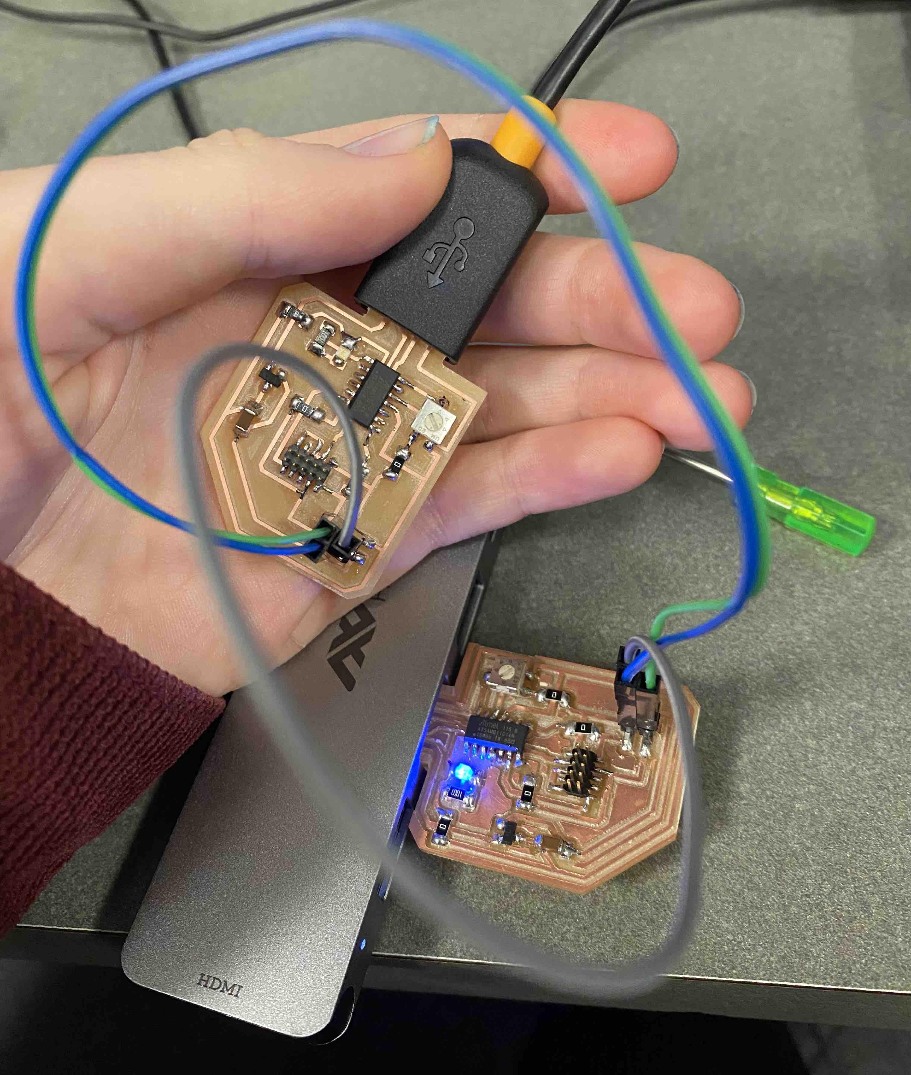
With Anthony's help, I was able to get the light on one board to glow based on the position of the potentiometer on the other board. It was a little finicky, not smoothly increasing and decreasing in brightness, so we took a closer look at my code...
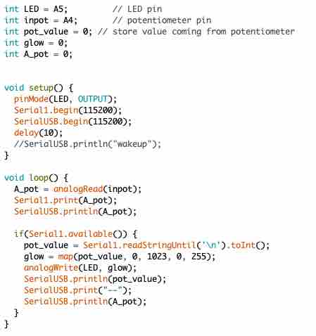
At the end of several hours, here's what Anthony and I had written to try and make the boards run as intended. We used a lot of print commands so we could check if the potentiometers were actually being read, which let us view the inputs in the serial monitor. The boards started acting up, not being recognized by my adapter cable ports, requiring bootloading again, and even requiring the Atmel ICE to be programmed. We decided to call it a night and review this in the future. I didn't have much time left, and it didn't help that my computer's screen broke.