Designing
It's output devices week, so my goal is to learn how to make a PCB with a brushed DC motor. This will come in handy for my final project.
I'll be using a motor to spin the rollers of my 3 roll mill, and the user can turn a little dial on the control panel to adjust the speed. This week, I'll simplify this
task by using a potentiometer to control the speed of a small DC motor.
Here are my initial designs in Eagle for a D11C PCB:
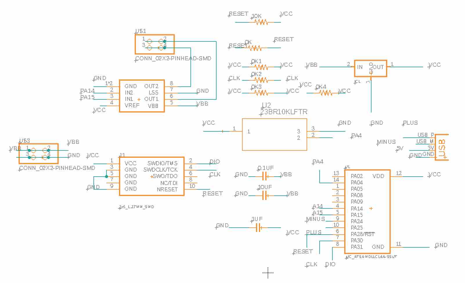
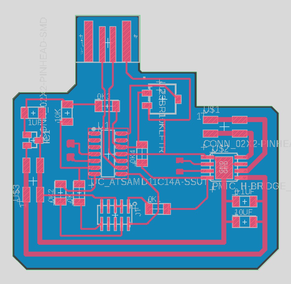
I somewhat adapted my PCB from last week; I initially hoped I could just adjust the routing a bit, but I wound up routing everything from scratch so I could better understand how all components fit together. I made sure to read the datasheets for the A4950 H-bridge and 232047 Jameco DC motor so I wouldn't supply them too many volts.
Fabricating
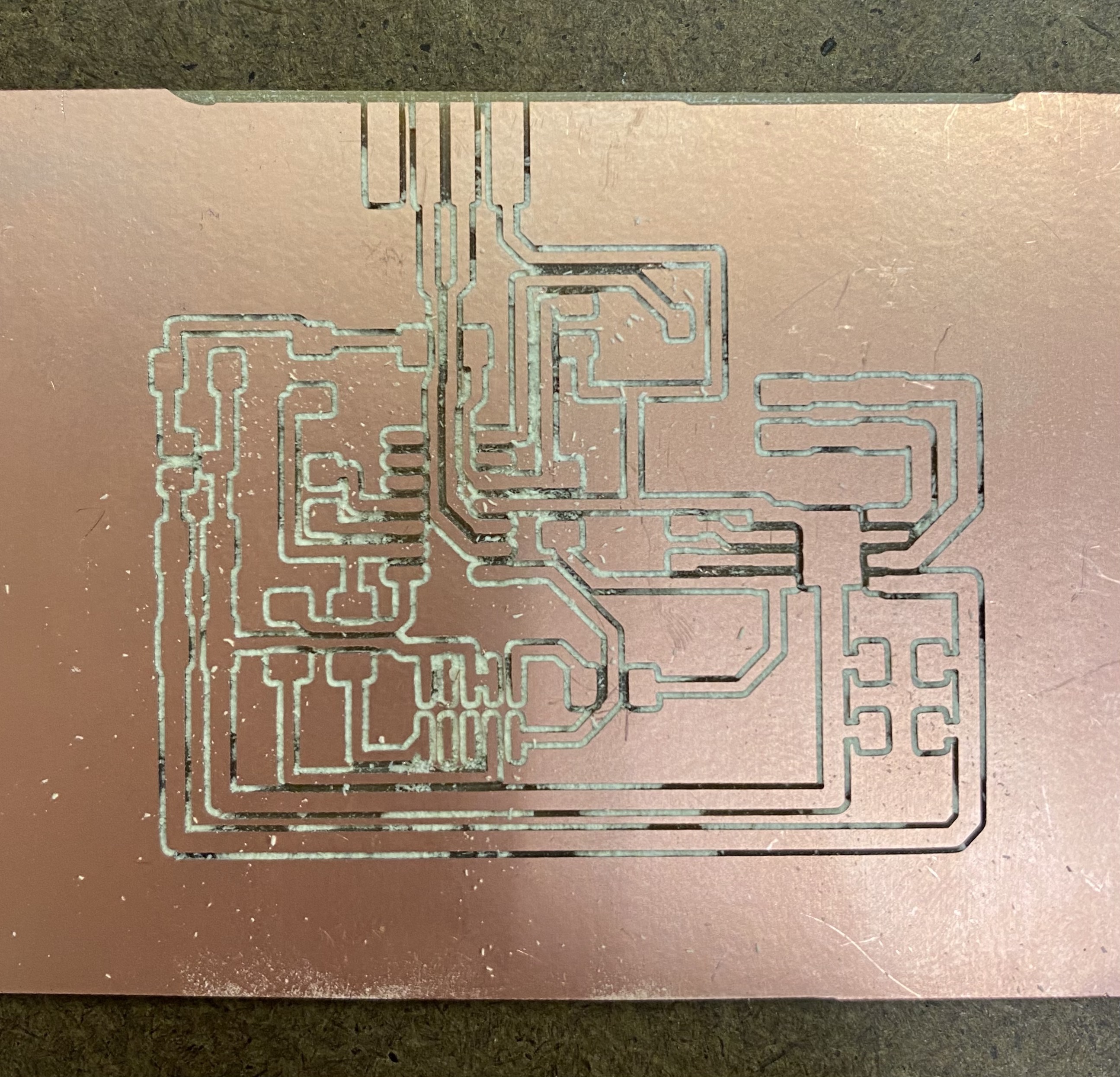
I usually mill with an offset of 0, but this time I tried 2 just to see. In the end, the faster mill speed didn't make up for the quality of the board. I wasn't confident I could solder precisely with the close spacing of the traces.
Also, the USB connector seemed to be cut-off by the edge of the stock, and I didn't want to let it slide and risk not being able to program
the board.
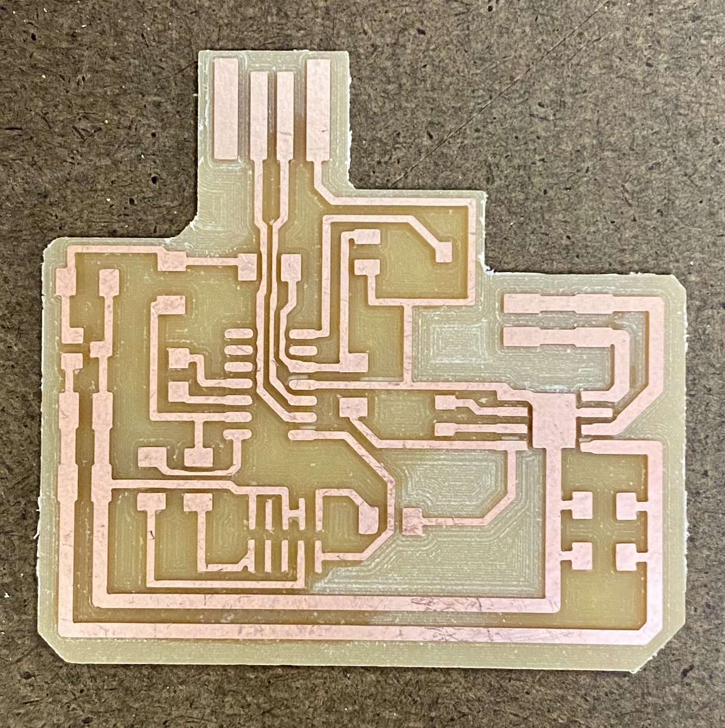
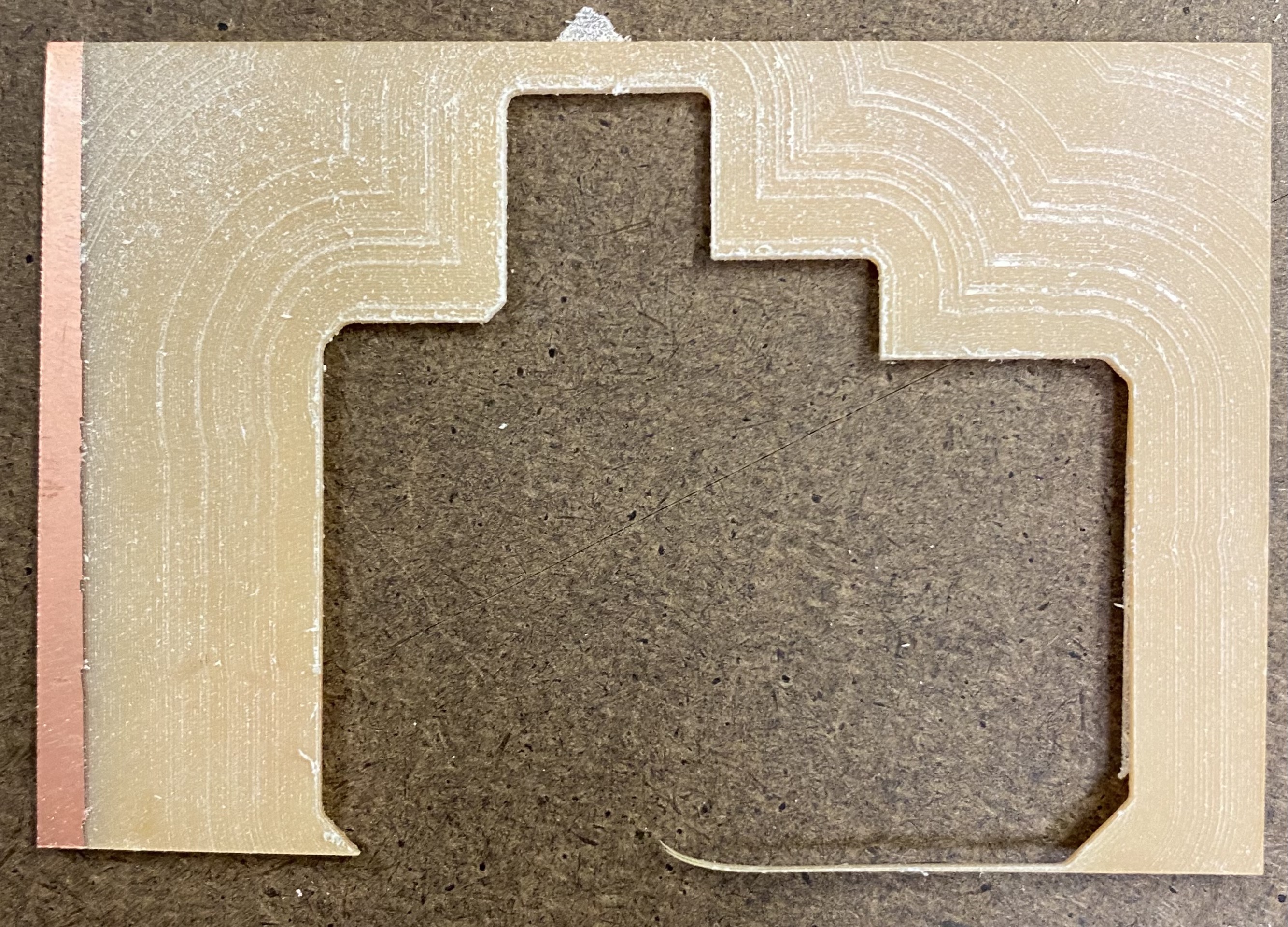
I milled the PCB again, this time with offset 0. It took over 1.5 hours just for the traces, the longest milling has ever taken me. This was because the images I exported from Eagle had a lot of blank space, and the mill had to cut all of that. I didn't realize at first that the png size depends on how big the bottom layer polyon is. I thought I could arbitrarily draw the bounds around the board, but I should have kept it close to the traces to reduce the size of the pngs.
Soldering
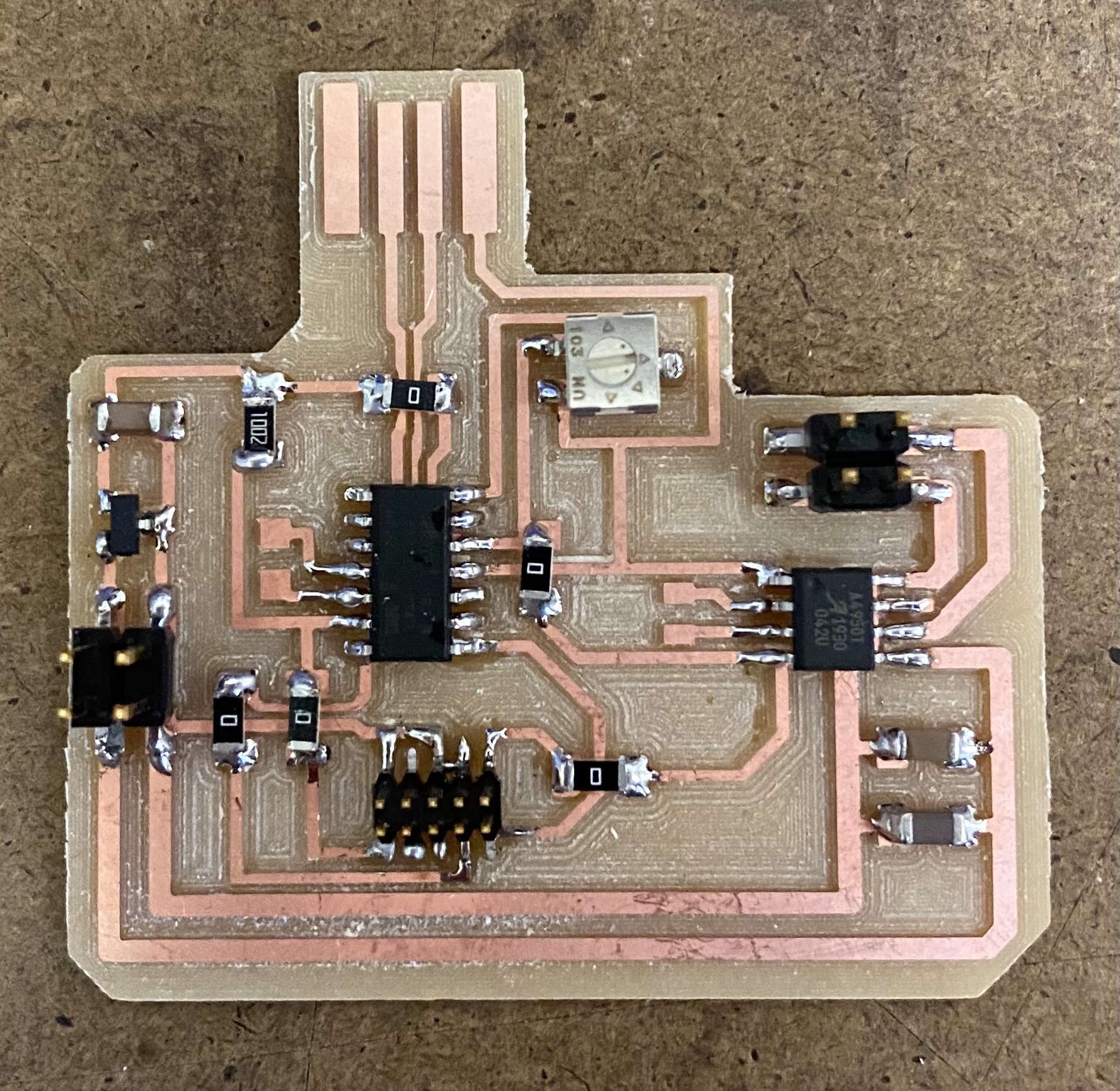
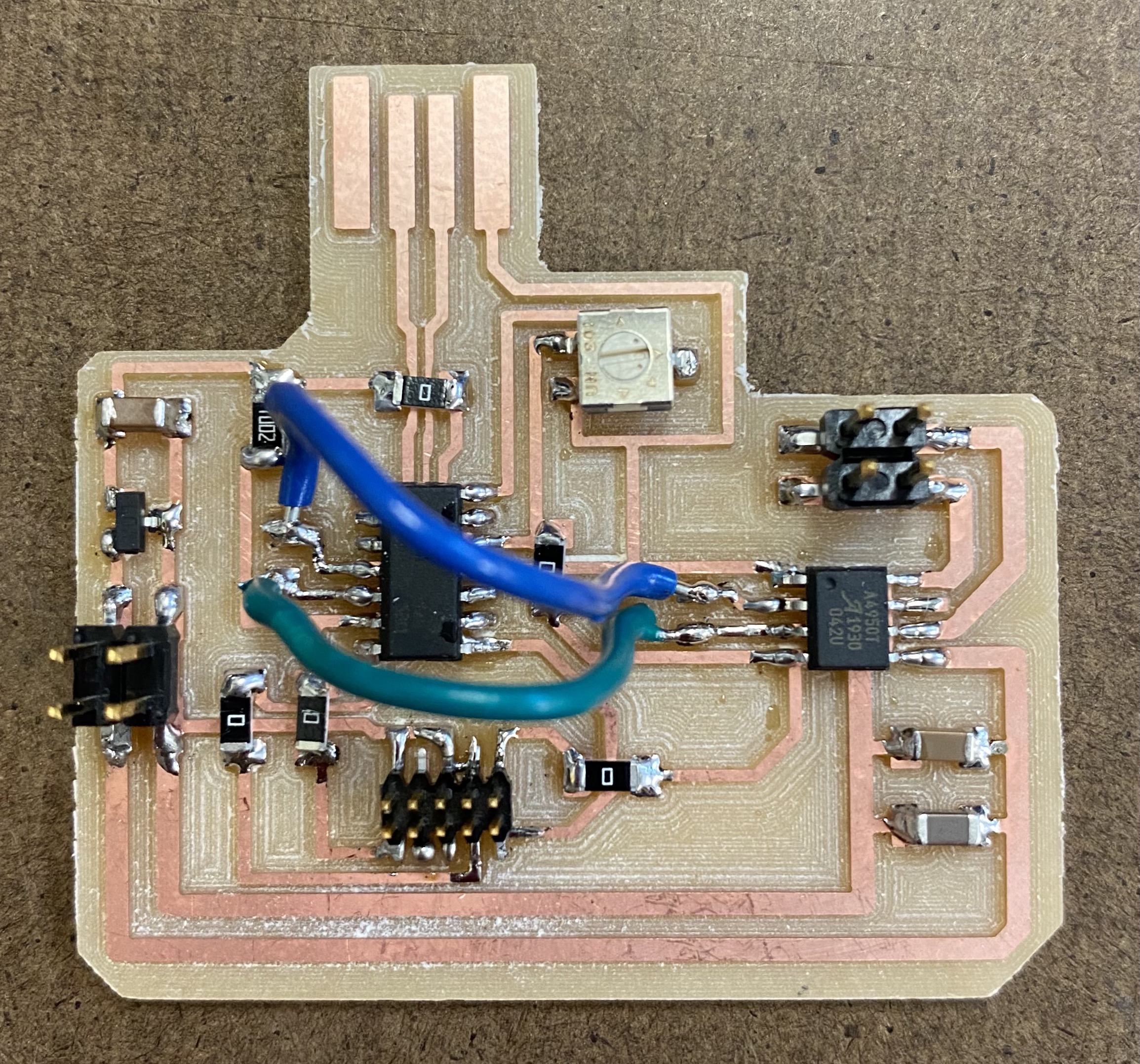
Next, I soldered my board -- I connected the H-bridge to the D11C pins through wires since it would have been tricky to rout in Eagle.
Coding

To provide power to the motor, I'm using a 12 volt supply that connects to my board's 2x2 header. To connect the motor, I soldered two wires to its feet, then connected the wires to the other 2x2 header.
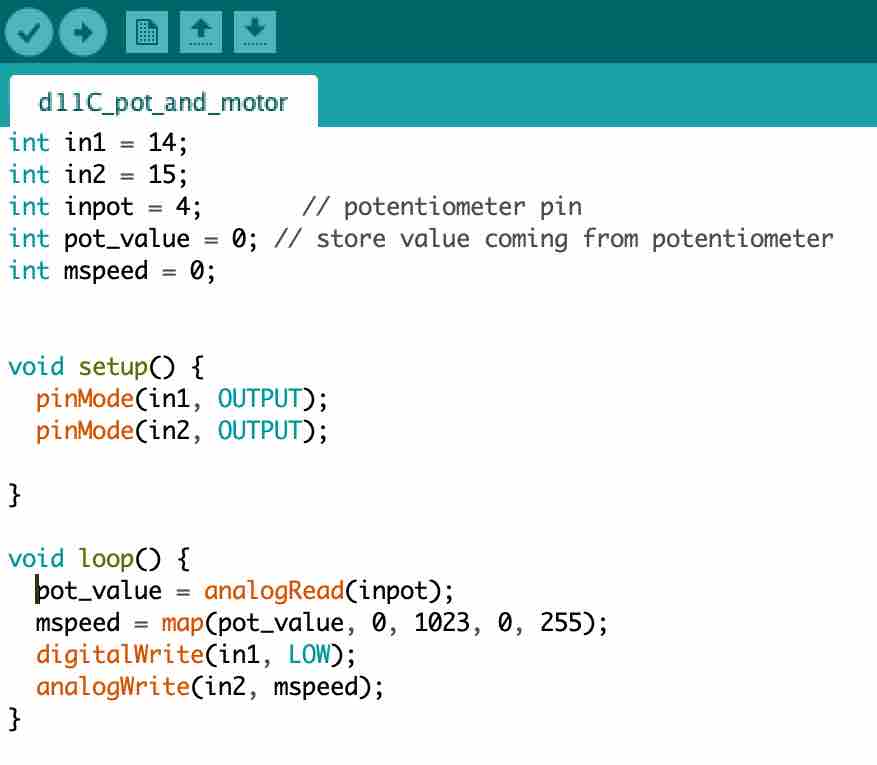
Here's the code I wrote in the Arduino IDE. in1 and in2 are the D11C pins that the H-bridge connects to. Similar to my code
for the potentiometer-controlled-LED from last week, I map from the potentiometer values to the values the output can read. The motor
turns when one input is LOW and the other is HIGH, and here I have the HIGH pin be at a specific speed (hence analog rather than digital) determined by the position of the potentiometer.
The motor is super fast! I should've realized this when looking at the Jameco product specs and it said 19,850 RPM. When I didn't have
the speed control in the code and only programmed it so that the motor turned on, as soon as I connected power, the motor went crazy; it spun super fast and screamed like a drill. This was because it was automatically at 12V, the potentiometer not reducing it.
But anyway, the code and PCB wound up working as intended, so I look forward to implementing what I've learned in my final project.