Electronics Production
PCB Machining, Components, and Assembly
01 Group Assignment
//
Characterize the design rules for PCB production process
Before we started milling the PCB, we used the file that Neil provided to test the behavior of cuts in different width. The two avalible size of drills are 1/64" and 1/32". We used the 1/64" drill to mill the test piece.
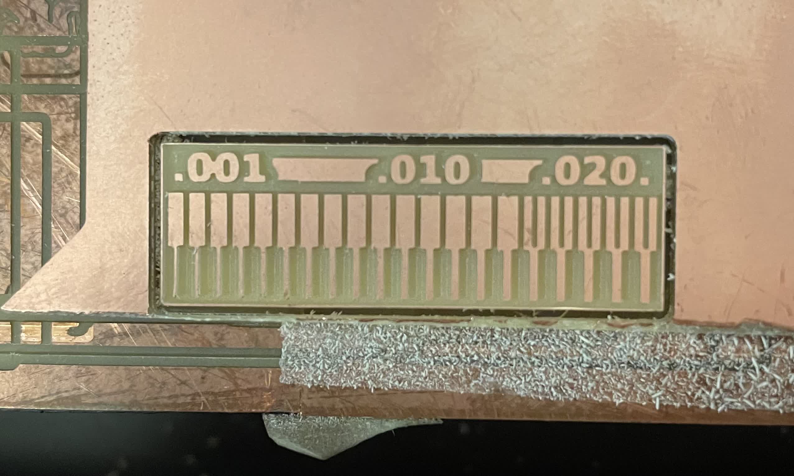
The 1/64" we used drills the board perfectly, but the 1/32" won't do that good because it is too thick for some of the slits.
02 Individual Assignment
//
Mill a in-circuit programmer
I decided to mill a serial adapter for AVRs using the D11C micro controller. I downloaded the interior and the boundry image from the website.
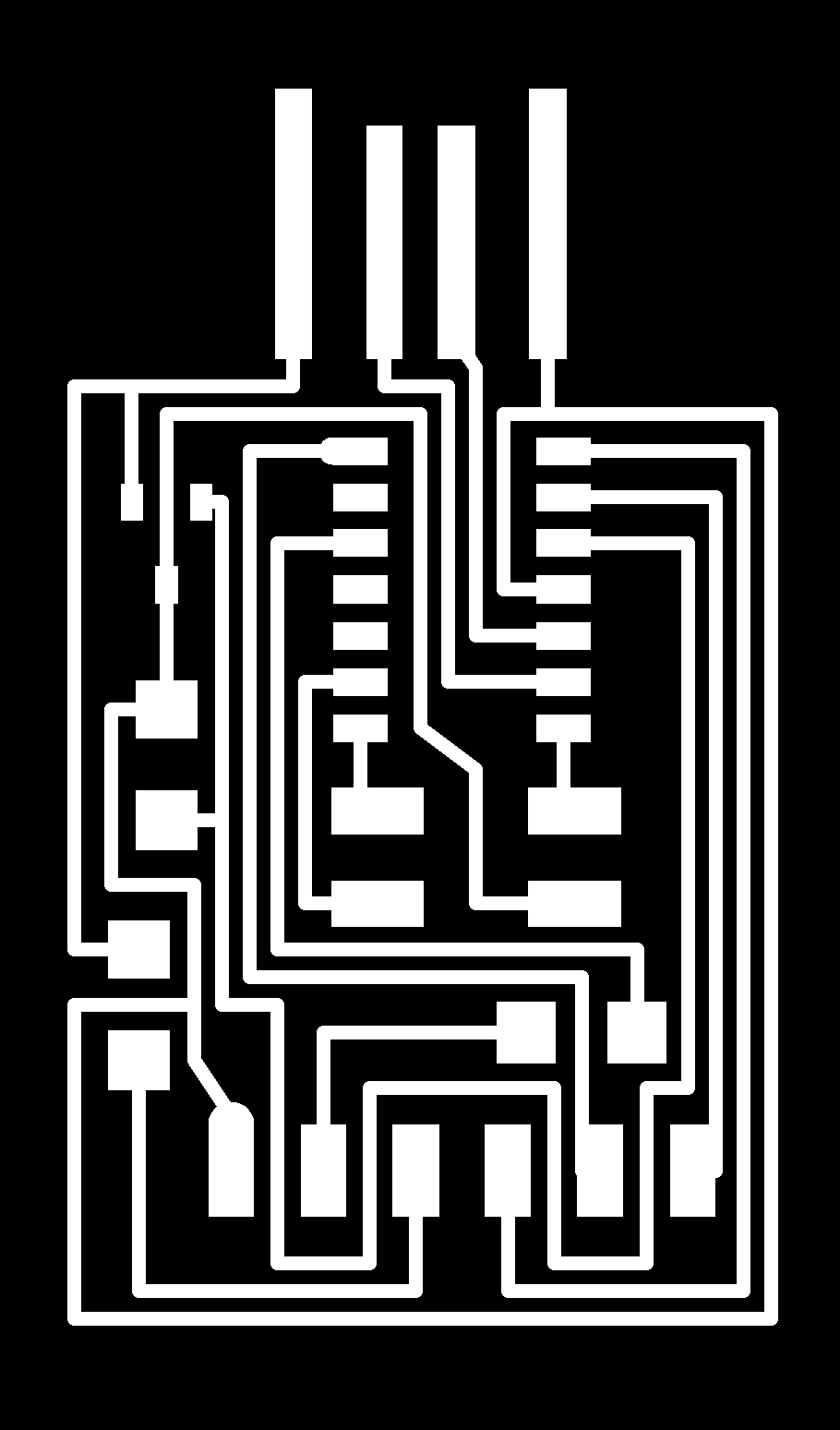

The milling boundries in png format.
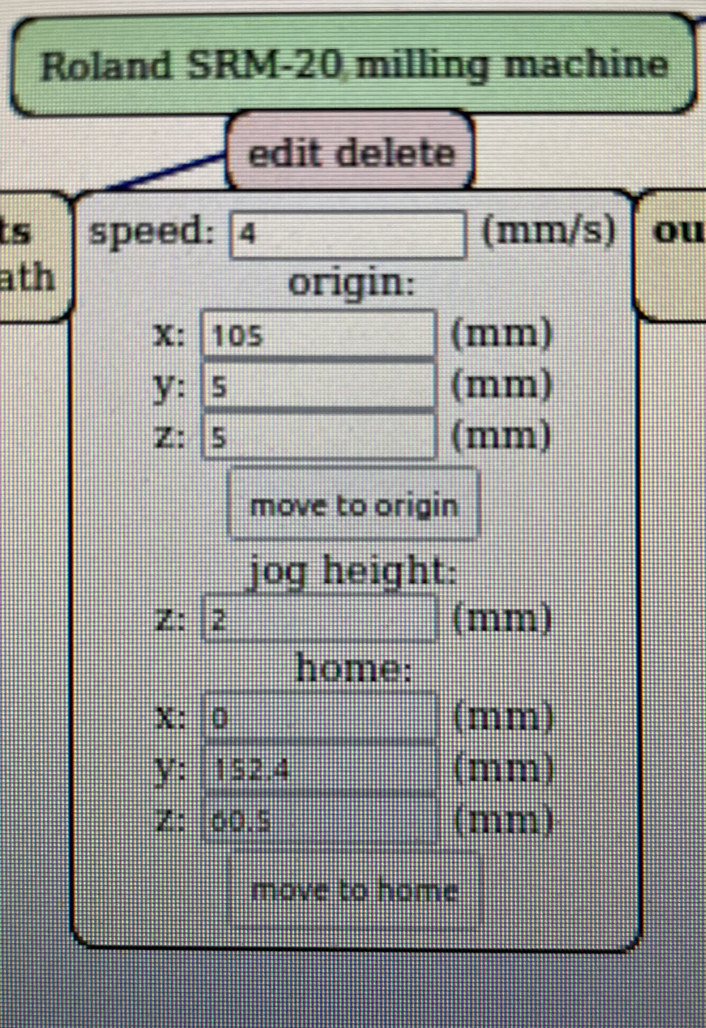
I then uploaded the png image into the mod, found the origin and milled the peice.
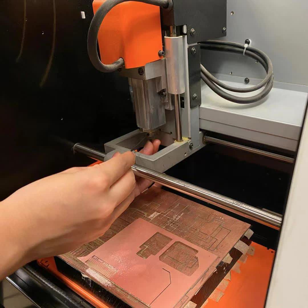
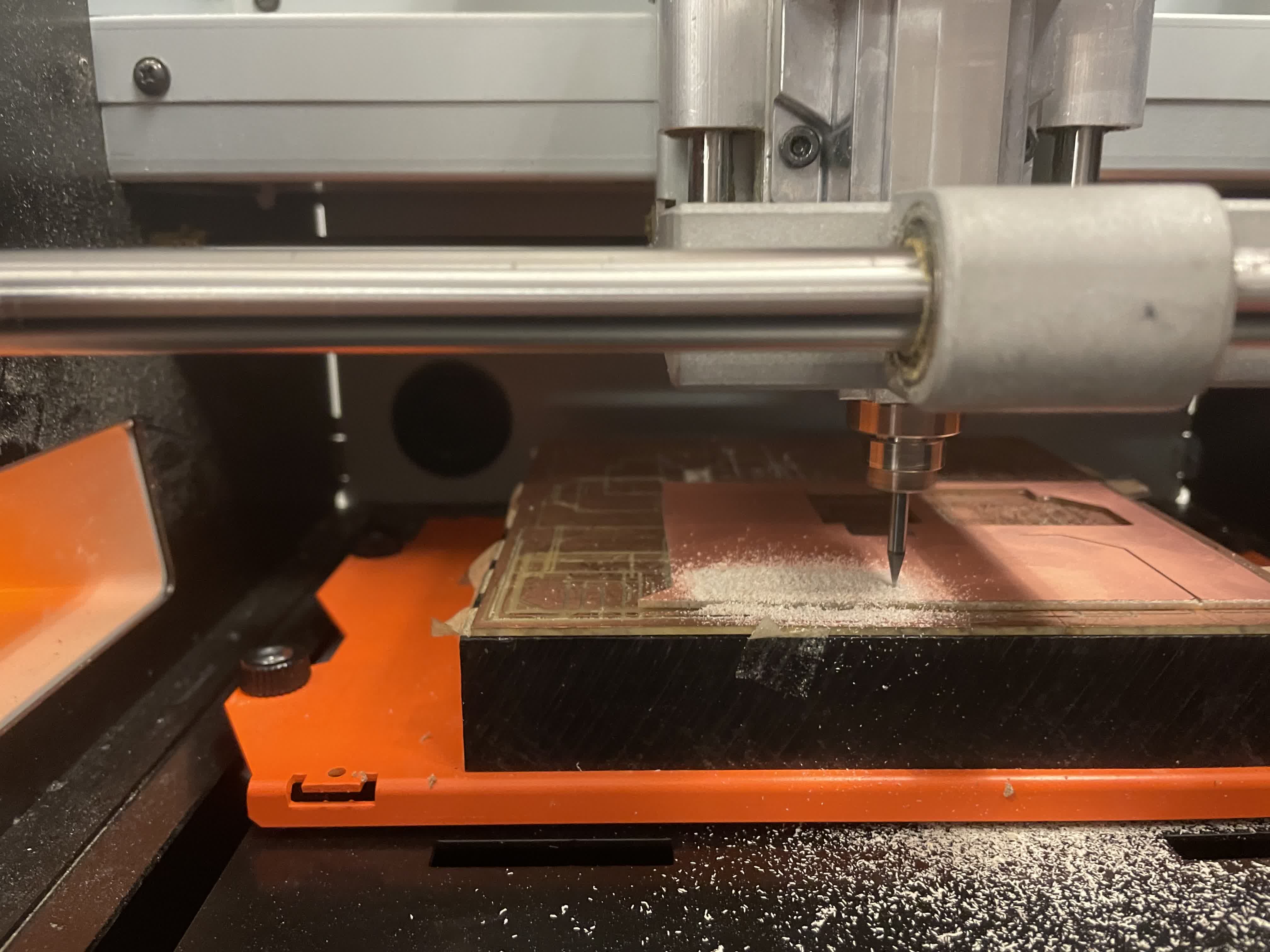
However, the first trial wasn't well because the drill bit was not tightly screwed and the board was moving. I had to adjust the everything and do it all over again!
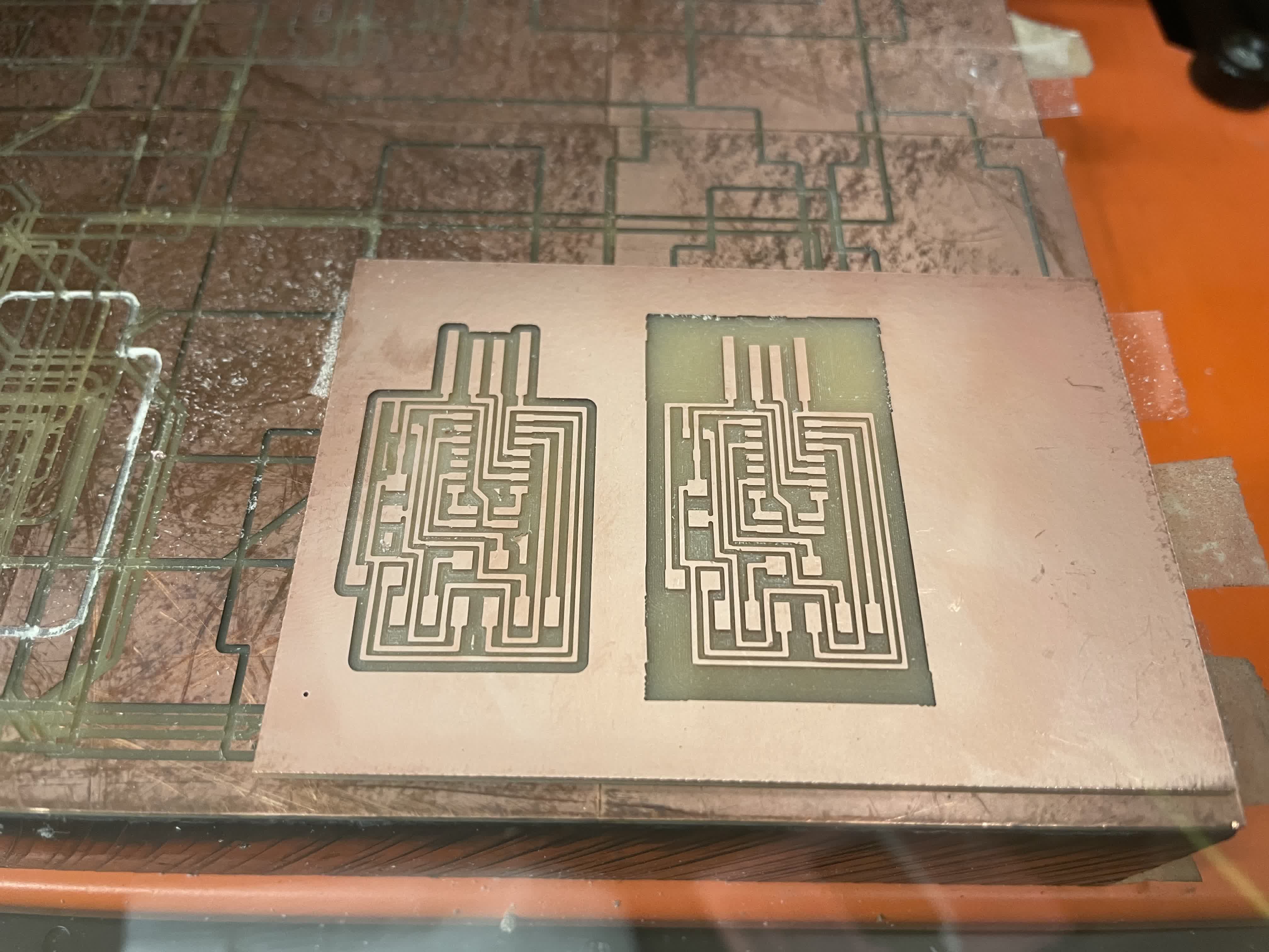
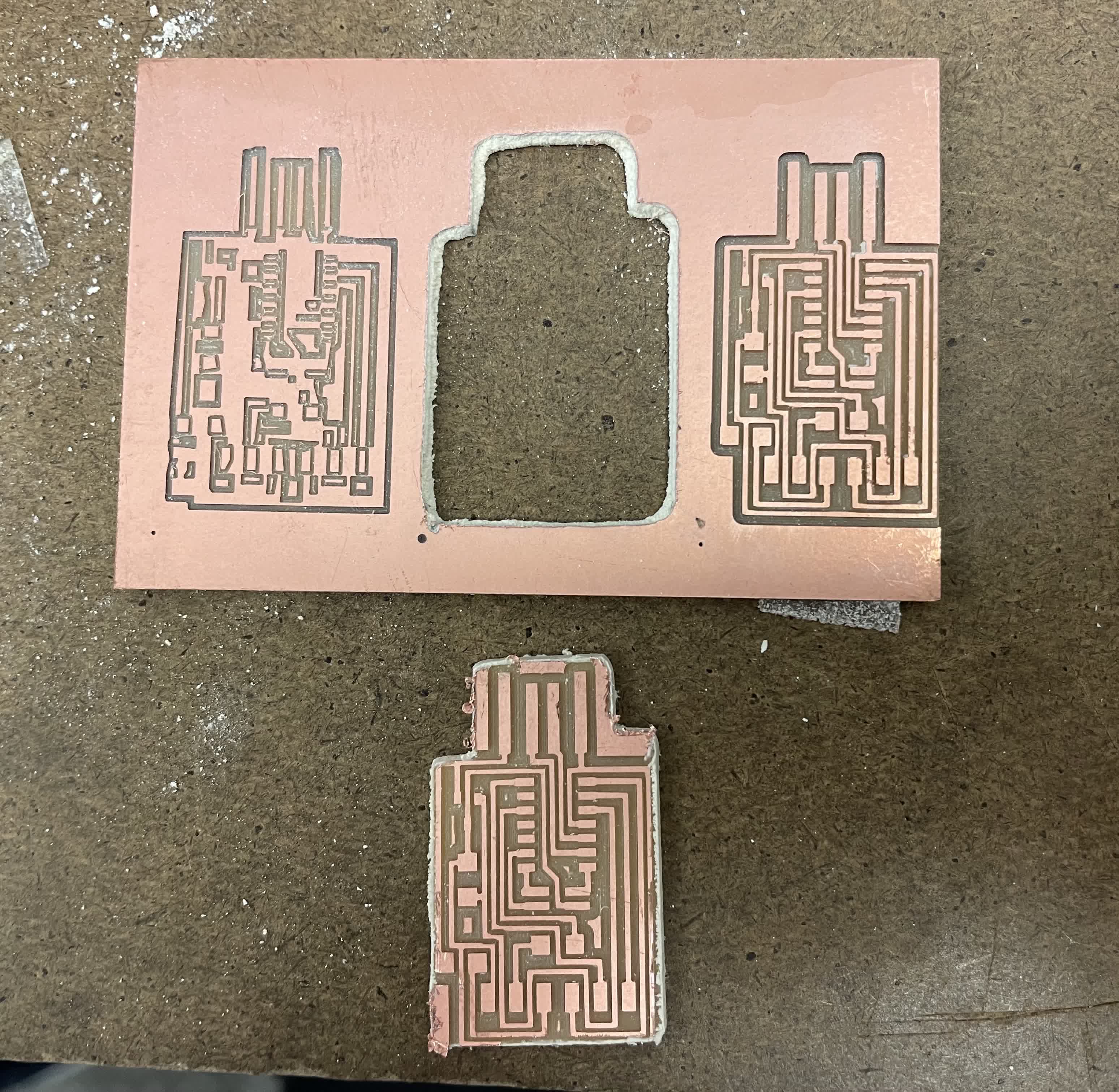
After learning how to adjust properly, we milled the PCB successfully with different settings. The left one has offset set to 4, and the right one has the offset set to 0.
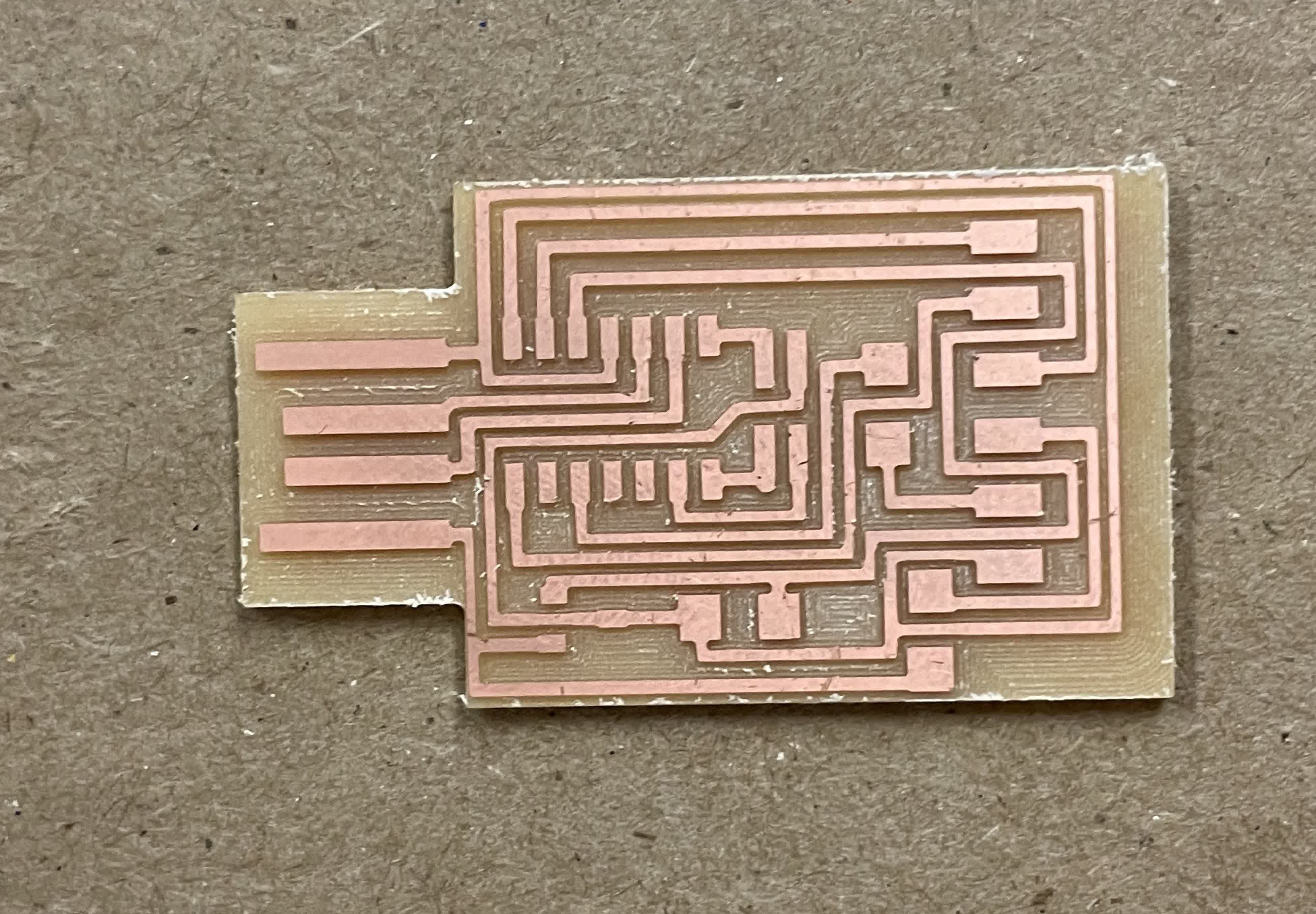
I then used the outlien image to mill through the board. The result looks very decent and clean!
//
Soldering the PCB
The next step is to take the finished board and stuff it with small components like microcontrollers and resistors. I followed the image from the course website and found all the corresponding components in the drawers.
.png)
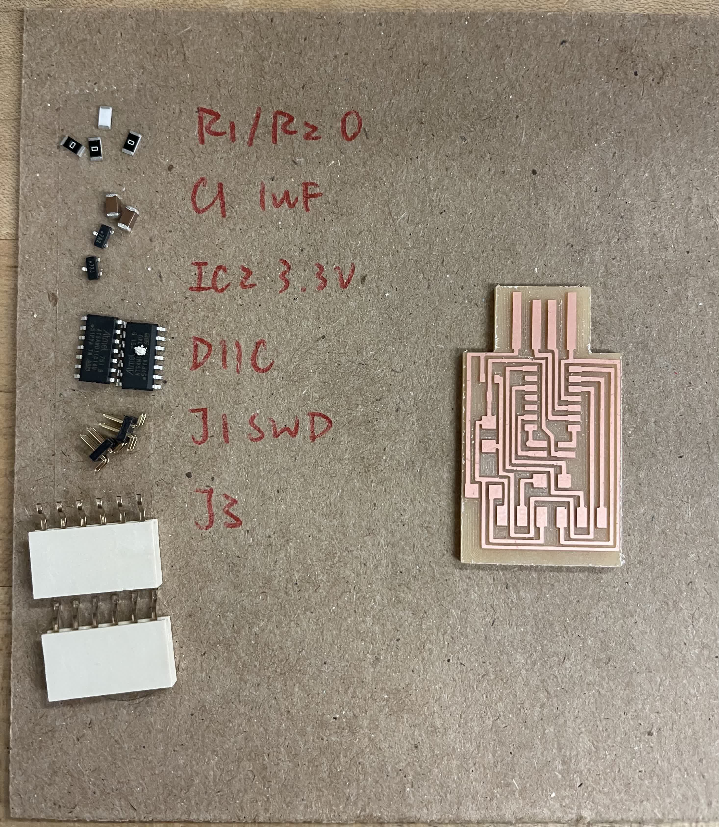
The left image indicates all the needed components. I glued them onto a cardboard and started soldering. I had to see use the magnifying glass in order to see everything clearly.
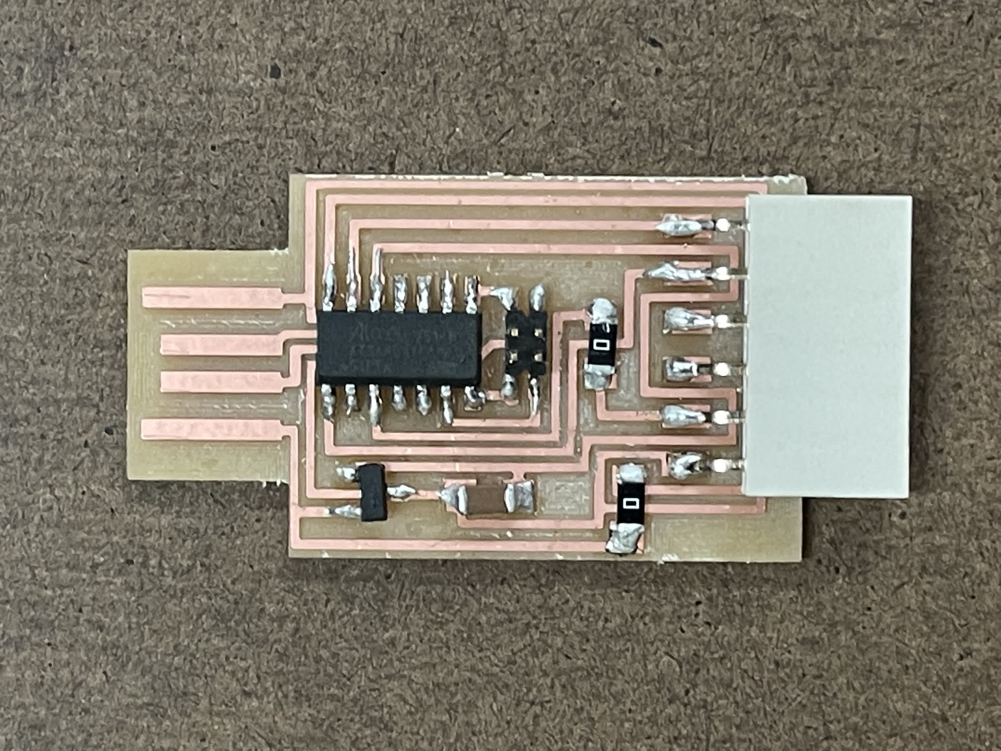
Here is the finalized PCB! I took a few practices of solding on a broken PCB board so the actual solding on the finalized board went well. Now is the time to test whether it works or not!
//
Test the PCB
I used a multimeter to test whether there are current flowing through all the components. I used the tips to touch two connecting components and check if the multimeter will make a "beep" sound. If it does, that means the solder for that part is good.
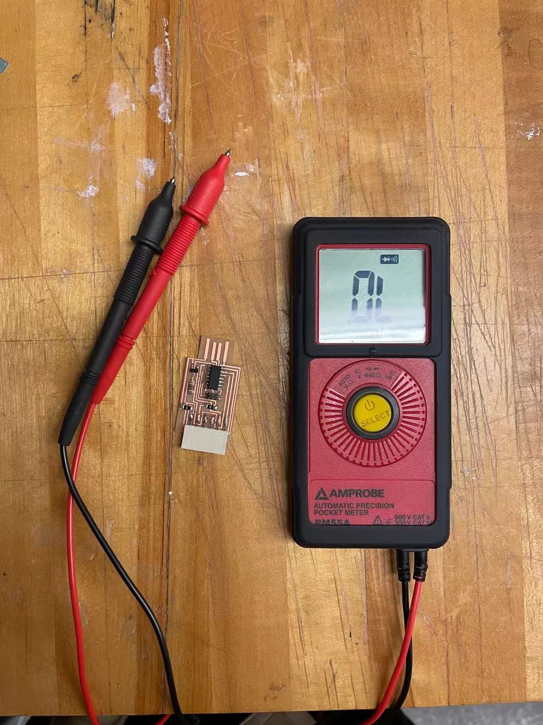
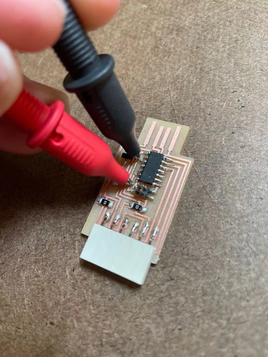
I tested most of the joints and they all seem to be working. However, it is very hard to find some of the connecting points on the board because the lines are partially covered by the components. We also tried to plug it into the computer and see whether it is going to show up as a disk. Unfortunately it didn't show up, but I will check back again during the programming week.
03 Conclusion of the Week
//
Gained skills
Roland milling machining and solding
Thoughts and lessons learned
I summarized a few mistakes I did for this week. First, I didn't wash my PCB board before it's soldered, so the solder's flow is not very well on the board, that increased the risk of messing up the solder. Second, it is quite important to make sure there are no dust on the surface of the panel before putting on the material. This will cause the unevenness of the drill pass.